
2.1: Starting a Sketch
- Page ID
- 31523
\( \newcommand{\vecs}[1]{\overset { \scriptstyle \rightharpoonup} {\mathbf{#1}} } \)
\( \newcommand{\vecd}[1]{\overset{-\!-\!\rightharpoonup}{\vphantom{a}\smash {#1}}} \)
\( \newcommand{\id}{\mathrm{id}}\) \( \newcommand{\Span}{\mathrm{span}}\)
( \newcommand{\kernel}{\mathrm{null}\,}\) \( \newcommand{\range}{\mathrm{range}\,}\)
\( \newcommand{\RealPart}{\mathrm{Re}}\) \( \newcommand{\ImaginaryPart}{\mathrm{Im}}\)
\( \newcommand{\Argument}{\mathrm{Arg}}\) \( \newcommand{\norm}[1]{\| #1 \|}\)
\( \newcommand{\inner}[2]{\langle #1, #2 \rangle}\)
\( \newcommand{\Span}{\mathrm{span}}\)
\( \newcommand{\id}{\mathrm{id}}\)
\( \newcommand{\Span}{\mathrm{span}}\)
\( \newcommand{\kernel}{\mathrm{null}\,}\)
\( \newcommand{\range}{\mathrm{range}\,}\)
\( \newcommand{\RealPart}{\mathrm{Re}}\)
\( \newcommand{\ImaginaryPart}{\mathrm{Im}}\)
\( \newcommand{\Argument}{\mathrm{Arg}}\)
\( \newcommand{\norm}[1]{\| #1 \|}\)
\( \newcommand{\inner}[2]{\langle #1, #2 \rangle}\)
\( \newcommand{\Span}{\mathrm{span}}\) \( \newcommand{\AA}{\unicode[.8,0]{x212B}}\)
\( \newcommand{\vectorA}[1]{\vec{#1}} % arrow\)
\( \newcommand{\vectorAt}[1]{\vec{\text{#1}}} % arrow\)
\( \newcommand{\vectorB}[1]{\overset { \scriptstyle \rightharpoonup} {\mathbf{#1}} } \)
\( \newcommand{\vectorC}[1]{\textbf{#1}} \)
\( \newcommand{\vectorD}[1]{\overrightarrow{#1}} \)
\( \newcommand{\vectorDt}[1]{\overrightarrow{\text{#1}}} \)
\( \newcommand{\vectE}[1]{\overset{-\!-\!\rightharpoonup}{\vphantom{a}\smash{\mathbf {#1}}}} \)
\( \newcommand{\vecs}[1]{\overset { \scriptstyle \rightharpoonup} {\mathbf{#1}} } \)
\( \newcommand{\vecd}[1]{\overset{-\!-\!\rightharpoonup}{\vphantom{a}\smash {#1}}} \)
\(\newcommand{\avec}{\mathbf a}\) \(\newcommand{\bvec}{\mathbf b}\) \(\newcommand{\cvec}{\mathbf c}\) \(\newcommand{\dvec}{\mathbf d}\) \(\newcommand{\dtil}{\widetilde{\mathbf d}}\) \(\newcommand{\evec}{\mathbf e}\) \(\newcommand{\fvec}{\mathbf f}\) \(\newcommand{\nvec}{\mathbf n}\) \(\newcommand{\pvec}{\mathbf p}\) \(\newcommand{\qvec}{\mathbf q}\) \(\newcommand{\svec}{\mathbf s}\) \(\newcommand{\tvec}{\mathbf t}\) \(\newcommand{\uvec}{\mathbf u}\) \(\newcommand{\vvec}{\mathbf v}\) \(\newcommand{\wvec}{\mathbf w}\) \(\newcommand{\xvec}{\mathbf x}\) \(\newcommand{\yvec}{\mathbf y}\) \(\newcommand{\zvec}{\mathbf z}\) \(\newcommand{\rvec}{\mathbf r}\) \(\newcommand{\mvec}{\mathbf m}\) \(\newcommand{\zerovec}{\mathbf 0}\) \(\newcommand{\onevec}{\mathbf 1}\) \(\newcommand{\real}{\mathbb R}\) \(\newcommand{\twovec}[2]{\left[\begin{array}{r}#1 \\ #2 \end{array}\right]}\) \(\newcommand{\ctwovec}[2]{\left[\begin{array}{c}#1 \\ #2 \end{array}\right]}\) \(\newcommand{\threevec}[3]{\left[\begin{array}{r}#1 \\ #2 \\ #3 \end{array}\right]}\) \(\newcommand{\cthreevec}[3]{\left[\begin{array}{c}#1 \\ #2 \\ #3 \end{array}\right]}\) \(\newcommand{\fourvec}[4]{\left[\begin{array}{r}#1 \\ #2 \\ #3 \\ #4 \end{array}\right]}\) \(\newcommand{\cfourvec}[4]{\left[\begin{array}{c}#1 \\ #2 \\ #3 \\ #4 \end{array}\right]}\) \(\newcommand{\fivevec}[5]{\left[\begin{array}{r}#1 \\ #2 \\ #3 \\ #4 \\ #5 \\ \end{array}\right]}\) \(\newcommand{\cfivevec}[5]{\left[\begin{array}{c}#1 \\ #2 \\ #3 \\ #4 \\ #5 \\ \end{array}\right]}\) \(\newcommand{\mattwo}[4]{\left[\begin{array}{rr}#1 \amp #2 \\ #3 \amp #4 \\ \end{array}\right]}\) \(\newcommand{\laspan}[1]{\text{Span}\{#1\}}\) \(\newcommand{\bcal}{\cal B}\) \(\newcommand{\ccal}{\cal C}\) \(\newcommand{\scal}{\cal S}\) \(\newcommand{\wcal}{\cal W}\) \(\newcommand{\ecal}{\cal E}\) \(\newcommand{\coords}[2]{\left\{#1\right\}_{#2}}\) \(\newcommand{\gray}[1]{\color{gray}{#1}}\) \(\newcommand{\lgray}[1]{\color{lightgray}{#1}}\) \(\newcommand{\rank}{\operatorname{rank}}\) \(\newcommand{\row}{\text{Row}}\) \(\newcommand{\col}{\text{Col}}\) \(\renewcommand{\row}{\text{Row}}\) \(\newcommand{\nul}{\text{Nul}}\) \(\newcommand{\var}{\text{Var}}\) \(\newcommand{\corr}{\text{corr}}\) \(\newcommand{\len}[1]{\left|#1\right|}\) \(\newcommand{\bbar}{\overline{\bvec}}\) \(\newcommand{\bhat}{\widehat{\bvec}}\) \(\newcommand{\bperp}{\bvec^\perp}\) \(\newcommand{\xhat}{\widehat{\xvec}}\) \(\newcommand{\vhat}{\widehat{\vvec}}\) \(\newcommand{\uhat}{\widehat{\uvec}}\) \(\newcommand{\what}{\widehat{\wvec}}\) \(\newcommand{\Sighat}{\widehat{\Sigma}}\) \(\newcommand{\lt}{<}\) \(\newcommand{\gt}{>}\) \(\newcommand{\amp}{&}\) \(\definecolor{fillinmathshade}{gray}{0.9}\)When you open SolidWorks and start a new part, you will notice in the FeatureManager Design Tree a Front, Top, and Right default Plane (Figure \(\PageIndex{1}\)).
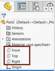
These are hidden by default, but in figure \(\PageIndex{2}\), they are shown to illustrate the orientation of the default planes. The default planes all intersect to create an origin. One of these planes is usually the starting point for any part model. You start sketching on the plane that is best oriented to the orientation you wish to start creating your part.

SKETCHING ON PLANES
When starting a new part, you want to begin your first sketch on the plane that will show the most profile and detail of your part. If the most profile and detail exist in the front or back view for your part (such as for a pipe), then you should consider beginning on the front plane (Figure \(\PageIndex{3}\)). If the most profile and detail exist in the top or bottom view of your part (such as for a base plate), then you should consider beginning from the top plane (Figure \(\PageIndex{4}\)). If the most profile and detail exist in the right or left view of your part (such as for a wheel hub), then you should consider beginning from the right plane \(Figure (\PageIndex{5}\)).


STARTING A SKETCH FROM A DEFAULT PLANE
A sketch can be started from a default plane in a couple of ways such as from the menu bar and clicking on the “Sketch” button from the sketch tab and following the property manager directions. However, the quickest way to start a new sketch from a default plane, and really any plane or face, is to left or right click on the desired plane (in the FeatureManager Design Tree or Graphics Area) and select the “Sketch” Icon (Figure \(\PageIndex{6}\)). This puts you right into the sketch environment.
The sketch environment is to the SolidWorks User Interface like the inside of a house is to the rest of the outside world. Going into the Sketch Environment makes many features off limits; however, you have access to so many other new features in the sketch environment related to creating sketches. Just like the things you do inside a house are completely different from the things you do outside, the things you do inside the sketch environment are completely different from the things you would do outside the sketch environment.
Note: Many new users to SolidWorks frequently go into the sketch environment by accident without knowing it, and then are confused when they find out that they are no longer unable to complete the commands they are usually able to complete. If you find yourself unable to do things in SolidWorks you should be able to do, check to see if you are in the Sketch Environment.
SIGNS THAT YOU ARE IN THE SKETCH ENVIRONMENT
The first sign to know if you are in a sketch is to check the status bar. The status bar in the right-side portion should say “Editing Sketch…” for whatever sketch you are editing (Figure \(\PageIndex{7}\)).

The second sign is the in-context confirm and deny buttons in the upper right-hand corner of the Graphics Area (Figure \(\PageIndex{8}\)). The blue arrow button is to confirm changes made to a sketch; the red “X” is to deny, and discard changes made to a sketch.

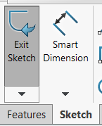
The third sign is your CommandManager changing to the Sketch tab and the Sketch button in the CommandManager being indented a dark grey shade (Figure \(\PageIndex{9}\)). Another, less noticeable sign, is your FeatureManager Design Tree features becoming greyed out. Under any other circumstances, you are NOT in the sketch environment and CANNOT do sketch related commands.
\(\PageIndex{1}\)
Let’s take some time to practice going in and out of the sketch environment and recognizing the various signs that we are in or not in the sketch environment.
- Open a SolidWorks new part.
- Enter and exit the sketch environment in the ways described above.
- Each time you are in the sketch environment, look for the three signs that indicate you are in the sketch environment.