13.1: Introduction to AC Motors
- Page ID
- 1466
\( \newcommand{\vecs}[1]{\overset { \scriptstyle \rightharpoonup} {\mathbf{#1}} } \)
\( \newcommand{\vecd}[1]{\overset{-\!-\!\rightharpoonup}{\vphantom{a}\smash {#1}}} \)
\( \newcommand{\dsum}{\displaystyle\sum\limits} \)
\( \newcommand{\dint}{\displaystyle\int\limits} \)
\( \newcommand{\dlim}{\displaystyle\lim\limits} \)
\( \newcommand{\id}{\mathrm{id}}\) \( \newcommand{\Span}{\mathrm{span}}\)
( \newcommand{\kernel}{\mathrm{null}\,}\) \( \newcommand{\range}{\mathrm{range}\,}\)
\( \newcommand{\RealPart}{\mathrm{Re}}\) \( \newcommand{\ImaginaryPart}{\mathrm{Im}}\)
\( \newcommand{\Argument}{\mathrm{Arg}}\) \( \newcommand{\norm}[1]{\| #1 \|}\)
\( \newcommand{\inner}[2]{\langle #1, #2 \rangle}\)
\( \newcommand{\Span}{\mathrm{span}}\)
\( \newcommand{\id}{\mathrm{id}}\)
\( \newcommand{\Span}{\mathrm{span}}\)
\( \newcommand{\kernel}{\mathrm{null}\,}\)
\( \newcommand{\range}{\mathrm{range}\,}\)
\( \newcommand{\RealPart}{\mathrm{Re}}\)
\( \newcommand{\ImaginaryPart}{\mathrm{Im}}\)
\( \newcommand{\Argument}{\mathrm{Arg}}\)
\( \newcommand{\norm}[1]{\| #1 \|}\)
\( \newcommand{\inner}[2]{\langle #1, #2 \rangle}\)
\( \newcommand{\Span}{\mathrm{span}}\) \( \newcommand{\AA}{\unicode[.8,0]{x212B}}\)
\( \newcommand{\vectorA}[1]{\vec{#1}} % arrow\)
\( \newcommand{\vectorAt}[1]{\vec{\text{#1}}} % arrow\)
\( \newcommand{\vectorB}[1]{\overset { \scriptstyle \rightharpoonup} {\mathbf{#1}} } \)
\( \newcommand{\vectorC}[1]{\textbf{#1}} \)
\( \newcommand{\vectorD}[1]{\overrightarrow{#1}} \)
\( \newcommand{\vectorDt}[1]{\overrightarrow{\text{#1}}} \)
\( \newcommand{\vectE}[1]{\overset{-\!-\!\rightharpoonup}{\vphantom{a}\smash{\mathbf {#1}}}} \)
\( \newcommand{\vecs}[1]{\overset { \scriptstyle \rightharpoonup} {\mathbf{#1}} } \)
\(\newcommand{\longvect}{\overrightarrow}\)
\( \newcommand{\vecd}[1]{\overset{-\!-\!\rightharpoonup}{\vphantom{a}\smash {#1}}} \)
\(\newcommand{\avec}{\mathbf a}\) \(\newcommand{\bvec}{\mathbf b}\) \(\newcommand{\cvec}{\mathbf c}\) \(\newcommand{\dvec}{\mathbf d}\) \(\newcommand{\dtil}{\widetilde{\mathbf d}}\) \(\newcommand{\evec}{\mathbf e}\) \(\newcommand{\fvec}{\mathbf f}\) \(\newcommand{\nvec}{\mathbf n}\) \(\newcommand{\pvec}{\mathbf p}\) \(\newcommand{\qvec}{\mathbf q}\) \(\newcommand{\svec}{\mathbf s}\) \(\newcommand{\tvec}{\mathbf t}\) \(\newcommand{\uvec}{\mathbf u}\) \(\newcommand{\vvec}{\mathbf v}\) \(\newcommand{\wvec}{\mathbf w}\) \(\newcommand{\xvec}{\mathbf x}\) \(\newcommand{\yvec}{\mathbf y}\) \(\newcommand{\zvec}{\mathbf z}\) \(\newcommand{\rvec}{\mathbf r}\) \(\newcommand{\mvec}{\mathbf m}\) \(\newcommand{\zerovec}{\mathbf 0}\) \(\newcommand{\onevec}{\mathbf 1}\) \(\newcommand{\real}{\mathbb R}\) \(\newcommand{\twovec}[2]{\left[\begin{array}{r}#1 \\ #2 \end{array}\right]}\) \(\newcommand{\ctwovec}[2]{\left[\begin{array}{c}#1 \\ #2 \end{array}\right]}\) \(\newcommand{\threevec}[3]{\left[\begin{array}{r}#1 \\ #2 \\ #3 \end{array}\right]}\) \(\newcommand{\cthreevec}[3]{\left[\begin{array}{c}#1 \\ #2 \\ #3 \end{array}\right]}\) \(\newcommand{\fourvec}[4]{\left[\begin{array}{r}#1 \\ #2 \\ #3 \\ #4 \end{array}\right]}\) \(\newcommand{\cfourvec}[4]{\left[\begin{array}{c}#1 \\ #2 \\ #3 \\ #4 \end{array}\right]}\) \(\newcommand{\fivevec}[5]{\left[\begin{array}{r}#1 \\ #2 \\ #3 \\ #4 \\ #5 \\ \end{array}\right]}\) \(\newcommand{\cfivevec}[5]{\left[\begin{array}{c}#1 \\ #2 \\ #3 \\ #4 \\ #5 \\ \end{array}\right]}\) \(\newcommand{\mattwo}[4]{\left[\begin{array}{rr}#1 \amp #2 \\ #3 \amp #4 \\ \end{array}\right]}\) \(\newcommand{\laspan}[1]{\text{Span}\{#1\}}\) \(\newcommand{\bcal}{\cal B}\) \(\newcommand{\ccal}{\cal C}\) \(\newcommand{\scal}{\cal S}\) \(\newcommand{\wcal}{\cal W}\) \(\newcommand{\ecal}{\cal E}\) \(\newcommand{\coords}[2]{\left\{#1\right\}_{#2}}\) \(\newcommand{\gray}[1]{\color{gray}{#1}}\) \(\newcommand{\lgray}[1]{\color{lightgray}{#1}}\) \(\newcommand{\rank}{\operatorname{rank}}\) \(\newcommand{\row}{\text{Row}}\) \(\newcommand{\col}{\text{Col}}\) \(\renewcommand{\row}{\text{Row}}\) \(\newcommand{\nul}{\text{Nul}}\) \(\newcommand{\var}{\text{Var}}\) \(\newcommand{\corr}{\text{corr}}\) \(\newcommand{\len}[1]{\left|#1\right|}\) \(\newcommand{\bbar}{\overline{\bvec}}\) \(\newcommand{\bhat}{\widehat{\bvec}}\) \(\newcommand{\bperp}{\bvec^\perp}\) \(\newcommand{\xhat}{\widehat{\xvec}}\) \(\newcommand{\vhat}{\widehat{\vvec}}\) \(\newcommand{\uhat}{\widehat{\uvec}}\) \(\newcommand{\what}{\widehat{\wvec}}\) \(\newcommand{\Sighat}{\widehat{\Sigma}}\) \(\newcommand{\lt}{<}\) \(\newcommand{\gt}{>}\) \(\newcommand{\amp}{&}\) \(\definecolor{fillinmathshade}{gray}{0.9}\)After the introduction of the DC electrical distribution system by Edison in the United States, a gradual transition to the more economical AC system commenced. Lighting worked as well on AC as on DC. Transmission of electrical energy covered longer distances at lower loss with alternating current. However, motors were a problem with alternating current. Initially, AC motors were constructed like DC motors. Numerous problems were encountered due to changing magnetic fields, as compared to the static fields in DC motor motor field coils.

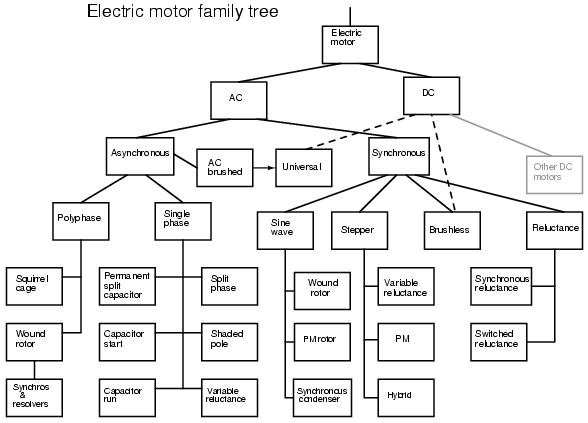
AC electric motor family diagram.
Charles P. Steinmetz contributed to solving these problems with his investigation of hysteresis losses in iron armatures. Nikola Tesla envisioned an entirely new type of motor when he visualized a spinning turbine, not spun by water or steam, but by a rotating magnetic field. His new type of motor, the AC induction motor, is the workhorse of industry to this day. Its ruggedness and simplicity (Figure above) make for long life, high reliability, and low maintenance. Yet small brushed AC motors, similar to the DC variety, persist in small appliances along with small Tesla induction motors. Above one horsepower (750 W), the Tesla motor reigns supreme.
Modern solid state electronic circuits drive brushless DC motors with AC waveforms generated from a DC source. The brushless DC motor, actually an AC motor, is replacing the conventional brushed DC motor in many applications. And, the stepper motor, a digital version of motor, is driven by alternating current square waves, again, generated by solid state circuitry Figure above shows the family tree of the AC motors described in this chapter.
Cruise ships and other large vessels replace reduction geared drive shafts with large multi-megawatt generators and motors. Such has been the case with diesel-electric locomotives on a smaller scale for many years.

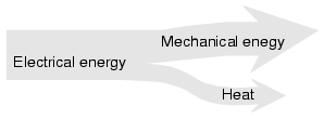
Motor system level diagram.
At the system level, (Figure above) a motor takes in electrical energy in terms of a potential difference and a current flow, converting it to mechanical work. Alas, electric motors are not 100% efficient. Some of the electric energy is lost to heat, another form of energy, due to I2R losses in the motor windings. The heat is an undesired byproduct of the conversion. It must be removed from the motor and may adversely affect longevity. Thus, one goal is to maximize motor efficiency, reducing the heat loss. AC motors also have some losses not encountered by DC motors: hysteresis and eddy currents.
Hysteresis and Eddy Current
Early designers of AC motors encountered problems traced to losses unique to alternating current magnetics. These problems were encountered when adapting DC motors to AC operation. Though few AC motors today bear any resemblance to DC motors, these problems had to be solved before AC motors of any type could be properly designed before they were built.
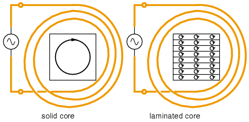
Both rotor and stator cores of AC motors are composed of a stack of insulated laminations. The laminations are coated with insulating varnish before stacking and bolting into the final form. Eddy currents are minimized by breaking the potential conductive loop into smaller less lossy segments. (Figure below) The current loops look like shorted transformer secondary turns. The thin isolated laminations break these loops. Also, the silicon (a semiconductor) added to the alloy used in the laminations increases electrical resistance which decreases the magnitude of eddy currents.

Eddy currents in iron cores.
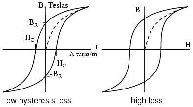
If the laminations are made of silicon alloy grain oriented steel, hysteresis losses are minimized. Magnetic hysteresis is a lagging behind of magnetic field strength as compared to magnetizing force. If a soft iron nail is temporarily magnetized by a solenoid, one would expect the nail to lose the magnetic field once the solenoid is de-energized. However, a small amount of residual magnetization, Br due to hysteresis remains. (Figure below) An alternating current has to expend energy, -Hc the coercive force, in overcoming this residual magnetization before it can magnetize the core back to zero, let alone in the opposite direction. Hysteresis loss is encountered each time the polarity of the AC reverses. The loss is proportional to the area enclosed by the hysteresis loop on the B-H curve. “Soft” iron alloys have lower losses than “hard” high carbon steel alloys. Silicon grain oriented steel, 4% silicon, rolled to preferentially orient the grain or crystalline structure, has still lower losses.

Hysteresis curves for low and high loss alloys. Once Steinmetz’s Laws of hysteresis could predict iron core losses, it was possible to design AC motors which performed as designed. This was akin to being able to design a bridge ahead of time that would not collapse once it was actually built. This knowledge of eddy current and hysteresis was first applied to building AC commutator motors similar to their DC counterparts. Today this is but a minor category of AC motors. Others invented new types of AC motors bearing little resemblance to their DC kin.


