13.12: AC Commutator Motors
- Page ID
- 1477
\( \newcommand{\vecs}[1]{\overset { \scriptstyle \rightharpoonup} {\mathbf{#1}} } \)
\( \newcommand{\vecd}[1]{\overset{-\!-\!\rightharpoonup}{\vphantom{a}\smash {#1}}} \)
\( \newcommand{\dsum}{\displaystyle\sum\limits} \)
\( \newcommand{\dint}{\displaystyle\int\limits} \)
\( \newcommand{\dlim}{\displaystyle\lim\limits} \)
\( \newcommand{\id}{\mathrm{id}}\) \( \newcommand{\Span}{\mathrm{span}}\)
( \newcommand{\kernel}{\mathrm{null}\,}\) \( \newcommand{\range}{\mathrm{range}\,}\)
\( \newcommand{\RealPart}{\mathrm{Re}}\) \( \newcommand{\ImaginaryPart}{\mathrm{Im}}\)
\( \newcommand{\Argument}{\mathrm{Arg}}\) \( \newcommand{\norm}[1]{\| #1 \|}\)
\( \newcommand{\inner}[2]{\langle #1, #2 \rangle}\)
\( \newcommand{\Span}{\mathrm{span}}\)
\( \newcommand{\id}{\mathrm{id}}\)
\( \newcommand{\Span}{\mathrm{span}}\)
\( \newcommand{\kernel}{\mathrm{null}\,}\)
\( \newcommand{\range}{\mathrm{range}\,}\)
\( \newcommand{\RealPart}{\mathrm{Re}}\)
\( \newcommand{\ImaginaryPart}{\mathrm{Im}}\)
\( \newcommand{\Argument}{\mathrm{Arg}}\)
\( \newcommand{\norm}[1]{\| #1 \|}\)
\( \newcommand{\inner}[2]{\langle #1, #2 \rangle}\)
\( \newcommand{\Span}{\mathrm{span}}\) \( \newcommand{\AA}{\unicode[.8,0]{x212B}}\)
\( \newcommand{\vectorA}[1]{\vec{#1}} % arrow\)
\( \newcommand{\vectorAt}[1]{\vec{\text{#1}}} % arrow\)
\( \newcommand{\vectorB}[1]{\overset { \scriptstyle \rightharpoonup} {\mathbf{#1}} } \)
\( \newcommand{\vectorC}[1]{\textbf{#1}} \)
\( \newcommand{\vectorD}[1]{\overrightarrow{#1}} \)
\( \newcommand{\vectorDt}[1]{\overrightarrow{\text{#1}}} \)
\( \newcommand{\vectE}[1]{\overset{-\!-\!\rightharpoonup}{\vphantom{a}\smash{\mathbf {#1}}}} \)
\( \newcommand{\vecs}[1]{\overset { \scriptstyle \rightharpoonup} {\mathbf{#1}} } \)
\(\newcommand{\longvect}{\overrightarrow}\)
\( \newcommand{\vecd}[1]{\overset{-\!-\!\rightharpoonup}{\vphantom{a}\smash {#1}}} \)
\(\newcommand{\avec}{\mathbf a}\) \(\newcommand{\bvec}{\mathbf b}\) \(\newcommand{\cvec}{\mathbf c}\) \(\newcommand{\dvec}{\mathbf d}\) \(\newcommand{\dtil}{\widetilde{\mathbf d}}\) \(\newcommand{\evec}{\mathbf e}\) \(\newcommand{\fvec}{\mathbf f}\) \(\newcommand{\nvec}{\mathbf n}\) \(\newcommand{\pvec}{\mathbf p}\) \(\newcommand{\qvec}{\mathbf q}\) \(\newcommand{\svec}{\mathbf s}\) \(\newcommand{\tvec}{\mathbf t}\) \(\newcommand{\uvec}{\mathbf u}\) \(\newcommand{\vvec}{\mathbf v}\) \(\newcommand{\wvec}{\mathbf w}\) \(\newcommand{\xvec}{\mathbf x}\) \(\newcommand{\yvec}{\mathbf y}\) \(\newcommand{\zvec}{\mathbf z}\) \(\newcommand{\rvec}{\mathbf r}\) \(\newcommand{\mvec}{\mathbf m}\) \(\newcommand{\zerovec}{\mathbf 0}\) \(\newcommand{\onevec}{\mathbf 1}\) \(\newcommand{\real}{\mathbb R}\) \(\newcommand{\twovec}[2]{\left[\begin{array}{r}#1 \\ #2 \end{array}\right]}\) \(\newcommand{\ctwovec}[2]{\left[\begin{array}{c}#1 \\ #2 \end{array}\right]}\) \(\newcommand{\threevec}[3]{\left[\begin{array}{r}#1 \\ #2 \\ #3 \end{array}\right]}\) \(\newcommand{\cthreevec}[3]{\left[\begin{array}{c}#1 \\ #2 \\ #3 \end{array}\right]}\) \(\newcommand{\fourvec}[4]{\left[\begin{array}{r}#1 \\ #2 \\ #3 \\ #4 \end{array}\right]}\) \(\newcommand{\cfourvec}[4]{\left[\begin{array}{c}#1 \\ #2 \\ #3 \\ #4 \end{array}\right]}\) \(\newcommand{\fivevec}[5]{\left[\begin{array}{r}#1 \\ #2 \\ #3 \\ #4 \\ #5 \\ \end{array}\right]}\) \(\newcommand{\cfivevec}[5]{\left[\begin{array}{c}#1 \\ #2 \\ #3 \\ #4 \\ #5 \\ \end{array}\right]}\) \(\newcommand{\mattwo}[4]{\left[\begin{array}{rr}#1 \amp #2 \\ #3 \amp #4 \\ \end{array}\right]}\) \(\newcommand{\laspan}[1]{\text{Span}\{#1\}}\) \(\newcommand{\bcal}{\cal B}\) \(\newcommand{\ccal}{\cal C}\) \(\newcommand{\scal}{\cal S}\) \(\newcommand{\wcal}{\cal W}\) \(\newcommand{\ecal}{\cal E}\) \(\newcommand{\coords}[2]{\left\{#1\right\}_{#2}}\) \(\newcommand{\gray}[1]{\color{gray}{#1}}\) \(\newcommand{\lgray}[1]{\color{lightgray}{#1}}\) \(\newcommand{\rank}{\operatorname{rank}}\) \(\newcommand{\row}{\text{Row}}\) \(\newcommand{\col}{\text{Col}}\) \(\renewcommand{\row}{\text{Row}}\) \(\newcommand{\nul}{\text{Nul}}\) \(\newcommand{\var}{\text{Var}}\) \(\newcommand{\corr}{\text{corr}}\) \(\newcommand{\len}[1]{\left|#1\right|}\) \(\newcommand{\bbar}{\overline{\bvec}}\) \(\newcommand{\bhat}{\widehat{\bvec}}\) \(\newcommand{\bperp}{\bvec^\perp}\) \(\newcommand{\xhat}{\widehat{\xvec}}\) \(\newcommand{\vhat}{\widehat{\vvec}}\) \(\newcommand{\uhat}{\widehat{\uvec}}\) \(\newcommand{\what}{\widehat{\wvec}}\) \(\newcommand{\Sighat}{\widehat{\Sigma}}\) \(\newcommand{\lt}{<}\) \(\newcommand{\gt}{>}\) \(\newcommand{\amp}{&}\) \(\definecolor{fillinmathshade}{gray}{0.9}\)Charles Proteus Steinmetz’s first job after arriving in America was to investigate problems encountered in the design of the alternating current version of the brushed commutator motor. The situation was so bad that motors could not be designed ahead of the actual construction. The success or failure of a motor design was not known until after it was actually built at great expense and tested. He formulated the laws of magnetic hysteresis in finding a solution. Hysteresis is a lagging behind of the magnetic field strength as compared to the magnetizing force. This produces a loss not present in DC magnetics. Low hysteresis alloys and breaking the alloy into thin insulated laminations made it possible to accurately design AC commutator motors before building.
AC commutator motors, like comparable DC motors, have higher starting torque and higher speed than AC induction motors. The series motor operates well above the synchronous speed of a conventional AC motor. AC commutator motors may be either single-phase or poly-phase. The single-phase AC version suffers a double line frequency torque pulsation, not present in poly-phase motor. Since a commutator motor can operate at much higher speed than an induction motor, it can output more power than a similar size induction motor. However commutator motors are not as maintenance free as induction motors, due to brush and commutator wear.
Single phase series motor
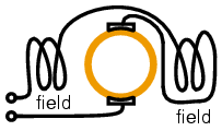
If a DC series motor equipped with a laminated field is connected to AC, the lagging reactance of the field coil will considerably reduce the field current. While such a motor will rotate, operation is marginal. While starting, armature windings connected to commutator segments shorted by the brushes look like shorted transformer turns to the field. This results in considerable arcing and sparking at the brushes as the armature begins to turn. This is less of a problem as speed increases, which shares the arcing and sparking between commutator segments The lagging reactance and arcing brushes are only tolerable in very small uncompensated series AC motors operated at high speed. Series AC motors smaller than hand drills and kitchen mixers may be uncompensated. (Figure below)

Uncompensated series AC motor.
Compensated series motor
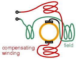
The arcing and sparking is mitigated by placing a compensating winding the stator in series with the armature positioned so that its magnetomotive force (mmf) cancels out the armature AC mmf. (Figure below) A smaller motor air gap and fewer field turns reduces lagging reactance in series with the armature improving the power factor. All but very small AC commutator motors employ compensating windings. Motors as large as those employed in a kitchen mixer, or larger, use compensated stator windings.

Compensated series AC motor.
Universal motor
It is possible to design small (under 300 watts) universal motors which run from either DC or AC. Very small universal motors may be uncompensated. Larger higher speed universal motors use a compensating winding. A motor will run slower on AC than DC due to the reactance encountered with AC. However, the peaks of the sine waves saturate the magnetic path reducing total flux below the DC value, increasing the speed of the “series” motor. Thus, the offsetting effects result in a nearly constant speed from DC to 60 Hz. Small line operated appliances, such as drills, vacuum cleaners, and mixers, requiring 3000 to 10,000 rpm use universal motors. Though, the development of solid state rectifiers and inexpensive permanent magnets is making the DC permanent magnet motor a viable alternative.
Repulsion motor
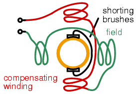
A repulsion motor (Figure below) consists of a field directly connected to the AC line voltage and a pair of shorted brushes offset by 15oto 25o from the field axis. The field induces a current flow into the shorted armature whose magnetic field opposes that of the field coils. Speed can be controlled by rotating the brushes with respect to the field axis. This motor has superior commutation below synchronous speed, inferior commutation above synchronous speed. Low starting current produces high starting torque.

Repulsion AC motor.
Repulsion start induction motor
When an induction motor drives a hard starting load like a compressor, the high starting torque of the repulsion motor may be put to use. The induction motor rotor windings are brought out to commutator segments for starting by a pair of shorted brushes. At near running speed, a centrifugal switch shorts out all commutator segments, giving the effect of a squirrel cage rotor . The brushes may also be lifted to prolong bush life. Starting torque is 300% to 600% of the full speed value as compared to under 200% for a pure induction motor.
Summary: AC commutator motors
- The single phase series motor is an attempt to build a motor like a DC commutator motor. The resulting motor is only practical in the smallest sizes.
- The addition of a compensating winding yields the compensated series motor, overcoming excessive commutator sparking. Most AC commutator motors are this type. At high speed this motor provides more power than a same-size induction motor, but is not maintenance free.
- It is possible to produce small appliance motors powered by either AC or DC. This is known as a universal motor.
- The AC line is directly connected to the stator of a repulsion motor with the commutator shorted by the brushes.
- Retractable shorted brushes may start a wound rotor induction motor. This is known as a repulsion start induction motor.


