11.3: Synchronous Counters
- Page ID
- 979
\( \newcommand{\vecs}[1]{\overset { \scriptstyle \rightharpoonup} {\mathbf{#1}} } \)
\( \newcommand{\vecd}[1]{\overset{-\!-\!\rightharpoonup}{\vphantom{a}\smash {#1}}} \)
\( \newcommand{\dsum}{\displaystyle\sum\limits} \)
\( \newcommand{\dint}{\displaystyle\int\limits} \)
\( \newcommand{\dlim}{\displaystyle\lim\limits} \)
\( \newcommand{\id}{\mathrm{id}}\) \( \newcommand{\Span}{\mathrm{span}}\)
( \newcommand{\kernel}{\mathrm{null}\,}\) \( \newcommand{\range}{\mathrm{range}\,}\)
\( \newcommand{\RealPart}{\mathrm{Re}}\) \( \newcommand{\ImaginaryPart}{\mathrm{Im}}\)
\( \newcommand{\Argument}{\mathrm{Arg}}\) \( \newcommand{\norm}[1]{\| #1 \|}\)
\( \newcommand{\inner}[2]{\langle #1, #2 \rangle}\)
\( \newcommand{\Span}{\mathrm{span}}\)
\( \newcommand{\id}{\mathrm{id}}\)
\( \newcommand{\Span}{\mathrm{span}}\)
\( \newcommand{\kernel}{\mathrm{null}\,}\)
\( \newcommand{\range}{\mathrm{range}\,}\)
\( \newcommand{\RealPart}{\mathrm{Re}}\)
\( \newcommand{\ImaginaryPart}{\mathrm{Im}}\)
\( \newcommand{\Argument}{\mathrm{Arg}}\)
\( \newcommand{\norm}[1]{\| #1 \|}\)
\( \newcommand{\inner}[2]{\langle #1, #2 \rangle}\)
\( \newcommand{\Span}{\mathrm{span}}\) \( \newcommand{\AA}{\unicode[.8,0]{x212B}}\)
\( \newcommand{\vectorA}[1]{\vec{#1}} % arrow\)
\( \newcommand{\vectorAt}[1]{\vec{\text{#1}}} % arrow\)
\( \newcommand{\vectorB}[1]{\overset { \scriptstyle \rightharpoonup} {\mathbf{#1}} } \)
\( \newcommand{\vectorC}[1]{\textbf{#1}} \)
\( \newcommand{\vectorD}[1]{\overrightarrow{#1}} \)
\( \newcommand{\vectorDt}[1]{\overrightarrow{\text{#1}}} \)
\( \newcommand{\vectE}[1]{\overset{-\!-\!\rightharpoonup}{\vphantom{a}\smash{\mathbf {#1}}}} \)
\( \newcommand{\vecs}[1]{\overset { \scriptstyle \rightharpoonup} {\mathbf{#1}} } \)
\(\newcommand{\longvect}{\overrightarrow}\)
\( \newcommand{\vecd}[1]{\overset{-\!-\!\rightharpoonup}{\vphantom{a}\smash {#1}}} \)
\(\newcommand{\avec}{\mathbf a}\) \(\newcommand{\bvec}{\mathbf b}\) \(\newcommand{\cvec}{\mathbf c}\) \(\newcommand{\dvec}{\mathbf d}\) \(\newcommand{\dtil}{\widetilde{\mathbf d}}\) \(\newcommand{\evec}{\mathbf e}\) \(\newcommand{\fvec}{\mathbf f}\) \(\newcommand{\nvec}{\mathbf n}\) \(\newcommand{\pvec}{\mathbf p}\) \(\newcommand{\qvec}{\mathbf q}\) \(\newcommand{\svec}{\mathbf s}\) \(\newcommand{\tvec}{\mathbf t}\) \(\newcommand{\uvec}{\mathbf u}\) \(\newcommand{\vvec}{\mathbf v}\) \(\newcommand{\wvec}{\mathbf w}\) \(\newcommand{\xvec}{\mathbf x}\) \(\newcommand{\yvec}{\mathbf y}\) \(\newcommand{\zvec}{\mathbf z}\) \(\newcommand{\rvec}{\mathbf r}\) \(\newcommand{\mvec}{\mathbf m}\) \(\newcommand{\zerovec}{\mathbf 0}\) \(\newcommand{\onevec}{\mathbf 1}\) \(\newcommand{\real}{\mathbb R}\) \(\newcommand{\twovec}[2]{\left[\begin{array}{r}#1 \\ #2 \end{array}\right]}\) \(\newcommand{\ctwovec}[2]{\left[\begin{array}{c}#1 \\ #2 \end{array}\right]}\) \(\newcommand{\threevec}[3]{\left[\begin{array}{r}#1 \\ #2 \\ #3 \end{array}\right]}\) \(\newcommand{\cthreevec}[3]{\left[\begin{array}{c}#1 \\ #2 \\ #3 \end{array}\right]}\) \(\newcommand{\fourvec}[4]{\left[\begin{array}{r}#1 \\ #2 \\ #3 \\ #4 \end{array}\right]}\) \(\newcommand{\cfourvec}[4]{\left[\begin{array}{c}#1 \\ #2 \\ #3 \\ #4 \end{array}\right]}\) \(\newcommand{\fivevec}[5]{\left[\begin{array}{r}#1 \\ #2 \\ #3 \\ #4 \\ #5 \\ \end{array}\right]}\) \(\newcommand{\cfivevec}[5]{\left[\begin{array}{c}#1 \\ #2 \\ #3 \\ #4 \\ #5 \\ \end{array}\right]}\) \(\newcommand{\mattwo}[4]{\left[\begin{array}{rr}#1 \amp #2 \\ #3 \amp #4 \\ \end{array}\right]}\) \(\newcommand{\laspan}[1]{\text{Span}\{#1\}}\) \(\newcommand{\bcal}{\cal B}\) \(\newcommand{\ccal}{\cal C}\) \(\newcommand{\scal}{\cal S}\) \(\newcommand{\wcal}{\cal W}\) \(\newcommand{\ecal}{\cal E}\) \(\newcommand{\coords}[2]{\left\{#1\right\}_{#2}}\) \(\newcommand{\gray}[1]{\color{gray}{#1}}\) \(\newcommand{\lgray}[1]{\color{lightgray}{#1}}\) \(\newcommand{\rank}{\operatorname{rank}}\) \(\newcommand{\row}{\text{Row}}\) \(\newcommand{\col}{\text{Col}}\) \(\renewcommand{\row}{\text{Row}}\) \(\newcommand{\nul}{\text{Nul}}\) \(\newcommand{\var}{\text{Var}}\) \(\newcommand{\corr}{\text{corr}}\) \(\newcommand{\len}[1]{\left|#1\right|}\) \(\newcommand{\bbar}{\overline{\bvec}}\) \(\newcommand{\bhat}{\widehat{\bvec}}\) \(\newcommand{\bperp}{\bvec^\perp}\) \(\newcommand{\xhat}{\widehat{\xvec}}\) \(\newcommand{\vhat}{\widehat{\vvec}}\) \(\newcommand{\uhat}{\widehat{\uvec}}\) \(\newcommand{\what}{\widehat{\wvec}}\) \(\newcommand{\Sighat}{\widehat{\Sigma}}\) \(\newcommand{\lt}{<}\) \(\newcommand{\gt}{>}\) \(\newcommand{\amp}{&}\) \(\definecolor{fillinmathshade}{gray}{0.9}\)What is a Synchronous Counter?
A synchronous counter, in contrast to an asynchronous counter, is one whose output bits change state simultaneously, with no ripple. The only way we can build such a counter circuit from J-K flip-flops is to connect all the clock inputs together, so that each and every flip-flop receives the exact same clock pulse at the exact same time:
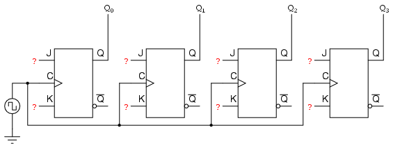
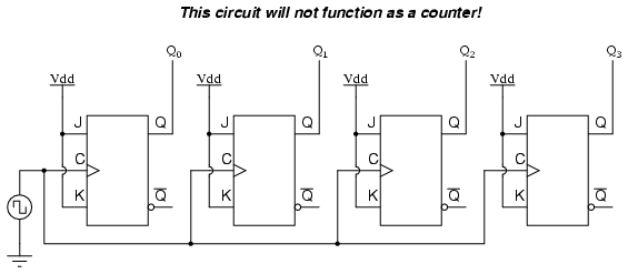
Now, the question is, what do we do with the J and K inputs? We know that we still have to maintain the same divide-by-two frequency pattern in order to count in a binary sequence, and that this pattern is best achieved utilizing the “toggle” mode of the flip-flop, so the fact that the J and K inputs must both be (at times) “high” is clear. However, if we simply connect all the J and K inputs to the positive rail of the power supply as we did in the asynchronous circuit, this would clearly not work because all the flip-flops would toggle at the same time: with each and every clock pulse!
Let’s examine the four-bit binary counting sequence again, and see if there are any other patterns that predict the toggling of a bit. Asynchronous counter circuit design is based on the fact that each bit toggle happens at the same time that the preceding bit toggles from a “high” to a “low” (from 1 to 0). Since we cannot clock the toggling of a bit based on the toggling of a previous bit in a synchronous counter circuit (to do so would create a ripple effect) we must find some other pattern in the counting sequence that can be used to trigger a bit toggle:
Examining the four-bit binary count sequence, another predictive pattern can be seen. Notice that just before a bit toggles, all preceding bits are “high:”

This pattern is also something we can exploit in designing a counter circuit.
Synchronous “Up” Counter
If we enable each J-K flip-flop to toggle based on whether or not all preceding flip-flop outputs (Q) are “high,” we can obtain the same counting sequence as the asynchronous circuit without the ripple effect, since each flip-flop in this circuit will be clocked at exactly the same time:
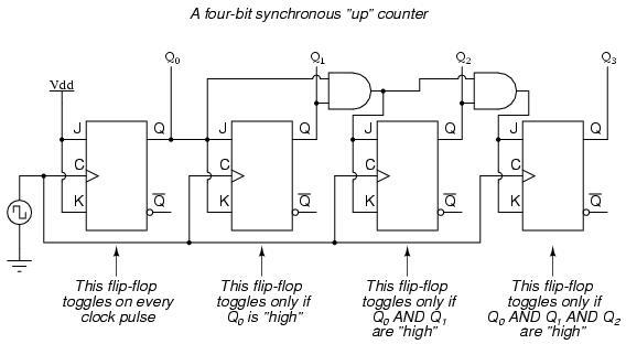
The result is a four-bit synchronous “up” counter. Each of the higher-order flip-flops are made ready to toggle (both J and K inputs “high”) if the Q outputs of all previous flip-flops are “high.” Otherwise, the J and K inputs for that flip-flop will both be “low,” placing it into the “latch” mode where it will maintain its present output state at the next clock pulse. Since the first (LSB) flip-flop needs to toggle at every clock pulse, its J and K inputs are connected to Vcc or Vdd, where they will be “high” all the time. The next flip-flop need only “recognize” that the first flip-flop’s Q output is high to be made ready to toggle, so no AND gate is needed. However, the remaining flip-flops should be made ready to toggle only when all lower-order output bits are “high,” thus the need for AND gates.
Synchronous “Down” Counter
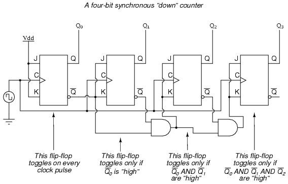
To make a synchronous “down” counter, we need to build the circuit to recognize the appropriate bit patterns predicting each toggle state while counting down. Not surprisingly, when we examine the four-bit binary count sequence, we see that all preceding bits are “low” prior to a toggle (following the sequence from bottom to top):

Since each J-K flip-flop comes equipped with a Q’ output as well as a Q output, we can use the Q’ outputs to enable the toggle mode on each succeeding flip-flop, being that each Q’ will be “high” every time that the respective Q is “low:”
Counter Circuit with Selectable “up” and “down” Count Modes
Taking this idea one step further, we can build a counter circuit with selectable between “up” and “down” count modes by having dual lines of AND gates detecting the appropriate bit conditions for an “up” and a “down” counting sequence, respectively, then use OR gates to combine the AND gate outputs to the J and K inputs of each succeeding flip-flop:

This circuit isn’t as complex as it might first appear. The Up/Down control input line simply enables either the upper string or lower string of AND gates to pass the Q/Q’ outputs to the succeeding stages of flip-flops. If the Up/Down control line is “high,” the top AND gates become enabled, and the circuit functions exactly the same as the first (“up”) synchronous counter circuit shown in this section. If the Up/Down control line is made “low,” the bottom AND gates become enabled, and the circuit functions identically to the second (“down” counter) circuit shown in this section.
To illustrate, here is a diagram showing the circuit in the “up” counting mode (all disabled circuitry shown in grey rather than black):

Here, shown in the “down” counting mode, with the same grey coloring representing disabled circuitry:

Up/down counter circuits are very useful devices. A common application is in machine motion control, where devices called rotary shaft encoders convert mechanical rotation into a series of electrical pulses, these pulses “clocking” a counter circuit to track total motion:
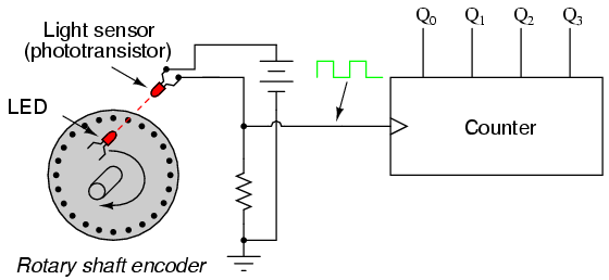
As the machine moves, it turns the encoder shaft, making and breaking the light beam between LED and phototransistor, thereby generating clock pulses to increment the counter circuit. Thus, the counter integrates, or accumulates, total motion of the shaft, serving as an electronic indication of how far the machine has moved. If all we care about is tracking total motion, and do not care to account for changes in the direction of motion, this arrangement will suffice. However, if we wish the counter to increment with one direction of motion and decrement with the reverse direction of motion, we must use an up/down counter, and an encoder/decoding circuit having the ability to discriminate between different directions.
If we re-design the encoder to have two sets of LED/photo transistor pairs, those pairs aligned such that their square-wave output signals are 90o out of phase with each other, we have what is known as a quadrature output encoder (the word “quadrature” simply refers to a 90o angular separation). A phase detection circuit may be made from a D-type flip-flop, to distinguish a clockwise pulse sequence from a counter-clockwise pulse sequence:
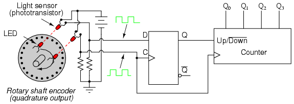
When the encoder rotates clockwise, the “D” input signal square-wave will lead the “C” input square-wave, meaning that the “D” input will already be “high” when the “C” transitions from “low” to “high,” thus settingthe D-type flip-flop (making the Q output “high”) with every clock pulse. A “high” Q output places the counter into the “Up” count mode, and any clock pulses received by the clock from the encoder (from either LED) will increment it. Conversely, when the encoder reverses rotation, the “D” input will lag behind the “C” input waveform, meaning that it will be “low” when the “C” waveform transitions from “low” to “high,” forcing the D-type flip-flop into the reset state (making the Q output “low”) with every clock pulse. This “low” signal commands the counter circuit to decrement with every clock pulse from the encoder.
This circuit, or something very much like it, is at the heart of every position-measuring circuit based on a pulse encoder sensor. Such applications are very common in robotics, CNC machine tool control, and other applications involving the measurement of reversible, mechanical motion.


