13.2: Troubleshooting principles
- Page ID
- 3511
\( \newcommand{\vecs}[1]{\overset { \scriptstyle \rightharpoonup} {\mathbf{#1}} } \)
\( \newcommand{\vecd}[1]{\overset{-\!-\!\rightharpoonup}{\vphantom{a}\smash {#1}}} \)
\( \newcommand{\id}{\mathrm{id}}\) \( \newcommand{\Span}{\mathrm{span}}\)
( \newcommand{\kernel}{\mathrm{null}\,}\) \( \newcommand{\range}{\mathrm{range}\,}\)
\( \newcommand{\RealPart}{\mathrm{Re}}\) \( \newcommand{\ImaginaryPart}{\mathrm{Im}}\)
\( \newcommand{\Argument}{\mathrm{Arg}}\) \( \newcommand{\norm}[1]{\| #1 \|}\)
\( \newcommand{\inner}[2]{\langle #1, #2 \rangle}\)
\( \newcommand{\Span}{\mathrm{span}}\)
\( \newcommand{\id}{\mathrm{id}}\)
\( \newcommand{\Span}{\mathrm{span}}\)
\( \newcommand{\kernel}{\mathrm{null}\,}\)
\( \newcommand{\range}{\mathrm{range}\,}\)
\( \newcommand{\RealPart}{\mathrm{Re}}\)
\( \newcommand{\ImaginaryPart}{\mathrm{Im}}\)
\( \newcommand{\Argument}{\mathrm{Arg}}\)
\( \newcommand{\norm}[1]{\| #1 \|}\)
\( \newcommand{\inner}[2]{\langle #1, #2 \rangle}\)
\( \newcommand{\Span}{\mathrm{span}}\) \( \newcommand{\AA}{\unicode[.8,0]{x212B}}\)
\( \newcommand{\vectorA}[1]{\vec{#1}} % arrow\)
\( \newcommand{\vectorAt}[1]{\vec{\text{#1}}} % arrow\)
\( \newcommand{\vectorB}[1]{\overset { \scriptstyle \rightharpoonup} {\mathbf{#1}} } \)
\( \newcommand{\vectorC}[1]{\textbf{#1}} \)
\( \newcommand{\vectorD}[1]{\overrightarrow{#1}} \)
\( \newcommand{\vectorDt}[1]{\overrightarrow{\text{#1}}} \)
\( \newcommand{\vectE}[1]{\overset{-\!-\!\rightharpoonup}{\vphantom{a}\smash{\mathbf {#1}}}} \)
\( \newcommand{\vecs}[1]{\overset { \scriptstyle \rightharpoonup} {\mathbf{#1}} } \)
\( \newcommand{\vecd}[1]{\overset{-\!-\!\rightharpoonup}{\vphantom{a}\smash {#1}}} \)
\(\newcommand{\avec}{\mathbf a}\) \(\newcommand{\bvec}{\mathbf b}\) \(\newcommand{\cvec}{\mathbf c}\) \(\newcommand{\dvec}{\mathbf d}\) \(\newcommand{\dtil}{\widetilde{\mathbf d}}\) \(\newcommand{\evec}{\mathbf e}\) \(\newcommand{\fvec}{\mathbf f}\) \(\newcommand{\nvec}{\mathbf n}\) \(\newcommand{\pvec}{\mathbf p}\) \(\newcommand{\qvec}{\mathbf q}\) \(\newcommand{\svec}{\mathbf s}\) \(\newcommand{\tvec}{\mathbf t}\) \(\newcommand{\uvec}{\mathbf u}\) \(\newcommand{\vvec}{\mathbf v}\) \(\newcommand{\wvec}{\mathbf w}\) \(\newcommand{\xvec}{\mathbf x}\) \(\newcommand{\yvec}{\mathbf y}\) \(\newcommand{\zvec}{\mathbf z}\) \(\newcommand{\rvec}{\mathbf r}\) \(\newcommand{\mvec}{\mathbf m}\) \(\newcommand{\zerovec}{\mathbf 0}\) \(\newcommand{\onevec}{\mathbf 1}\) \(\newcommand{\real}{\mathbb R}\) \(\newcommand{\twovec}[2]{\left[\begin{array}{r}#1 \\ #2 \end{array}\right]}\) \(\newcommand{\ctwovec}[2]{\left[\begin{array}{c}#1 \\ #2 \end{array}\right]}\) \(\newcommand{\threevec}[3]{\left[\begin{array}{r}#1 \\ #2 \\ #3 \end{array}\right]}\) \(\newcommand{\cthreevec}[3]{\left[\begin{array}{c}#1 \\ #2 \\ #3 \end{array}\right]}\) \(\newcommand{\fourvec}[4]{\left[\begin{array}{r}#1 \\ #2 \\ #3 \\ #4 \end{array}\right]}\) \(\newcommand{\cfourvec}[4]{\left[\begin{array}{c}#1 \\ #2 \\ #3 \\ #4 \end{array}\right]}\) \(\newcommand{\fivevec}[5]{\left[\begin{array}{r}#1 \\ #2 \\ #3 \\ #4 \\ #5 \\ \end{array}\right]}\) \(\newcommand{\cfivevec}[5]{\left[\begin{array}{c}#1 \\ #2 \\ #3 \\ #4 \\ #5 \\ \end{array}\right]}\) \(\newcommand{\mattwo}[4]{\left[\begin{array}{rr}#1 \amp #2 \\ #3 \amp #4 \\ \end{array}\right]}\) \(\newcommand{\laspan}[1]{\text{Span}\{#1\}}\) \(\newcommand{\bcal}{\cal B}\) \(\newcommand{\ccal}{\cal C}\) \(\newcommand{\scal}{\cal S}\) \(\newcommand{\wcal}{\cal W}\) \(\newcommand{\ecal}{\cal E}\) \(\newcommand{\coords}[2]{\left\{#1\right\}_{#2}}\) \(\newcommand{\gray}[1]{\color{gray}{#1}}\) \(\newcommand{\lgray}[1]{\color{lightgray}{#1}}\) \(\newcommand{\rank}{\operatorname{rank}}\) \(\newcommand{\row}{\text{Row}}\) \(\newcommand{\col}{\text{Col}}\) \(\renewcommand{\row}{\text{Row}}\) \(\newcommand{\nul}{\text{Nul}}\) \(\newcommand{\var}{\text{Var}}\) \(\newcommand{\corr}{\text{corr}}\) \(\newcommand{\len}[1]{\left|#1\right|}\) \(\newcommand{\bbar}{\overline{\bvec}}\) \(\newcommand{\bhat}{\widehat{\bvec}}\) \(\newcommand{\bperp}{\bvec^\perp}\) \(\newcommand{\xhat}{\widehat{\xvec}}\) \(\newcommand{\vhat}{\widehat{\vvec}}\) \(\newcommand{\uhat}{\widehat{\uvec}}\) \(\newcommand{\what}{\widehat{\wvec}}\) \(\newcommand{\Sighat}{\widehat{\Sigma}}\) \(\newcommand{\lt}{<}\) \(\newcommand{\gt}{>}\) \(\newcommand{\amp}{&}\) \(\definecolor{fillinmathshade}{gray}{0.9}\)There are really only two rules for troubleshooting using a voltmeter. They are simple and always true:
- If you measure a voltage across a switch, the switch is open.
- If you measure a correct voltage across a load and the load doesn’t work, the load has failed.
With digital meters, voltage readings that are considered as zero will often indicate minimal voltage readings. For example, a minimal reading could indicate a very slight resistance across the switch contacts or even a meter inaccuracy when reading across a closed switch.
Notice that the first rule does not say that the switch is closed if you read zero volts across a switch. There are many situations in which you might read zero volts across an open switch.
The second rule indicates that the load has failed. This only means that the problem is with the load, and you don’t have to look anywhere else for the problem. The actual remedy still has to be determined. This may require a replacement of the load, but there may be other possibilities. For example, there may be an overload that needs resetting.
Always look for the easy fix first. Check components that are easily accessible first that might explain the symptom that you have observed. For example, one of the first checks is to verify the power supply.
Voltage tests
You can troubleshoot a problem using either volt or ohms tests. It is most practical to choose voltage testing. With a resistance test, you have to first disconnect the component being tested from the circuit. In other words, you may not really find the problem. While removing the wiring, you could jostle things and possibly change the circuit, which may temporarily remedy the problem.
When you use your voltmeter to troubleshoot, you will find either an open switch or a load that has failed. You may then remove the device and double-check it with your ohmmeter. You can do this without moving any wires and without changing the circuit in any way.
Voltage drops in series circuits
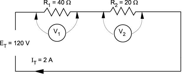
Consider the simple series circuit in Figure \(\PageIndex{1}\). In series circuits, the total voltage is the sum of the individual voltage drops in the circuit, and the equation E = IR is used to calculate the voltage drop across each resistor. Since the current is the same through each resistor, the voltage drop across each resistor is directly proportional to the resistance value. In other words, the greater the value of a resistor in a series circuit, the higher the voltage drop.
Example \(\PageIndex{1}\)
From the values given above, you can easily calculate the voltage drop across each resistor by:
Solution
E1 = I1 × R1 = 2 A × 40 Ω = 80 V
E2 = I2 × R2 = 2 A × 20 Ω = 40 V
The voltage drop of 80 V across the 40 Ω resistor is twice the voltage drop across the 20 Ω resistor.
Refer to Figure \(\PageIndex{2}\). If an open is introduced between resistors R1 and R2 (for example, by disconnecting a lead), current flow through the circuit is, of course, interrupted. If there is no current flow, the voltage drop across each resistive element is zero (since E = I × R).
However, the potential difference of the source still exists across the open. If a voltmeter is connected across the open, the reading is the same as if it were connected directly across the terminals of the supply source.
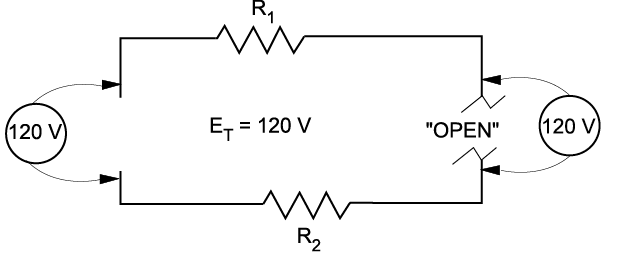
In a series lighting circuit, you could easily determine which lamp was burnt open simply by measuring the voltage across the lamp-holder terminals, in succession, until you have measured the total source voltage.
Caution!
 Since the source voltage still exists across the open in a series circuit, this represents a shock hazard. Be careful not to touch the live parts of the circuit!
Similarly, if a switch is opened, the full-source voltage will appear across the switch contacts. Even though the voltage across the load devices may be zero, if any of those loads are ahead of the switch, they will be energized with full voltage to ground.
Troubleshooting series components
Sometimes you will be required to troubleshoot a piece of equipment that has stopped working. The first thing you would check for is power. Is the breaker off? Is the switch off? Is there a general power outage?
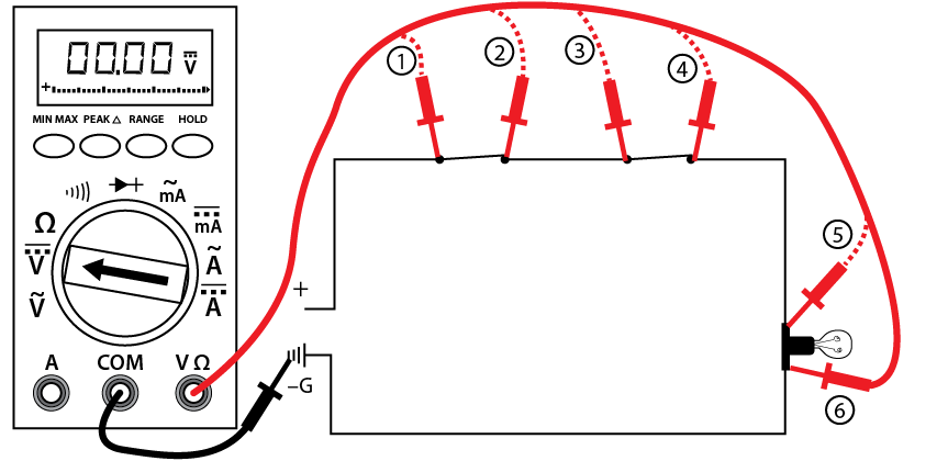
Once you have determined that power is still available, you can use the multimeter to locate the problem. Starting with the first component or the easiest one to check, work your way through the circuit until you reach the component that shows no voltage reading. This is known as hopscotch voltage readings. Figure 3 illustrates this process. The dashed line indicates where the probe has already been placed and removed.
Follow these steps to complete the voltage test procedures with an autorange meter:
- Set the selector dial to the type of current to be tested: AC or DC.
- Once you have determined that the load (shown as a lightbulb) is not working, check for voltage across the light first to verify rule #2 (i.e., if you measure a correct voltage across a load and the load doesn’t work, the load has failed.).
- If you have voltage across the light, then the light has failed. If there are zero volts across the light, then one of the switches or wiring connections in the circuit has failed. If you have a zero reading across the light, continue with the next steps.
- Place the black probe at a grounded component.
- Place the red probe and check for a voltage reading at each test point, starting at test point 1, verifying the power supply.
- Continue working your way through the circuit until you get a zero reading, which would indicate a break in the circuit just before that point.
- Reading at 2 = switch #1 closed, zero at 2 = switch #1 open
- Reading at 3 = wiring to switch #2 good, zero at 3 = wiring to switch #2 open
- Reading at 4 = switch #2 closed, zero at 4 = switch #2 open
- Reading at 5 = wiring to light good, zero at 5 = wiring to light open
- Reading at 6 = load is energized, zero at 6 = the load is open (although you have already checked the load in your first test). If you get to this stage and the load is energized, the only component left that must be faulty is the final wiring from the load to ground.
- Once the open in the circuit has been identified, you can de-energize the circuit,
- remove the component, and double-check the component with your ohmmeter.
- If this is the last test you are doing, turn the meter to “off” and store it in a safe place.
Testing resistance (ohms) with a digital multimeter
This test, using a digital multimeter, determines whether:
- an electrical circuit is complete or broken
- the resistance of a component matches the manufacturer’s specification
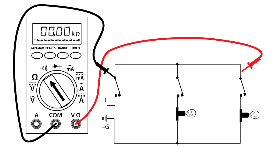
Follow these steps to complete the resistance test procedure:
- Make sure all power is off on the circuit you are testing.
- Make sure that the component that you are testing is isolated from the complete circuit. Either remove the component from the circuit or isolate it with an open switch.
- Set the selector dial to Ω.
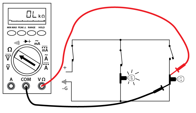
- Connect the test lead and probes to the component terminals as shown (Figure 4).
- Observe the readout window to obtain the Ω reading.
- Compare the results to the manufacturer’s Ω specifications. If the readings match the component, then resistance is not a problem.
- If the component is a load, there should be resistance that matches the manufacturer’s specs.
- If the reading is infinite (I) or overloaded (OL), the component is open.
- If the reading is zero, then the component is closed (if it is a load, this is an internal short).
- If this is the last test you are doing, turn the meter to “off” and store it in a safe place.
Note
 There may be other energized circuits even though the circuit you are working on is not energized. DO NOT TOUCH THE METER PROBES TO ANY ENERGIZED COMPONENTS WHEN TESTING FOR CONTINUITY. YOU MAY DAMAGE THE METER.
Continuity test
This is a quick audible alarm test using a digital multimeter to determine whether an electrical circuit or wire is complete or broken.
This test can be applied to a circuit as a whole or in sections—on individual components or sections of wiring. A break in continuity can be caused by mechanical damage, corrosion of components, or simply a switch being left open.
Follow these steps to complete the continuity test procedure with an autorange digital meter:
- Make sure all power is off in the circuit you are testing.
- Set the selector dial to Ω (audible alarm symbol).
- Connect the test lead and probes on the load terminals as shown (Figure \(\PageIndex{5}\)). The audible alarm will indicate continuity without a need for taking your eyes off the work.
- Touch the probes together to check the leads, connections, and battery life. The audible alarm should sound. With the leads apart, the meter should display OL or I, depending on the manufacturer.
- If this is the last test you are doing, turn the meter to “off” and store it in a safe place.
Note
 There may be other energized circuits even though the circuit you are working on is not energized. DO NOT TOUCH THE METER PROBES TO ANY ENERGIZED COMPONENTS WHEN TESTING FOR Ω (RESISTANCE). YOU MAY DAMAGE THE METER.


