1.1: Safety
- Page ID
- 5118
\( \newcommand{\vecs}[1]{\overset { \scriptstyle \rightharpoonup} {\mathbf{#1}} } \)
\( \newcommand{\vecd}[1]{\overset{-\!-\!\rightharpoonup}{\vphantom{a}\smash {#1}}} \)
\( \newcommand{\dsum}{\displaystyle\sum\limits} \)
\( \newcommand{\dint}{\displaystyle\int\limits} \)
\( \newcommand{\dlim}{\displaystyle\lim\limits} \)
\( \newcommand{\id}{\mathrm{id}}\) \( \newcommand{\Span}{\mathrm{span}}\)
( \newcommand{\kernel}{\mathrm{null}\,}\) \( \newcommand{\range}{\mathrm{range}\,}\)
\( \newcommand{\RealPart}{\mathrm{Re}}\) \( \newcommand{\ImaginaryPart}{\mathrm{Im}}\)
\( \newcommand{\Argument}{\mathrm{Arg}}\) \( \newcommand{\norm}[1]{\| #1 \|}\)
\( \newcommand{\inner}[2]{\langle #1, #2 \rangle}\)
\( \newcommand{\Span}{\mathrm{span}}\)
\( \newcommand{\id}{\mathrm{id}}\)
\( \newcommand{\Span}{\mathrm{span}}\)
\( \newcommand{\kernel}{\mathrm{null}\,}\)
\( \newcommand{\range}{\mathrm{range}\,}\)
\( \newcommand{\RealPart}{\mathrm{Re}}\)
\( \newcommand{\ImaginaryPart}{\mathrm{Im}}\)
\( \newcommand{\Argument}{\mathrm{Arg}}\)
\( \newcommand{\norm}[1]{\| #1 \|}\)
\( \newcommand{\inner}[2]{\langle #1, #2 \rangle}\)
\( \newcommand{\Span}{\mathrm{span}}\) \( \newcommand{\AA}{\unicode[.8,0]{x212B}}\)
\( \newcommand{\vectorA}[1]{\vec{#1}} % arrow\)
\( \newcommand{\vectorAt}[1]{\vec{\text{#1}}} % arrow\)
\( \newcommand{\vectorB}[1]{\overset { \scriptstyle \rightharpoonup} {\mathbf{#1}} } \)
\( \newcommand{\vectorC}[1]{\textbf{#1}} \)
\( \newcommand{\vectorD}[1]{\overrightarrow{#1}} \)
\( \newcommand{\vectorDt}[1]{\overrightarrow{\text{#1}}} \)
\( \newcommand{\vectE}[1]{\overset{-\!-\!\rightharpoonup}{\vphantom{a}\smash{\mathbf {#1}}}} \)
\( \newcommand{\vecs}[1]{\overset { \scriptstyle \rightharpoonup} {\mathbf{#1}} } \)
\(\newcommand{\longvect}{\overrightarrow}\)
\( \newcommand{\vecd}[1]{\overset{-\!-\!\rightharpoonup}{\vphantom{a}\smash {#1}}} \)
\(\newcommand{\avec}{\mathbf a}\) \(\newcommand{\bvec}{\mathbf b}\) \(\newcommand{\cvec}{\mathbf c}\) \(\newcommand{\dvec}{\mathbf d}\) \(\newcommand{\dtil}{\widetilde{\mathbf d}}\) \(\newcommand{\evec}{\mathbf e}\) \(\newcommand{\fvec}{\mathbf f}\) \(\newcommand{\nvec}{\mathbf n}\) \(\newcommand{\pvec}{\mathbf p}\) \(\newcommand{\qvec}{\mathbf q}\) \(\newcommand{\svec}{\mathbf s}\) \(\newcommand{\tvec}{\mathbf t}\) \(\newcommand{\uvec}{\mathbf u}\) \(\newcommand{\vvec}{\mathbf v}\) \(\newcommand{\wvec}{\mathbf w}\) \(\newcommand{\xvec}{\mathbf x}\) \(\newcommand{\yvec}{\mathbf y}\) \(\newcommand{\zvec}{\mathbf z}\) \(\newcommand{\rvec}{\mathbf r}\) \(\newcommand{\mvec}{\mathbf m}\) \(\newcommand{\zerovec}{\mathbf 0}\) \(\newcommand{\onevec}{\mathbf 1}\) \(\newcommand{\real}{\mathbb R}\) \(\newcommand{\twovec}[2]{\left[\begin{array}{r}#1 \\ #2 \end{array}\right]}\) \(\newcommand{\ctwovec}[2]{\left[\begin{array}{c}#1 \\ #2 \end{array}\right]}\) \(\newcommand{\threevec}[3]{\left[\begin{array}{r}#1 \\ #2 \\ #3 \end{array}\right]}\) \(\newcommand{\cthreevec}[3]{\left[\begin{array}{c}#1 \\ #2 \\ #3 \end{array}\right]}\) \(\newcommand{\fourvec}[4]{\left[\begin{array}{r}#1 \\ #2 \\ #3 \\ #4 \end{array}\right]}\) \(\newcommand{\cfourvec}[4]{\left[\begin{array}{c}#1 \\ #2 \\ #3 \\ #4 \end{array}\right]}\) \(\newcommand{\fivevec}[5]{\left[\begin{array}{r}#1 \\ #2 \\ #3 \\ #4 \\ #5 \\ \end{array}\right]}\) \(\newcommand{\cfivevec}[5]{\left[\begin{array}{c}#1 \\ #2 \\ #3 \\ #4 \\ #5 \\ \end{array}\right]}\) \(\newcommand{\mattwo}[4]{\left[\begin{array}{rr}#1 \amp #2 \\ #3 \amp #4 \\ \end{array}\right]}\) \(\newcommand{\laspan}[1]{\text{Span}\{#1\}}\) \(\newcommand{\bcal}{\cal B}\) \(\newcommand{\ccal}{\cal C}\) \(\newcommand{\scal}{\cal S}\) \(\newcommand{\wcal}{\cal W}\) \(\newcommand{\ecal}{\cal E}\) \(\newcommand{\coords}[2]{\left\{#1\right\}_{#2}}\) \(\newcommand{\gray}[1]{\color{gray}{#1}}\) \(\newcommand{\lgray}[1]{\color{lightgray}{#1}}\) \(\newcommand{\rank}{\operatorname{rank}}\) \(\newcommand{\row}{\text{Row}}\) \(\newcommand{\col}{\text{Col}}\) \(\renewcommand{\row}{\text{Row}}\) \(\newcommand{\nul}{\text{Nul}}\) \(\newcommand{\var}{\text{Var}}\) \(\newcommand{\corr}{\text{corr}}\) \(\newcommand{\len}[1]{\left|#1\right|}\) \(\newcommand{\bbar}{\overline{\bvec}}\) \(\newcommand{\bhat}{\widehat{\bvec}}\) \(\newcommand{\bperp}{\bvec^\perp}\) \(\newcommand{\xhat}{\widehat{\xvec}}\) \(\newcommand{\vhat}{\widehat{\vvec}}\) \(\newcommand{\uhat}{\widehat{\uvec}}\) \(\newcommand{\what}{\widehat{\wvec}}\) \(\newcommand{\Sighat}{\widehat{\Sigma}}\) \(\newcommand{\lt}{<}\) \(\newcommand{\gt}{>}\) \(\newcommand{\amp}{&}\) \(\definecolor{fillinmathshade}{gray}{0.9}\)Nothing should be more important to you than your own safety.
Think about Charlie Morecraft.
He had an industrial accident that left him in the hospital for about five years. Think about that. A shortcut in safety procedures left him in the hospital for five. Long. Years.Charlie had to open a valve on a petroleum line. It was a routine task he’d done “a thousand times” before. It was messy and difficult. The valves leaked and were sticky, but management had planned to replace the valves, and they put a safe procedure in place to ensure the valves could be operated without danger to the operator. Spoiler alert: Charlie didn’t follow the procedure.
Charlie worked on the valve without his safety glasses, and the valve leaked. Charlie didn’t bother trying to control the petroleum leak (“this will just take a minute”), and it got worse. When Charlie completely actuated the valve, it sprayed material into his face and soaked his clothes. Now blinded, he ran past his truck toward a nearby safety shower. Unfortunately, Charlie left the truck running (against procedure), and it ignited the vapors, engulfing Charlie in a ball of fire. When you think about taking shortcuts at work, remember Charlie.
The work we do is dangerous, and while I can never watch Mehdi Sadaghar (an electrical engineer who does unsafe things with electricity) without laughing, we have to remember that electricity can be fatal, and you never want to be involved in an arc flash incident.
Shock Current Path
As we’ve already learned, electricity requires a complete path (circuit) to continuously flow. This is why the shock received from static electricity is only a momentary jolt: the flow of electrons is necessarily brief when static charges are equalized between two objects. Shocks of self-limited duration like this are rarely hazardous.
Without two contact points on the body for current to enter and exit, respectively, there is no hazard of shock. This is why birds can safely rest on high-voltage power lines without getting shocked: they make contact with the circuit at only one point.
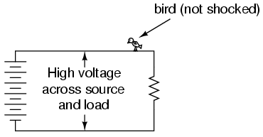
In order for electrons to flow through a conductor, there must be a voltage present to motivate them. Voltage, as you should recall, is always relative between two points. There is no such thing as voltage “on” or “at” a single point in the circuit, and so the bird contacting a single point in the above circuit has no voltage applied across its body to establish a current through it. Yes, even though they rest on two feet, both feet are touching the same wire, making them electrically common. Electrically speaking, both of the bird’s feet touch the same point, hence there is no voltage between them to motivate current through the bird’s body.
This might lend one to believe that its impossible to be shocked by electricity by only touching a single wire. Like the birds, if we’re sure to touch only one wire at a time, we’ll be safe, right? Unfortunately, this is not correct. Unlike birds, people are usually standing on the ground when they contact a “live” wire. Many times, one side of a power system will be intentionally connected to earth ground, and so the person touching a single wire is actually making contact between two points in the circuit (the wire and earth ground):
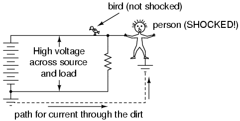
The ground symbol is that set of three horizontal bars of decreasing width located at the lower-left of the circuit shown, and also at the foot of the person being shocked. In real life the power system ground consists of some kind of metallic conductor buried deep in the ground for making maximum contact with the earth. That conductor is electrically connected to an appropriate connection point on the circuit with thick wire. The victim’s ground connection is through their feet, which are touching the earth.
A few questions usually arise at this point in the mind of the student:
- If the presence of a ground point in the circuit provides an easy point of contact for someone to get shocked, why have it in the circuit at all? Wouldn’t a ground-less circuit be safer?
- The person getting shocked probably isn’t bare-footed. If rubber and fabric are insulating materials, then why aren’t their shoes protecting them by preventing a circuit from forming?
- How good of a conductor can dirt be? If you can get shocked by current through the earth, why not use the earth as a conductor in our power circuits?
In answer to the first question, the presence of an intentional “grounding” point in an electric circuit is intended to ensure that one side of it is safe to come in contact with. Note that if our victim in the above diagram were to touch the bottom side of the resistor, nothing would happen even though their feet would still be contacting ground:
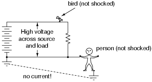
Because the bottom side of the circuit is firmly connected to ground through the grounding point on the lower-left of the circuit, the lower conductor of the circuit is made electrically common with earth ground. Since there can be no voltage between electrically common points, there will be no voltage applied across the person contacting the lower wire, and they will not receive a shock. For the same reason, the wire connecting the circuit to the grounding rod/plates is usually left bare (no insulation), so that any metal object it brushes up against will similarly be electrically common with the earth.
Circuit grounding ensures that at least one point in the circuit will be safe to touch. But what about leaving a circuit completely ungrounded? Wouldn’t that make any person touching just a single wire as safe as the bird sitting on just one? Ideally, yes. Practically, no. Observe what happens with no ground at all:
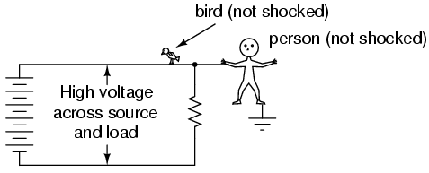
Despite the fact that the person’s feet are still contacting ground, any single point in the circuit should be safe to touch. Since there is no complete path (circuit) formed through the person’s body from the bottom side of the voltage source to the top, there is no way for a current to be established through the person. However, this could all change with an accidental ground, such as a tree branch touching a power line and providing connection to earth ground:
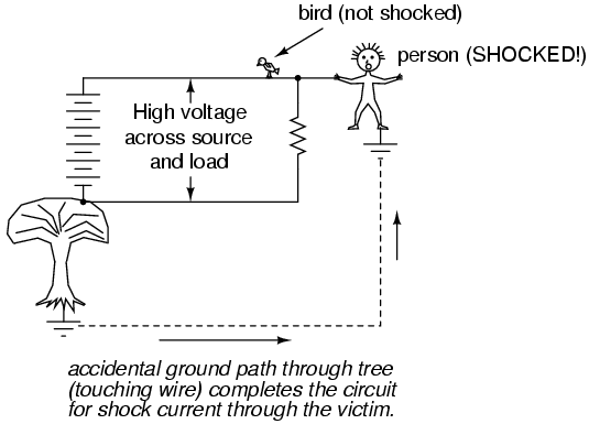
Such an accidental connection between a power system conductor and the earth (ground) is called a ground fault. Ground faults may be caused by many things, including dirt buildup on power line insulators (creating a dirty-water path for current from the conductor to the pole, and to the ground, when it rains), ground water infiltration in buried power line conductors, and birds landing on power lines, bridging the line to the pole with their wings. Given the many causes of ground faults, they tend to be unpredictable. In the case of trees, no one can guarantee which wire their branches might touch. If a tree were to brush up against the top wire in the circuit, it would make the top wire safe to touch and the bottom one dangerous—just the opposite of the previous scenario where the tree contacts the bottom wire:
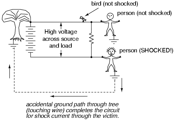
With a tree branch contacting the top wire, that wire becomes the grounded conductor in the circuit, electrically common with earth ground. Therefore, there is no voltage between that wire and ground, but full (high) voltage between the bottom wire and ground. As mentioned previously, tree branches are only one potential source of ground faults in a power system. Consider an ungrounded power system with no trees in contact, but this time with two people touching single wires:
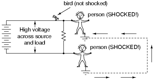
With each person standing on the ground, contacting different points in the circuit, a path for shock current is made through one person, through the earth, and through the other person. Even though each person thinks they’re safe in only touching a single point in the circuit, their combined actions create a deadly scenario. In effect, one person acts as the ground fault which makes it unsafe for the other person. This is exactly why ungrounded power systems are dangerous: the voltage between any point in the circuit and ground (earth) is unpredictable, because a ground fault could appear at any point in the circuit at any time. The only character guaranteed to be safe in these scenarios is the bird, who has no connection to earth ground at all! By firmly connecting a designated point in the circuit to earth ground (“grounding” the circuit), at least safety can be assured at that one point. This is more assurance of safety than having no ground connection at all.
In answer to the second question, rubber-soled shoes do indeed provide some electrical insulation to help protect someone from conducting shock current through their feet. However, most common shoe designs are not intended to be electrically “safe,” their soles being too thin and not of the right substance. Also, any moisture, dirt, or conductive salts from body sweat on the surface of or permeated through the soles of shoes will compromise what little insulating value the shoe had to begin with. There are shoes specifically made for dangerous electrical work, as well as thick rubber mats made to stand on while working on live circuits, but these special pieces of gear must be in absolutely clean, dry condition in order to be effective. Suffice it to say, normal footwear is not enough to guarantee protection against electric shock from a power system.
Research conducted on contact resistance between parts of the human body and points of contact (such as the ground) shows a wide range of figures (see end of chapter for information on the source of this data):
- Hand or foot contact, insulated with rubber: 20 MΩ typical.
- Foot contact through leather shoe sole (dry): 100 kΩ to 500 kΩ
- Foot contact through leather shoe sole (wet): 5 kΩ to 20 kΩ
As you can see, not only is rubber a far better insulating material than leather, but the presence of water in a porous substance such as leather greatly reduces electrical resistance.
In answer to the third question, dirt is not a very good conductor (at least not when its dry!). It is too poor of a conductor to support continuous current for powering a load. However, as we will see in the next section, it takes very little current to injure or kill a human being, so even the poor conductivity of dirt is enough to provide a path for deadly current when there is sufficient voltage available, as there usually is in power systems.
Some ground surfaces are better insulators than others. Asphalt, for instance, being oil-based, has a much greater resistance than most forms of dirt or rock. Concrete, on the other hand, tends to have fairly low resistance due to its intrinsic water and electrolyte (conductive chemical) content.
Safe Practices
If at all possible, shut off the power to a circuit before performing any work on it. You must secure all sources of harmful energy before a system may be considered safe to work on. In industry, securing a circuit, device, or system in this condition is commonly known as placing it in a Zero Energy State. The focus of this lesson is, of course, electrical safety. However, many of these principles apply to non-electrical systems as well.
Securing something in a Zero Energy State means ridding it of any sort of potential or stored energy, including but not limited to:
- Dangerous voltage
- Spring pressure
- Hydraulic (liquid) pressure
- Pneumatic (air) pressure
- Suspended weight
- Chemical energy (flammable or otherwise reactive substances)
- Nuclear energy (radioactive or fissile substances)
Voltage by its very nature is a manifestation of potential energy. In the first chapter I even used elevated liquid as an analogy for the potential energy of voltage, having the capacity (potential) to produce current (flow), but not necessarily realizing that potential until a suitable path for flow has been established, and resistance to flow is overcome. A pair of wires with high voltage between them do not look or sound dangerous even though they harbor enough potential energy between them to push deadly amounts of current through your body. Even though that voltage isn’t presently doing anything, it has the potential to, and that potential must be neutralized before it is safe to physically contact those wires.
All properly designed circuits have “disconnect” switch mechanisms for securing voltage from a circuit. Sometimes these “disconnects” serve a dual purpose of automatically opening under excessive current conditions, in which case we call them “circuit breakers.” Other times, the disconnecting switches are strictly manually-operated devices with no automatic function. In either case, they are there for your protection and must be used properly. Please note that the disconnect device should be separate from the regular switch used to turn the device on and off. It is a safety switch, to be used only for securing the system in a Zero Energy State:
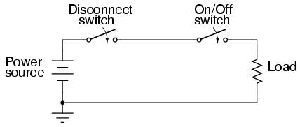
With the disconnect switch in the “open” position as shown (no continuity), the circuit is broken and no current will exist. There will be zero voltage across the load, and the full voltage of the source will be dropped across the open contacts of the disconnect switch. Note how there is no need for a disconnect switch in the lower conductor of the circuit. Because that side of the circuit is firmly connected to the earth (ground), it is electrically common with the earth and is best left that way. For maximum safety of personnel working on the load of this circuit, a temporary ground connection could be established on the top side of the load, to ensure that no voltage could ever be dropped across the load:
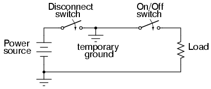
With the temporary ground connection in place, both sides of the load wiring are connected to ground, securing a Zero Energy State at the load.
Since a ground connection made on both sides of the load is electrically equivalent to short-circuiting across the load with a wire, that is another way of accomplishing the same goal of maximum safety:
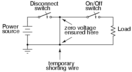
Either way, both sides of the load will be electrically common to the earth, allowing for no voltage (potential energy) between either side of the load and the ground people stand on. This technique of temporarily grounding conductors in a de-energized power system is very common in maintenance work performed on high voltage power distribution systems.
A further benefit of this precaution is protection against the possibility of the disconnect switch being closed (turned “on” so that circuit continuity is established) while people are still contacting the load. The temporary wire connected across the load would create a short-circuit when the disconnect switch was closed, immediately tripping any overcurrent protection devices (circuit breakers or fuses) in the circuit, which would shut the power off again. Damage may very well be sustained by the disconnect switch if this were to happen, but the workers at the load are kept safe.
It would be good to mention at this point that overcurrent devices are not intended to provide protection against electric shock. Rather, they exist solely to protect conductors from overheating due to excessive currents. The temporary shorting wires just described would indeed cause any overcurrent devices in the circuit to “trip” if the disconnect switch were to be closed, but realize that electric shock protection is not the intended function of those devices. Their primary function would merely be leveraged for the purpose of worker protection with the shorting wire in place.
Since it is obviously important to be able to secure any disconnecting devices in the open (off) position and make sure they stay that way while work is being done on the circuit, there is need for a structured safety system to be put into place. Such a system is commonly used in industry and it is called Lock-out/Tag-out.
A lock-out/tag-out procedure works like this: all individuals working on a secured circuit have their own personal padlock or combination lock which they set on the control lever of a disconnect device prior to working on the system. Additionally, they must fill out and sign a tag which they hang from their lock describing the nature and duration of the work they intend to perform on the system. If there are multiple sources of energy to be “locked out” (multiple disconnects, both electrical and mechanical energy sources to be secured, etc.), the worker must use as many of his or her locks as necessary to secure power from the system before work begins. This way, the system is maintained in a Zero Energy State until every last lock is removed from all the disconnect and shutoff devices, and that means every last worker gives consent by removing their own personal locks. If the decision is made to re-energize the system and one person’s lock(s) still remain in place after everyone present removes theirs, the tag(s) will show who that person is and what it is they’re doing.
Even with a good lock-out/tag-out safety program in place, there is still need for diligence and common-sense precaution. This is especially true in industrial settings where a multitude of people may be working on a device or system at once. Some of those people might not know about proper lock-out/tag-out procedure, or might know about it but are too complacent to follow it. Don’t assume that everyone has followed the safety rules!
After an electrical system has been locked out and tagged with your own personal lock, you must then double-check to see if the voltage really has been secured in a zero state. One way to check is to see if the machine (or whatever it is that’s being worked on) will start up if the Start switch or button is actuated. If it starts, then you know you haven’t successfully secured the electrical power from it.
Additionally, you should always check for the presence of dangerous voltage with a measuring device before actually touching any conductors in the circuit. To be safest, you should follow this procedure of checking, using, and then checking your meter:
- Check to see that your meter indicates properly on a known source of voltage.
- Use your meter to test the locked-out circuit for any dangerous voltage.
- Check your meter once more on a known source of voltage to see that it still indicates as it should.
While this may seem excessive or even paranoid, it is a proven technique for preventing electrical shock. I once had a meter fail to indicate voltage when it should have while checking a circuit to see if it was “dead.” Had I not used other means to check for the presence of voltage, I might not be alive today to write this. There’s always the chance that your voltage meter will be defective just when you need it to check for a dangerous condition. Following these steps will help ensure that you’re never misled into a deadly situation by a broken meter.
Finally, the electrical worker will arrive at a point in the safety check procedure where it is deemed safe to actually touch the conductor(s). Bear in mind that after all of the precautionary steps have taken, it is still possible (although very unlikely) that a dangerous voltage may be present. One final precautionary measure to take at this point is to make momentary contact with the conductor(s) with the back of the hand before grasping it or a metal tool in contact with it. Why? If, for some reason there is still voltage present between that conductor and earth ground, finger motion from the shock reaction (clenching into a fist) will break contact with the conductor. Please note that this is absolutely the last step that any electrical worker should ever take before beginning work on a power system, and should never be used as an alternative method of checking for dangerous voltage. If you ever have reason to doubt the trustworthiness of your meter, use another meter to obtain a “second opinion.”


