
1.5: Dimensioning
- Page ID
- 5186

\( \newcommand{\vecs}[1]{\overset { \scriptstyle \rightharpoonup} {\mathbf{#1}} } \)
\( \newcommand{\vecd}[1]{\overset{-\!-\!\rightharpoonup}{\vphantom{a}\smash {#1}}} \)
\( \newcommand{\dsum}{\displaystyle\sum\limits} \)
\( \newcommand{\dint}{\displaystyle\int\limits} \)
\( \newcommand{\dlim}{\displaystyle\lim\limits} \)
\( \newcommand{\id}{\mathrm{id}}\) \( \newcommand{\Span}{\mathrm{span}}\)
( \newcommand{\kernel}{\mathrm{null}\,}\) \( \newcommand{\range}{\mathrm{range}\,}\)
\( \newcommand{\RealPart}{\mathrm{Re}}\) \( \newcommand{\ImaginaryPart}{\mathrm{Im}}\)
\( \newcommand{\Argument}{\mathrm{Arg}}\) \( \newcommand{\norm}[1]{\| #1 \|}\)
\( \newcommand{\inner}[2]{\langle #1, #2 \rangle}\)
\( \newcommand{\Span}{\mathrm{span}}\)
\( \newcommand{\id}{\mathrm{id}}\)
\( \newcommand{\Span}{\mathrm{span}}\)
\( \newcommand{\kernel}{\mathrm{null}\,}\)
\( \newcommand{\range}{\mathrm{range}\,}\)
\( \newcommand{\RealPart}{\mathrm{Re}}\)
\( \newcommand{\ImaginaryPart}{\mathrm{Im}}\)
\( \newcommand{\Argument}{\mathrm{Arg}}\)
\( \newcommand{\norm}[1]{\| #1 \|}\)
\( \newcommand{\inner}[2]{\langle #1, #2 \rangle}\)
\( \newcommand{\Span}{\mathrm{span}}\) \( \newcommand{\AA}{\unicode[.8,0]{x212B}}\)
\( \newcommand{\vectorA}[1]{\vec{#1}} % arrow\)
\( \newcommand{\vectorAt}[1]{\vec{\text{#1}}} % arrow\)
\( \newcommand{\vectorB}[1]{\overset { \scriptstyle \rightharpoonup} {\mathbf{#1}} } \)
\( \newcommand{\vectorC}[1]{\textbf{#1}} \)
\( \newcommand{\vectorD}[1]{\overrightarrow{#1}} \)
\( \newcommand{\vectorDt}[1]{\overrightarrow{\text{#1}}} \)
\( \newcommand{\vectE}[1]{\overset{-\!-\!\rightharpoonup}{\vphantom{a}\smash{\mathbf {#1}}}} \)
\( \newcommand{\vecs}[1]{\overset { \scriptstyle \rightharpoonup} {\mathbf{#1}} } \)
\(\newcommand{\longvect}{\overrightarrow}\)
\( \newcommand{\vecd}[1]{\overset{-\!-\!\rightharpoonup}{\vphantom{a}\smash {#1}}} \)
\(\newcommand{\avec}{\mathbf a}\) \(\newcommand{\bvec}{\mathbf b}\) \(\newcommand{\cvec}{\mathbf c}\) \(\newcommand{\dvec}{\mathbf d}\) \(\newcommand{\dtil}{\widetilde{\mathbf d}}\) \(\newcommand{\evec}{\mathbf e}\) \(\newcommand{\fvec}{\mathbf f}\) \(\newcommand{\nvec}{\mathbf n}\) \(\newcommand{\pvec}{\mathbf p}\) \(\newcommand{\qvec}{\mathbf q}\) \(\newcommand{\svec}{\mathbf s}\) \(\newcommand{\tvec}{\mathbf t}\) \(\newcommand{\uvec}{\mathbf u}\) \(\newcommand{\vvec}{\mathbf v}\) \(\newcommand{\wvec}{\mathbf w}\) \(\newcommand{\xvec}{\mathbf x}\) \(\newcommand{\yvec}{\mathbf y}\) \(\newcommand{\zvec}{\mathbf z}\) \(\newcommand{\rvec}{\mathbf r}\) \(\newcommand{\mvec}{\mathbf m}\) \(\newcommand{\zerovec}{\mathbf 0}\) \(\newcommand{\onevec}{\mathbf 1}\) \(\newcommand{\real}{\mathbb R}\) \(\newcommand{\twovec}[2]{\left[\begin{array}{r}#1 \\ #2 \end{array}\right]}\) \(\newcommand{\ctwovec}[2]{\left[\begin{array}{c}#1 \\ #2 \end{array}\right]}\) \(\newcommand{\threevec}[3]{\left[\begin{array}{r}#1 \\ #2 \\ #3 \end{array}\right]}\) \(\newcommand{\cthreevec}[3]{\left[\begin{array}{c}#1 \\ #2 \\ #3 \end{array}\right]}\) \(\newcommand{\fourvec}[4]{\left[\begin{array}{r}#1 \\ #2 \\ #3 \\ #4 \end{array}\right]}\) \(\newcommand{\cfourvec}[4]{\left[\begin{array}{c}#1 \\ #2 \\ #3 \\ #4 \end{array}\right]}\) \(\newcommand{\fivevec}[5]{\left[\begin{array}{r}#1 \\ #2 \\ #3 \\ #4 \\ #5 \\ \end{array}\right]}\) \(\newcommand{\cfivevec}[5]{\left[\begin{array}{c}#1 \\ #2 \\ #3 \\ #4 \\ #5 \\ \end{array}\right]}\) \(\newcommand{\mattwo}[4]{\left[\begin{array}{rr}#1 \amp #2 \\ #3 \amp #4 \\ \end{array}\right]}\) \(\newcommand{\laspan}[1]{\text{Span}\{#1\}}\) \(\newcommand{\bcal}{\cal B}\) \(\newcommand{\ccal}{\cal C}\) \(\newcommand{\scal}{\cal S}\) \(\newcommand{\wcal}{\cal W}\) \(\newcommand{\ecal}{\cal E}\) \(\newcommand{\coords}[2]{\left\{#1\right\}_{#2}}\) \(\newcommand{\gray}[1]{\color{gray}{#1}}\) \(\newcommand{\lgray}[1]{\color{lightgray}{#1}}\) \(\newcommand{\rank}{\operatorname{rank}}\) \(\newcommand{\row}{\text{Row}}\) \(\newcommand{\col}{\text{Col}}\) \(\renewcommand{\row}{\text{Row}}\) \(\newcommand{\nul}{\text{Nul}}\) \(\newcommand{\var}{\text{Var}}\) \(\newcommand{\corr}{\text{corr}}\) \(\newcommand{\len}[1]{\left|#1\right|}\) \(\newcommand{\bbar}{\overline{\bvec}}\) \(\newcommand{\bhat}{\widehat{\bvec}}\) \(\newcommand{\bperp}{\bvec^\perp}\) \(\newcommand{\xhat}{\widehat{\xvec}}\) \(\newcommand{\vhat}{\widehat{\vvec}}\) \(\newcommand{\uhat}{\widehat{\uvec}}\) \(\newcommand{\what}{\widehat{\wvec}}\) \(\newcommand{\Sighat}{\widehat{\Sigma}}\) \(\newcommand{\lt}{<}\) \(\newcommand{\gt}{>}\) \(\newcommand{\amp}{&}\) \(\definecolor{fillinmathshade}{gray}{0.9}\)If a drawing is to be complete, so that the object represented by the drawing can be made as intended by the designer, it must tell two complete stories. It tells this with views, which describe the shape of the object, and with dimensions and notes, which gives sizes and other information needed to make the object.
Therefore, your next step is to learn the basics of dimensioning. In that way you will understand not only how to interpret a drawing to get the information you need, but also how to dimension your sketches so that they can be used to communicate size information to others.
Numerals
It may seem a bit basic, but a few exercises with the shapes of numbers comes before dimensioning. The reason for such review is simply that incorrectly or carelessly made numbers on a drawing or sketch can easily be misinterpreted by someone on the job. That can be costly.
Therefore, the study of numbers forms is justified.
The number forms presented here have been determined to be the most legible, and are used by industry nationwide. The United States standardized 1/8” vertical numbers are correctly formed as follows:
Dimension Lines
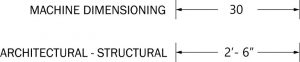
The dimension line is a fine, dark, solid line with arrowheads on each end. It indicates direction and extent of a dimension. In machine sketches and drawings, in which fractions and decimals are used for dimensions, the dimension line is usually broken near the middle to provide open space for the dimension numerals. In architectural and structural sketches and drawings, the numerals are usually above an unbroken dimension line.
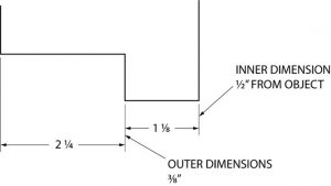
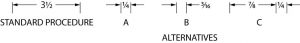
In either case, the dimension line which is closest to the object should be placed approximately
1/2″ away. The other dimensions beyond the first dimension (if any) should be approximately 3/8″ apart. You do not necessarily have to remember this, but you should remember not to crowd your dimension lines and to keep them a uniform distance apart.
The most important thing is that the drawing needs to be “clean” and dimensions need to be located in a space where they cannot be confused with a surface they are not intended to be used for.
Here is how dimension lines should be sketched:
Note: Dimensions less than six feet (72 in.) are given in inches. Dimensions over six feet are usually shown in feet and inches. Be sure that it is clear how dimensions are called out. When calling out dimensions that are over 12”, make sure ALL of dimensions are called out in total inches or feet inches throughout the entire drawing. Either 4’-5” or 53”, they both mean the same thing but if there is a mix of dimensioning it can become easy to look at 4’-8” and see 48”.
Extension Lines
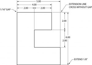
Extension lines on a drawing are fine, dark, solid lines that extend outward from a point on a drawing to which a dimension refers. Usually, the dimension line meets the extension line at right angles. There should be a gap of about 1 / 16″ where the extension line would meet the outline of the object, and the extension line should go beyond the outermost arrowhead approximately 1 /8″. Also, there should be not gaps where extension lines cross. Notice in this example the larger dimensions are correctly placed outside, or beyond the shorter dimensions, and that the dimensions are preferably not drawn on the object itself. Sometimes, however, it is necessary to dimension on the object.
It is important to remember to place dimensions on the views, in a two or three view drawing, where they will be the most easily understood. Avoid dimensioning to a hidden line and avoid the duplication of dimensions. Use common sense; keep dimensions as clear and simple as possible. Remember, the person reading your drawing needs to clearly understand, beyond question, how to proceed. Otherwise, costly time and material will be wasted.
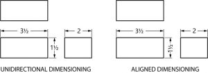
There are two basic methods of placing dimensions on a sketch. They may be placed so they read from the bottom of the sketch (unidirectional dimensions) or from the bottom and right side (aligned dimensions). The unidirectional system is usually best, because it is more easily read by workmen.
When dimensions will not fit in a space in the usual way, other methods are used to dimension clearly, when those crowded conditions exist.
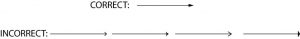
Arrowheads
Arrowheads are placed at each end of dimension lines, on leader lines, etc. Correctly made, arrows are about 1/8” to 3/16” in length, and are about three times as long as they are wide. Usually they have a slight barb, much like a fishhook.
To make your drawing look clean, use the same style throughout your drawing or sketch.
Dimension numerals
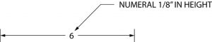
Numerals used to dimension an object are normally about 1/8” in height.
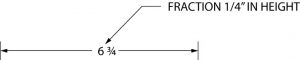
When a dimension includes a fraction, the fraction is approximately 1 / 4″ in height, making the fractional numbers slightly smaller to allow for space above and below the fractional line.
Again, it is particularly important that the numbers and fractions you may put on a sketch or drawing be legible. Sloppy numbers can cause expensive mistakes.
Notes
Notes are used on drawings to provide supplementary information. They should be brief and carefully worded to avoid being misinterpreted, and located on the sketch in an uncrowded area. The leader lines going to the note should be kept short. Notes are usually added after a sketch has been dimensioned to avoid interference with dimensions.
Quiz
Directions: Dimension the examples as indicated.
Dimension this 3 ¼ x 6 15/32 rectangle unidirectionally on the top and right sides.

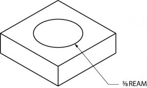
With a note, show a 5/16 drilled hole.
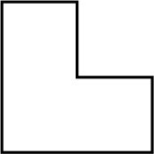
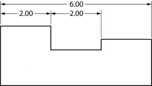
Dimension this object. The shorter lines are 3 inches in length.
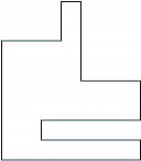
Dimension this object. Use a ruler or scale to determine the line lengths.
Oblique Dimensioning
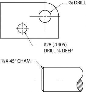
Oblique dimensioning is mostly remembering to avoid dimensioning on the object itself (when possible) and the use of common sense dimensioning principles. It is also usually best to have dimensions read from the bottom (unidirectional) as shown here.
Although it is best not to dimension on the view itself, its usually accepted practice to place diameter and radius dimension on the views if space permits.
Sometime space and time is limited and you might have to bend the typical rules of drawing and dimensioning. The most important thing is to keep the drawing clean, concise, try to not a repeat dimensions but give all required ones.
Directions: Complete as indicated.
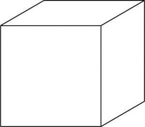
Dimension this three inch cube.
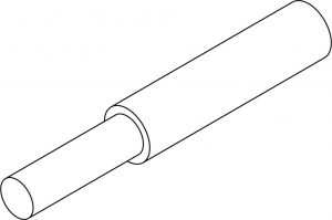
The shorter section of this rod is 5/8 inches in diameter by 2 1/8 inches long. The longer section is 7/8 inches in diameter by 3 ½ inches long. Dimension the drawing.
Isometric Dimensioning
When dimensioning an isometric sketch, it is important to keep dimensions away from the object itself, and to place the dimension on the same plane as the surface of the object being dimensioned. You will probably find that to dimension well in isometric will take some practice.
Place notes on an isometric drawing without regard to placing them on the same plane, as with dimensions. It is easier to do, and easier to read.
Isometric notes do not have to be on the same plane.
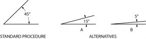
Notice in the example above that part of each leader line to the notes are sketched at an approximate angle of 15, 30, 45, 60 or 75 degrees. This is done to avoid confusion with other lines. Never draw leader lines entirely horizontal or vertical.
Quiz
Directions: complete as indicated.
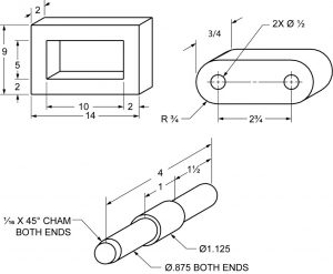
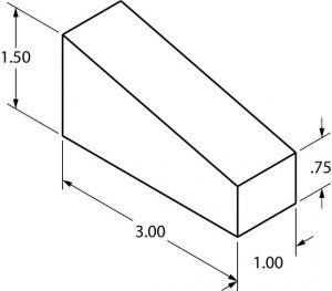
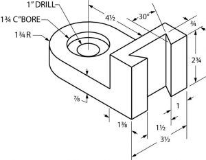
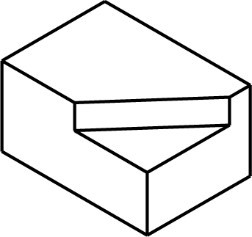
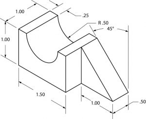
Dimension this drawing. The dimensions are 3” long, 2 1/8” wide, 1 5/8” high with a 45◦ angle ½” deep. The angle begins as the midpoint of the 3” long dimension.
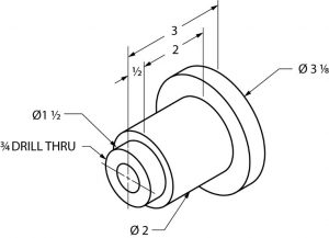
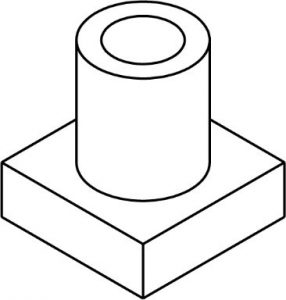
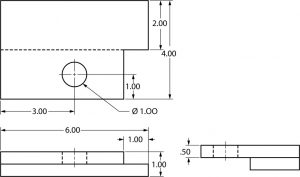
Dimension this drawing. The base is ½” x 1 ½” square. The cylinder is 1” ∅. x 1-1/8”
long. The drilled through hole is ∅5/8”.
Quiz
Directions: You will be given an object to sketch and dimension.
Orthographic Dimensioning
When you look at the dovetailed object several pages back, it is easy to see that an isometric sketch can quickly become cluttered with dimensions. Because of this, more complicated sketches and drawings are dimensional in orthographic. This method provides the best way to dimension clearly and in detail.
Here are seven general rules to follow when dimensioning.
- Show enough dimensions so that the intended sizes can be determined without having a workman calculate or assume any distances.
- State each dimension clearly, so it is understood in only one way.
- Show dimensions between points, lines or surfaces which have a necessary relationship to each other or which control the location of other components or mating parts.
- Select or arrange dimensions to avoid accumulations of dimensions that may cause unsatisfactory mating of parts. (In other words, provide for a buildup of tolerances, as in the example below.
- Show each dimension only once. (Do not duplicate dimensions).
- Where possible, dimension each feature in the view where it appears most clearly, and where its true shape appears.
- Whenever possible, specify dimensions to make use of readily available materials, parts and tools.
Notice the dimensions are correctly placed between the views, rather than around the outside edges of the drawing.
Quiz
Directions: one a separate piece of paper, make a dimensioned orthographic sketch of this object.
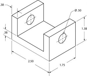
Directions: on a separate piece of paper, make a dimensional orthographic sketch of the object.
Quiz
Directions: You will be given an object to sketch and dimension.