8.4: Unit 4: CNC Language and Structure
- Page ID
- 2288
\( \newcommand{\vecs}[1]{\overset { \scriptstyle \rightharpoonup} {\mathbf{#1}} } \)
\( \newcommand{\vecd}[1]{\overset{-\!-\!\rightharpoonup}{\vphantom{a}\smash {#1}}} \)
\( \newcommand{\id}{\mathrm{id}}\) \( \newcommand{\Span}{\mathrm{span}}\)
( \newcommand{\kernel}{\mathrm{null}\,}\) \( \newcommand{\range}{\mathrm{range}\,}\)
\( \newcommand{\RealPart}{\mathrm{Re}}\) \( \newcommand{\ImaginaryPart}{\mathrm{Im}}\)
\( \newcommand{\Argument}{\mathrm{Arg}}\) \( \newcommand{\norm}[1]{\| #1 \|}\)
\( \newcommand{\inner}[2]{\langle #1, #2 \rangle}\)
\( \newcommand{\Span}{\mathrm{span}}\)
\( \newcommand{\id}{\mathrm{id}}\)
\( \newcommand{\Span}{\mathrm{span}}\)
\( \newcommand{\kernel}{\mathrm{null}\,}\)
\( \newcommand{\range}{\mathrm{range}\,}\)
\( \newcommand{\RealPart}{\mathrm{Re}}\)
\( \newcommand{\ImaginaryPart}{\mathrm{Im}}\)
\( \newcommand{\Argument}{\mathrm{Arg}}\)
\( \newcommand{\norm}[1]{\| #1 \|}\)
\( \newcommand{\inner}[2]{\langle #1, #2 \rangle}\)
\( \newcommand{\Span}{\mathrm{span}}\) \( \newcommand{\AA}{\unicode[.8,0]{x212B}}\)
\( \newcommand{\vectorA}[1]{\vec{#1}} % arrow\)
\( \newcommand{\vectorAt}[1]{\vec{\text{#1}}} % arrow\)
\( \newcommand{\vectorB}[1]{\overset { \scriptstyle \rightharpoonup} {\mathbf{#1}} } \)
\( \newcommand{\vectorC}[1]{\textbf{#1}} \)
\( \newcommand{\vectorD}[1]{\overrightarrow{#1}} \)
\( \newcommand{\vectorDt}[1]{\overrightarrow{\text{#1}}} \)
\( \newcommand{\vectE}[1]{\overset{-\!-\!\rightharpoonup}{\vphantom{a}\smash{\mathbf {#1}}}} \)
\( \newcommand{\vecs}[1]{\overset { \scriptstyle \rightharpoonup} {\mathbf{#1}} } \)
\( \newcommand{\vecd}[1]{\overset{-\!-\!\rightharpoonup}{\vphantom{a}\smash {#1}}} \)
\(\newcommand{\avec}{\mathbf a}\) \(\newcommand{\bvec}{\mathbf b}\) \(\newcommand{\cvec}{\mathbf c}\) \(\newcommand{\dvec}{\mathbf d}\) \(\newcommand{\dtil}{\widetilde{\mathbf d}}\) \(\newcommand{\evec}{\mathbf e}\) \(\newcommand{\fvec}{\mathbf f}\) \(\newcommand{\nvec}{\mathbf n}\) \(\newcommand{\pvec}{\mathbf p}\) \(\newcommand{\qvec}{\mathbf q}\) \(\newcommand{\svec}{\mathbf s}\) \(\newcommand{\tvec}{\mathbf t}\) \(\newcommand{\uvec}{\mathbf u}\) \(\newcommand{\vvec}{\mathbf v}\) \(\newcommand{\wvec}{\mathbf w}\) \(\newcommand{\xvec}{\mathbf x}\) \(\newcommand{\yvec}{\mathbf y}\) \(\newcommand{\zvec}{\mathbf z}\) \(\newcommand{\rvec}{\mathbf r}\) \(\newcommand{\mvec}{\mathbf m}\) \(\newcommand{\zerovec}{\mathbf 0}\) \(\newcommand{\onevec}{\mathbf 1}\) \(\newcommand{\real}{\mathbb R}\) \(\newcommand{\twovec}[2]{\left[\begin{array}{r}#1 \\ #2 \end{array}\right]}\) \(\newcommand{\ctwovec}[2]{\left[\begin{array}{c}#1 \\ #2 \end{array}\right]}\) \(\newcommand{\threevec}[3]{\left[\begin{array}{r}#1 \\ #2 \\ #3 \end{array}\right]}\) \(\newcommand{\cthreevec}[3]{\left[\begin{array}{c}#1 \\ #2 \\ #3 \end{array}\right]}\) \(\newcommand{\fourvec}[4]{\left[\begin{array}{r}#1 \\ #2 \\ #3 \\ #4 \end{array}\right]}\) \(\newcommand{\cfourvec}[4]{\left[\begin{array}{c}#1 \\ #2 \\ #3 \\ #4 \end{array}\right]}\) \(\newcommand{\fivevec}[5]{\left[\begin{array}{r}#1 \\ #2 \\ #3 \\ #4 \\ #5 \\ \end{array}\right]}\) \(\newcommand{\cfivevec}[5]{\left[\begin{array}{c}#1 \\ #2 \\ #3 \\ #4 \\ #5 \\ \end{array}\right]}\) \(\newcommand{\mattwo}[4]{\left[\begin{array}{rr}#1 \amp #2 \\ #3 \amp #4 \\ \end{array}\right]}\) \(\newcommand{\laspan}[1]{\text{Span}\{#1\}}\) \(\newcommand{\bcal}{\cal B}\) \(\newcommand{\ccal}{\cal C}\) \(\newcommand{\scal}{\cal S}\) \(\newcommand{\wcal}{\cal W}\) \(\newcommand{\ecal}{\cal E}\) \(\newcommand{\coords}[2]{\left\{#1\right\}_{#2}}\) \(\newcommand{\gray}[1]{\color{gray}{#1}}\) \(\newcommand{\lgray}[1]{\color{lightgray}{#1}}\) \(\newcommand{\rank}{\operatorname{rank}}\) \(\newcommand{\row}{\text{Row}}\) \(\newcommand{\col}{\text{Col}}\) \(\renewcommand{\row}{\text{Row}}\) \(\newcommand{\nul}{\text{Nul}}\) \(\newcommand{\var}{\text{Var}}\) \(\newcommand{\corr}{\text{corr}}\) \(\newcommand{\len}[1]{\left|#1\right|}\) \(\newcommand{\bbar}{\overline{\bvec}}\) \(\newcommand{\bhat}{\widehat{\bvec}}\) \(\newcommand{\bperp}{\bvec^\perp}\) \(\newcommand{\xhat}{\widehat{\xvec}}\) \(\newcommand{\vhat}{\widehat{\vvec}}\) \(\newcommand{\uhat}{\widehat{\uvec}}\) \(\newcommand{\what}{\widehat{\wvec}}\) \(\newcommand{\Sighat}{\widehat{\Sigma}}\) \(\newcommand{\lt}{<}\) \(\newcommand{\gt}{>}\) \(\newcommand{\amp}{&}\) \(\definecolor{fillinmathshade}{gray}{0.9}\)OBJECTIVE
After completing this unit, you should be able to:
- Identify the programs list instructions.
- Understand the Program Format
- Describe Letter Address Commands codes
- Describe Special Character Code Definitions.
- Understand the G & M Codes.
CNC programs list instructions to be performed in the order they are written. They read like a book, left to right and top-down. Each sentence in a CNC program is written on a separate line, called a Block. Blocks are arranged in a specific sequence that promotes safety, predictability and readability, so it is important to adhere to a standard program structure.
The blocks are arranged in the following order:
- Program Start
- Load Tool
- Spindle On
- Coolant On
- Rapid to position above part
- Machining operation
- Coolant Off
- Spindle Off
- Move to safe position
- End program
The steps listed above represent the simplest type of CNC program, where only one tool is used and one operation performed. Programs that use multiple tools repeat steps two through nine for each.
Table 3 and Table 4 in section G & M Codes show the most common G and M codes that should be memorized if possible.
Like any language, the G-code language has rules. For example, some codes are modal, meaning they do not have to be repeated if they do not change between blocks. Some codes have different meanings depending on how and where there are used.
While these rules are covered in this chapter, do not concern yourself with learning every nuance of the language. It is the job of the job of the CAD/CAM software Post Processor to properly format and write the CNC program.
Program Format
The program in Table 1: below machines a square contour and drills a hole.
Block | Description | Purpose |
% O1234 (T1 0.25 END MILL) G17 G20 G40 G49 G80 G90 | Start of program. Program number (Program Name). Tool description for operator. Safety block to ensure machine is in safe mode. | Start Program |
T1 M6 S9200 M3 | Load Tool #1. Spindle Speed 9200 RPM, On CW. | Change Tool |
G54 M8 G00 X-0.025 Y-0.275 G43 Z1.H1 Z0.1 G01 Z-0.1 F18. | Use Fixture Offset #1. Coolant On. Rapid above part. Rapid to safe plane, use Tool Length Offset #1. Rapid to feed plane. Line move to cutting depth at 18 IPM. | Move to Position |
G41 Y0.1 D1 F36. Y2.025 X2.025 Y-0.025 X-0.025 G40 X-0.4 G00 Z1. | CDC Left, Lead in line, Dia. Offset #1, 36 IPM. Line move. Line move. Line move. Line move. Turn CDC off with lead-out move. Rapid to safe plane. | Machine Contour |
M5 M9 (T2 0.25 DRILL) T2 M6 S3820 M3 | Spindle Off. Coolant Off. Tool description for operator. Load Tool #2. Spindle Speed 3820 RPM, On CW. | Change Tool |
M8 X1. Y1. G43 Z1.H2 Z0.25 | Coolant On. Rapid above hole. Rapid to safe plane, use Tool Length Offset 2. Rapid to feed plane. | Move to Position |
G98 G81 Z-0.325 R0.1 F12. G80 Z1. | Drill hole (canned) cycle, Depth Z-.325, F12. Cancel drill cycle. Rapid to safe plane. | Drill Hole |
M5 M9 G91 G28 Z0 G91 G28 X0 Y0 G90 M30 % | Spindle Off. Coolant Off. Return to machine Home position in Z. Return to machine Home position in XY. Reset to absolute positioning mode (for safety). Reset program to beginning. End Program. | End Program |
Letter Address Commands codes
The command block controls the machine tool through the use of letter address commands. Some are used more than once, and their meaning changes based on which G-code appears in the same block.
Codes are either modal, which means they remain in effect until cancelled or changed, or non-modal, which means they are effective only in the current block. As you can see, many of the letter addresses are chosen in a logical manner (T for tool, S for spindle, F for feed rate, etc.).
The table below lists the most common Letter Address Commands codes.
Table 2: Letter Address Commands Codes
Variable | Description | Definitions |
A | Absolute or incremental position ofAaxis (rotational axis around X axis) | A,B,C – 4th/5th Axis Rotary Motion Rotation about the X, Y or Z-axis respectively.The angle is in degrees and up to three decimal places precision. |
B | Absolute or incremental position of B axis (rotational axis around Y axis) | Same as A |
C | Absolute or incremental position of C axis (rotational axis around Z axis) | Same as B |
D | Defines diameter or radial offset used for cutter compensation | Used to compensate for tool diameter wear and deflection.D is accompanied by an integer that isthe same as the tool number (T5 uses D5,etc). No decimal point is used. Itis always usedin conjunction with G41 or G42 and a XY move (never an arc). When called, the control reads the register and offsets the tool path left (G41) or right (G42) by the value in the register. |
E | Precision feed rate for threading on lathes | |
F | Defines feed rate | Sets the feed rate when machining lines, arcs or drill cycles.Feed rate can be in Inches per Minute (G94 mode) or Inverse Time (G93 mode). Feed rates can be up to three decimal placesaccuracy (for tap cycles) and require a decimal point. |
G | Address for preparatory commands | G commands often tell the control what kind of motion is wanted (e.g., rapid positioning, linear feed, circular feed, fixed cycle) or what offset value to use. G02 X2.Y2.I.50J0. |
H | Defines tool length offset; Incremental axis corresponding to C axis (e.g., on a turn-mill) | This code calls a tool length offset (TLO) register on the control. The control combines the TLO and Fixture Offset Z values to know where the tool is in relation to the part datum.It is always accompanied by an integer (H1, H2,etc), G43, and Z coordinate. |
I | Defines arc size inX axisfor G02 or G03 arc commands. Also used as a parameter within some fixed cycles. | For arc moves (G2/G3), this is the incremental X-distance from the arc start point to the arc center. Certain drill cycles also use I as an optional parameter. |
J | Defines arc size inY axisfor G02 or G03 arc commands. Also used as a parameter within some fixed cycles. | For arc moves (G2/G3), this is the incremental Y-distance from the arc start point to the arc center. Certain drill cycles also use J as an optional parameter. |
K | Defines arc size inZ axisfor G02 or G03 arc commands. Also used as a parameter within some fixed cycles, equal to L address. | For anarcmove (G2/G3) this is the incremental Z-distance from the arc start point to the arc center. In the G17 plane, this is the incremental Z-distance for helical moves. Certain drill cycles also use J as an optional parameter. |
L | Fixed cycle loop count; Specification of what register to edit using G10 | Fixed cycle loop count: Defines number of repetitions (“loops”) of a fixed cycle at each position.Assumed to be 1 unless programmed with another integer.Sometimes the K addressis usedinstead of L. With incremental positioning (G91), a series of equally spaced holes can be programmed as a loop rather than as individual positions.G10 use:Specificationof what register to edit (work offsets, tool radius offsets, tool length offsets, etc.). |
M | Miscellaneous function | Always accompanied by an integer that determines its meaning.Only one M-codeis allowedin each block of code. Expanded definitions of M-codes appear later in this chapter. |
N | Line (block) number in program; System parameter number to be changed using G10 | Block numbers can make the CNC program easier to read. They are seldom required for CAD/CAM generated programs with no subprograms. Because they take up controlmemorymost 3D programs do not use block numbers. Block numbers are integers up to five characters long with no decimal point. They cannot appear before the tape start/end character (%) and usually do not appear before a comment only block. |
O | Program name | Programs are stored on the control by their program number. Thisis an integer thatis preceded by the letter O and has no decimal places. |
P | Serves as parameter address for various G and M codes | Dwell (delay) in seconds.Accompanied by G4 unless used within certain drill cycles. |
Q | Peck increment in canned cycles | The incremental feed distance per pass in a peck drill cycle. |
R | Defines size of arc radius or defines retract height in canned cycles | Arcs can be defined using the arc radius R or I,J,Kvectors. IJK’s are more reliable than R’s so itis recommendedto use them instead. Ris also usedby drill cycles as the return plane Z value. |
S | Defines speed, either spindle speed or surface speed depending on mode | Spindle speed in revolutions per minute (RPM). It is an integer value with no decimal, and always used in conjunction with M03 (Spindle on CW) or M04 (Spindle on CCW). |
T | Tool selection | Selects tool. It is an integer value always accompanied by M6 (tool change code). |
U | Incremental axis corresponding to X axis (typically only lathe group A controls) Also defines dwell time on some machines. | In these controls, X and U obviate G90 and G91, respectively. On these lathes, G90 is instead a fixed cycle address for roughing. |
V | Incremental axis corresponding to Y axis | Until the 2000s, the V address was very rarely used, because most lathes that used U andWdidn’thave a Y-axis, so they didn’t use V. (Green et al 1996 did not even list V in their table of addresses.) That is still often the case, although the proliferation of live lathe tooling and turn-mill machining has made V address usage less rare than it used to be (Smid2008 shows an example). |
W | Incremental axis corresponding to Z axis (typically only lathe group A controls) | In these controls, Z and W obviate G90 and G91, respectively. On these lathes, G90 is instead a fixed cycle address for roughing. |
X | Absolute or incremental position ofX axis. | Coordinate data for the X-axis. Up to four places after the decimalare allowedand trailing zeros are not used. Coordinates are modal, so there is no need to repeat them in subsequent blocks if they do not change. |
Y | Absolute or incremental position of Y axis | Coordinate data for the Y-axis. G01 Y2.250 F20. |
Z | Absolute or incremental position of Z axis | Coordinate data for the Z-axis. |
Special Character Code Definitions
The following is a list of commonly used special characters, their meaning, use, and restrictions.
% – Program Start or End
All programs begin and end with % on a block by itself. This code is called tape rewind character (a holdover from the days when programs were loaded using paper tapes).
( ) – Comments
Comments to the operator must be all caps and enclosed within brackets. The maximum length of a comment is 40 characters and all characters are capitalized.
(T02: 5/8 END MILL)
/ – Block Delete
Codes after this character are ignored if the Block Delete switch on the control is on.
/ M00
; – End of Block
This character is not visible when the CNC program is read in a text editor (carriage return), but does appear at the end of every block of code when the program is displayed on the machine control.
N8 Z0.750 ;
G & M Codes
G&M Codes make up the most of the contents of the CNC program. The definition of each class of code and specific meanings of the most important codes are covered next.
G-Codes
Codes that begin with G are called preparatory words because they prepare the machine for a certain type of motion.
Table 3: G-Code
Code | Description |
G00 | Rapid motion.Used to position the machine for non-milling moves. |
G01 | Line motion at a specified feed rate. |
G02 | Clockwise arc. |
G03 | Counterclockwise arc. |
G04 | Dwell. |
G28 | Return to machine home position. |
G40 | Cutter Diameter Compensation (CDC) off. |
G41 | Cutter Diameter Compensation (CDC) left. |
G42 | Cutter Diameter Compensation (CDC) right. |
G43 | Tool length offset (TLO). |
G54 | Fixture Offset #1. |
G55 | Fixture Offset #2. |
G56 | Fixture Offset #3. |
G57 | Fixture Offset #4. |
G58 | Fixture Offset #5. |
G59 | Fixture Offset #6. |
G80 | Cancel drill cycle. |
G81 | Simple drill cycle. |
G82 | Simple drill cycle with dwell. |
G83 | Peck drill cycle. |
G84 | Tap cycle. |
G90 | Absolute coordinate programming mode. |
G91 | Incremental coordinate programming mode. |
G98 | Drill cycle return to Initial point (R). |
G99 | Drill cycle return to Reference plane (last Z Height) |
M-Codes
Codes that begin with M are called miscellaneous words. They control machine auxiliary options like coolant and spindle direction. Only one M-code can appear in each block of code.
Table 4: M-Codes
Code | Description |
M00 | Program stop.Press Cycle Start button to continue. |
M01 | Optional stop. |
M02 | End of program. |
M03 | Spindle on Clockwise. |
M04 | Spindle on Counterclockwise. |
M05 | Spindle stop. |
M06 | Change tool. |
M08 | Coolant on. |
M09 | Coolant off. |
M30 | End program and press Cycle Start to run it again. |
Select G-Code Definitions (Expanded)
G00 – Rapid Move
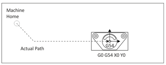
This code commands the machine to move as fast as it can to a specified point. It is always used with a coordinate position and is modal. Unlike G01, G00 does not coordinate the axes to move in a straight line. Rather, each axis moves at its maximum speed until it is satisfied. This results in motion as shown in Figure 18, below.
G 0 0 X 0 . Y0.