
1.6: Valves
- Page ID
- 6997

\( \newcommand{\vecs}[1]{\overset { \scriptstyle \rightharpoonup} {\mathbf{#1}} } \)
\( \newcommand{\vecd}[1]{\overset{-\!-\!\rightharpoonup}{\vphantom{a}\smash {#1}}} \)
\( \newcommand{\id}{\mathrm{id}}\) \( \newcommand{\Span}{\mathrm{span}}\)
( \newcommand{\kernel}{\mathrm{null}\,}\) \( \newcommand{\range}{\mathrm{range}\,}\)
\( \newcommand{\RealPart}{\mathrm{Re}}\) \( \newcommand{\ImaginaryPart}{\mathrm{Im}}\)
\( \newcommand{\Argument}{\mathrm{Arg}}\) \( \newcommand{\norm}[1]{\| #1 \|}\)
\( \newcommand{\inner}[2]{\langle #1, #2 \rangle}\)
\( \newcommand{\Span}{\mathrm{span}}\)
\( \newcommand{\id}{\mathrm{id}}\)
\( \newcommand{\Span}{\mathrm{span}}\)
\( \newcommand{\kernel}{\mathrm{null}\,}\)
\( \newcommand{\range}{\mathrm{range}\,}\)
\( \newcommand{\RealPart}{\mathrm{Re}}\)
\( \newcommand{\ImaginaryPart}{\mathrm{Im}}\)
\( \newcommand{\Argument}{\mathrm{Arg}}\)
\( \newcommand{\norm}[1]{\| #1 \|}\)
\( \newcommand{\inner}[2]{\langle #1, #2 \rangle}\)
\( \newcommand{\Span}{\mathrm{span}}\) \( \newcommand{\AA}{\unicode[.8,0]{x212B}}\)
\( \newcommand{\vectorA}[1]{\vec{#1}} % arrow\)
\( \newcommand{\vectorAt}[1]{\vec{\text{#1}}} % arrow\)
\( \newcommand{\vectorB}[1]{\overset { \scriptstyle \rightharpoonup} {\mathbf{#1}} } \)
\( \newcommand{\vectorC}[1]{\textbf{#1}} \)
\( \newcommand{\vectorD}[1]{\overrightarrow{#1}} \)
\( \newcommand{\vectorDt}[1]{\overrightarrow{\text{#1}}} \)
\( \newcommand{\vectE}[1]{\overset{-\!-\!\rightharpoonup}{\vphantom{a}\smash{\mathbf {#1}}}} \)
\( \newcommand{\vecs}[1]{\overset { \scriptstyle \rightharpoonup} {\mathbf{#1}} } \)
\( \newcommand{\vecd}[1]{\overset{-\!-\!\rightharpoonup}{\vphantom{a}\smash {#1}}} \)
\(\newcommand{\avec}{\mathbf a}\) \(\newcommand{\bvec}{\mathbf b}\) \(\newcommand{\cvec}{\mathbf c}\) \(\newcommand{\dvec}{\mathbf d}\) \(\newcommand{\dtil}{\widetilde{\mathbf d}}\) \(\newcommand{\evec}{\mathbf e}\) \(\newcommand{\fvec}{\mathbf f}\) \(\newcommand{\nvec}{\mathbf n}\) \(\newcommand{\pvec}{\mathbf p}\) \(\newcommand{\qvec}{\mathbf q}\) \(\newcommand{\svec}{\mathbf s}\) \(\newcommand{\tvec}{\mathbf t}\) \(\newcommand{\uvec}{\mathbf u}\) \(\newcommand{\vvec}{\mathbf v}\) \(\newcommand{\wvec}{\mathbf w}\) \(\newcommand{\xvec}{\mathbf x}\) \(\newcommand{\yvec}{\mathbf y}\) \(\newcommand{\zvec}{\mathbf z}\) \(\newcommand{\rvec}{\mathbf r}\) \(\newcommand{\mvec}{\mathbf m}\) \(\newcommand{\zerovec}{\mathbf 0}\) \(\newcommand{\onevec}{\mathbf 1}\) \(\newcommand{\real}{\mathbb R}\) \(\newcommand{\twovec}[2]{\left[\begin{array}{r}#1 \\ #2 \end{array}\right]}\) \(\newcommand{\ctwovec}[2]{\left[\begin{array}{c}#1 \\ #2 \end{array}\right]}\) \(\newcommand{\threevec}[3]{\left[\begin{array}{r}#1 \\ #2 \\ #3 \end{array}\right]}\) \(\newcommand{\cthreevec}[3]{\left[\begin{array}{c}#1 \\ #2 \\ #3 \end{array}\right]}\) \(\newcommand{\fourvec}[4]{\left[\begin{array}{r}#1 \\ #2 \\ #3 \\ #4 \end{array}\right]}\) \(\newcommand{\cfourvec}[4]{\left[\begin{array}{c}#1 \\ #2 \\ #3 \\ #4 \end{array}\right]}\) \(\newcommand{\fivevec}[5]{\left[\begin{array}{r}#1 \\ #2 \\ #3 \\ #4 \\ #5 \\ \end{array}\right]}\) \(\newcommand{\cfivevec}[5]{\left[\begin{array}{c}#1 \\ #2 \\ #3 \\ #4 \\ #5 \\ \end{array}\right]}\) \(\newcommand{\mattwo}[4]{\left[\begin{array}{rr}#1 \amp #2 \\ #3 \amp #4 \\ \end{array}\right]}\) \(\newcommand{\laspan}[1]{\text{Span}\{#1\}}\) \(\newcommand{\bcal}{\cal B}\) \(\newcommand{\ccal}{\cal C}\) \(\newcommand{\scal}{\cal S}\) \(\newcommand{\wcal}{\cal W}\) \(\newcommand{\ecal}{\cal E}\) \(\newcommand{\coords}[2]{\left\{#1\right\}_{#2}}\) \(\newcommand{\gray}[1]{\color{gray}{#1}}\) \(\newcommand{\lgray}[1]{\color{lightgray}{#1}}\) \(\newcommand{\rank}{\operatorname{rank}}\) \(\newcommand{\row}{\text{Row}}\) \(\newcommand{\col}{\text{Col}}\) \(\renewcommand{\row}{\text{Row}}\) \(\newcommand{\nul}{\text{Nul}}\) \(\newcommand{\var}{\text{Var}}\) \(\newcommand{\corr}{\text{corr}}\) \(\newcommand{\len}[1]{\left|#1\right|}\) \(\newcommand{\bbar}{\overline{\bvec}}\) \(\newcommand{\bhat}{\widehat{\bvec}}\) \(\newcommand{\bperp}{\bvec^\perp}\) \(\newcommand{\xhat}{\widehat{\xvec}}\) \(\newcommand{\vhat}{\widehat{\vvec}}\) \(\newcommand{\uhat}{\widehat{\uvec}}\) \(\newcommand{\what}{\widehat{\wvec}}\) \(\newcommand{\Sighat}{\widehat{\Sigma}}\) \(\newcommand{\lt}{<}\) \(\newcommand{\gt}{>}\) \(\newcommand{\amp}{&}\) \(\definecolor{fillinmathshade}{gray}{0.9}\)In this chapter, we will examine water distribution valves and why they are used.
Student Learning Outcomes
After reading this chapter, you should be able to:
- Describe the different types of valves
- Explain why different valves are used with different applications
- Identify the operational and maintenance criteria for valves
Water valves are an important part to any water system. The main purpose of a valve is to stop and isolate the flow of water. There are many different types of valves and the uses vary, but the primary purpose is to stop the flow of water. However, as you will see in this chapter, valves serve a variety of purposes.
Valves are used to stop and start the flow of water. When a pipe breaks, in order to stop the flow of water a valve is commonly closed. This prevents the water from flowing and allows for utility operators to repair the pipe. Once the repair is finished, the valve is opened and water is allowed to flow once again.
Some valves are used to regulate pressure or throttle flow. Sometimes the water pressure is too great and can pose a problem and damage pipes or other equipment. Residential homes commonly use pressure regulating valves in order to reduce the pressure before the water enters a home. These types of valves can also be used within a utilities distribution system. Throttling flow is sometimes needed in order to reduce the amount of water passing through pipes.
Certain valves are used to allow the flow of water in one direction only. These valves prevent the flow of water in the opposite direction. A common type of valve is a check or backflow preventer. These valves are unidirectional valves and allow the water to flow in one direction only.
Other valves are designed to relieve pressure. When water pressure builds up and gets to a point where the pipes or other appurtenances can get damage, a pressure relief valve can be used to allow the water to flow out of the system and relieve the high pressure.
Types of Valves
There are a number of different types of valves in the water industry for the various uses described above. The following list of valves is not an exhaustive list, but it is a very comprehensive list of valves used in the water industry:
- Gate
- Globe
- Pinch
- Diaphragm
- Needle
- Plug
- Ball
- Butterfly
- Check
- Relief
- Control
Each one of these valves has specific uses and some of these valves are more commonly used than others. Understanding the various uses and types of valves is important for understanding how water distribution systems function. For example, there are several types of valves commonly used in water mains in order to stop the flow of water. However, a certain type (butterfly) is not suitable for a maintenance function referred to as “pigging”.
Pigging is a process to clean the inside of a water main. “Pigs” are made from various materials, but are commonly made of foam of various densities and are pushed through a water main. If a water utility uses butterfly valves then this type of cleaning process is not possible because the valve would be an obstruction. Other types of valves can be used at pump stations, wells, or other locations within a water distribution system.
Each valve will be discussed in detail throughout this text. However, it is important to understand the four (4) principle uses of valves within a distribution system.
- Starting and Stopping Flow – In order to change the direction of the flow of water, stop the flow of water, and then start the flow of water, certain valves are used. When a water pipe breaks, a valve is used in order to stop the flow of water and isolate the leak so it can be repaired. Once the repair is made, the valve will be opened in order to start the flow of water once again. Some examples of these valves in a distribution system are distribution system isolation valves, fire hydrant auxiliary valves, pump control valves, and water service valves.
- Regulate Pressure and Throttle Flow – Certain valves are used to lower the pressure if it is too high or to reduce the flow of water by throttling the flow. Only specific valves should be used for these purposes because some valves can get damaged if used for the incorrect purpose. An example of a pressure regulating valves within a distribution system is one installed between two different pressure zones. One zone is higher than the other and these types of valves can be installed to reduce the higher pressure and release water when needed to the lower pressure area.
- Prevent Backflow – To prevent water from flowing in the wrong direction certain valves can be used to prevent something referred to as backflow. Backflow prevention is needed when a potable water supply is connected to a non-potable water supply. There are five (5) main methods and devices used for preventing backflow. These will be discussed later in this chapter.
- Relieve Pressure – When pressure is too high within a water system, sometimes the pressure needs to be relieved in order to prevent a rupture of the system. Pressure relief valves are common in various installations. Air and vacuum valves are an example of a pressure relief valve within a distribution system. These valves allow air to escape preventing sudden rupture of a pipe.
What Differentiates the Various Types of Valves?
Valves can be classified by how they regulate the flow of water. There are four (4) main types of how a valve operates:
- Closing Down – Globe and Piston valves close down in order to stop the flow of water
A globe valve is commonly found on outside residential faucets, also referred to as a sill cock. The “plug” end of a globe valve closes down into a valve port, which shuts off the flow of water. The distance between fully open and fully closed is relatively short.
A piston valve is similar to a globe valve. It is equipped with a piston shaped closure member, which intrudes into a seat bore to stop the flow of water. Piston valves are commonly used on control valves.
These types of valves are susceptible to sediment being trapped on the seat preventing the valve to close down completely. There is also some amount of flow resistance with these types of valves, especially a piston valve.
- Sliding – Gate valves are the most common valve found in distribution systems. They are classified as a sliding down style. A handwheel or a key lowers a “gate” down on a seat. The face of the gate can become worn or objects can get lodged under the gate preventing a tight or complete seal. These types of valves should not be used to throttle flows as the gate can become damaged from the force of the flow of water. There are several different types of gate valves and they will be discussed later in this chapter. The image below is an above-ground type of gate valve with a handwheel attached to the operating nut for opening and closing.
- Rotating – The various types of rotating valves include, plug, ball, butterfly, and cone. These types of valves rotate to open and close. Some, for example, plug and ball valves, are rotary style rotating valves. This means they are quarter or half turn rotary valves. While others like butterfly valves rotate on a shaft to open and close.
In the diagram above, the lever of a ball valve is turned one-quarter of the way and the ball that is blocking the flow opens to allow water to flow through. The “ball” that is in the line of flow is solid on each side and is open on the other sides. The rotating cylinder on these valves can also be cone-shaped. Smaller plug valves are used on customer service lines. The valve that connects a distribution main to a service lateral is called corporation stops (corp stop) and the valve that connects the service lateral to a meter is a curb stop. These are also referred to as meter and angle stops. They can be used to throttle flow without being damaged.
- Flexing – The last style of valve based on how it operates is a “flexing” valve. These valves are either diaphragm or pinch style valves. The flow is reduced or stopped by a squeezing or pinching effect to obstruct the flow. The material inside of these valves need to be flexible and are commonly resistant to corrosion.
Gate Valves
Gate valves are one of the most widely used valves in a water distribution system. As previously mentioned their primary function is to start and stop the flow of water. These types of valves should not be used for throttling the flow of water as they can become damaged. The gate (slide) is lowered and raised by a hand wheel in above-ground installations and a nut with a key on below-ground installations. The face of a gate valve can become worn, especially if they are throttled and objects can become lodged under the gate, which prevents a proper seal.
The gate picture above is the style used below the ground surface. The nut on top of the valve bonnet is operated with a “T” shaped key with a 2” square case that fits on top of the nut. The other gate valve pictured above is one used in above-ground installations and is operated with a handwheel. There are several different styles of gate valves, and they have various purposes. The list below identifies some of these valves:
- Non-rising stem (NRS) – The below ground gate valves are considered non-rising stem. These valves take up less space and have the screw mechanism protected.
- Rising stem – A rising stem gate valve is commonly used on fire systems. The reason is that it is easily detected if the valve is open or closed by the position of the stem. These types of valves are also called “outside stem and yoke” or OS&Y valves. The picture depicts this type of valve. When the stem is up, the valve is open.
- Horizontal – In shallow below ground installations, horizontal gate valves are commonly used. They allow for low clearance and they are also easier to operate. Instead of having to lift the gate up when operating, the gate slides to the side. So, in addition to installations when the ground cover is minimum, large valves can also be horizontal gate valves.
- Tapping, Cutting-In, Inserting – Several styles of gate valves are classified based on the use in construction practices. Tapping, cutting-in, and inserting valves are all used based on adding a valve in an existing distribution system. Tapping valves are used exclusively when a connection needs to be made to a water main. Hence, “tapping” into the water main. There are two types of taps, wet or hot tap and dry tap. A hot tap is done while the water main is in use and service cannot be disrupted. A dry tap is when the pipeline is shut down and the water is drained from the pipe.
The two other methods of adding a valve to an existing water system are cutting-in or inserting. A pipe can be cut and a valve is added or a valve can be inserted into the pipe. The picture below is an example of an insertion gate valve.
A cutting-in valve was one oversized end connection designed to be used with a cutting-in sleeve. The valve and sleeve are used together to facilitate installation of a new valve in an existing main. Pressure must be shut off for a short time. Inserting valves are installed when water cannot be shut off and the main cannot be depressurized.
- Resilient seated – Gate valves are commonly made of various types of metallic materials. However, rubber, urethane rubber, and other synthetic materials are also used to make the closure member. In addition, the seat is made from this same material, providing a tight and complete closing seal.
- Slide – Gate valves are sliding (sluice) valves, but a slide gate is a simple gate style valve. They are designed to release large volumes of water at one time and are often found in large agricultural systems. The gate or blade is relatively thin, they do not provide a completely tight shut off, and can be square, oblong, or round in shape.
One of the main advantages of gate valves is the ability to block or let flow happen in both directions. They also offer little to no resistance when fully open and allow a clear waterway for the flow of water. In addition to the various styles of gate valves, they are classified into three (3) main types: double-disc, solid wedge, and resilient seated (as previously discussed). A double-disc gate valve is made up of two relatively loose-fitting discs that, when closed, are pressed against metal seats by a wedging mechanism. Water pushes past the upstream disc and allows the area between the two discs to become pressurized when the discs are in a closed position. The pressure is then released when the valve is opened. Some of these valves are equipped with a bypass to equalize the pressure on both sides to make it easier to open. The main disadvantage is the large frictional on the downstream disc making it difficult to lift off the seat. A solid wedge gate valve involves a closure member that is a single wedge guided into fitted, tapered seats. Although throttling is not recommended with gate valves, the solid wedge is more desirable because of the close guiding between the wedge and the body. Resilient seated gate valves were previously discussed.
Other Valves
Plug valves are a type of rotary valve and can be used to throttle and control flow. Even when open, they cause some flow resistance. There are three (3) basic types of plug valves, lubricated, non-lubricated, and eccentric. With lubricated plug valves, grease is used to lubricate the plug motion and to seal the gap between the plug and the valve body. On a non-lubricated plug valve, the valve is mechanically lifted up from or pushed down to the seat. An eccentric plug valve is a non-lubricated valve that rotates the plug and pulls away from the seat. Another type of rotary valve is a cone valve. These are limited in use because of their size and weight, but they are good for controlling flow and provide low flow resistance. Ball valves require a 90-degree rotation between the open and closed position, have low flow resistance, and are also suitable for throttling flow.
Another common valve within the water industry is a butterfly valve. A butterfly valve is another valve that rotates. It has a disc similar to a gate valve, but this disc rotates on a shaft to open and close. Butterfly valves are easier to operate than a gate valve because as they open, the force of the water pushes against the opposite side of the disc helping to open the valve. The main disadvantage of a butterfly valve is that they have a high resistance to flow because the valve, even when fully open, is always in the flow path. The disc can also get damaged from the vibration of the flowing water. Since they have a short laying length (distance between each side of the flanges), they are used where space is limited. They are also lighter in weight and less expensive than gate valves.
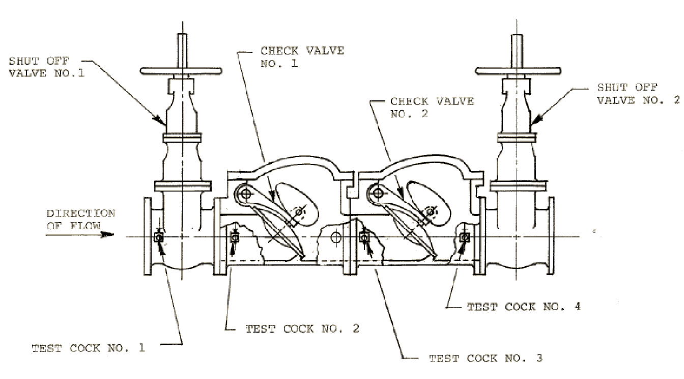
A check valve allows flow in only one direction and therefore has very specific applications. There are five (5) main types of check valves.
- Slanting disc – Provide the lowest head loss of any check valve and are commonly used in larger pipelines to save on pumping costs
- Cushioned swing – Results in a soft or cushioned closing of the valve when the flow of water stops
- Rubber swing – Instead of the valve swinging on a hinge pin, like most other check valves, a rubber swing flexes to open
- Double door – While all check valves are designed to allow flow in only one direction, a double door check valve is designed to have a greater seal when closed. These types of valve are more common in industrial operations.
- Foot – These are special types of check valves installed on groundwater wells in order to prevent water from flowing backwards out of a pump and well piping back into the well when the well pump stops operating. They are installed at the bottom of a pump suction line and are used to prime the pump.
Relieving and Controlling Pressure
Pressure relief valves are very common in installations where pressures are high or where pressures can spike. These types of valves are used to control the limiting pressure within a system. The pressure is relieved by allowing the water flow to escape through an auxiliary passage out of the system. Preset pressure limits are designed to prevent damage to specific equipment or plumbing systems. Many residential homes and commercial businesses will have pressure relief valves installed if the incoming water pressure from the distribution system is higher than what is acceptable to the building being served. These valves are designed to open when pressures meet these preset values. A spring-activated disk balances the pressures on both sides of the system and opens when the inlet pressure exceeds the set value.
Controlling pressure is another function of water system valves. If pressures are too low a water system is sometimes incapable of supplying the needs of customers. More importantly, if pressures are very low, the water system might be unable to provide adequate flows for fighting fires. If pressures are too high and relieving the pressure outside of the system is not possible, controlling valves can also be used. In some systems, both relief and controlling valves can be used. For example, the pressures within a system may fluctuate higher and lower beyond what are considered adequate pressures and a control valve would be installed. However, if the chance of extremely high pressures exists, then a relief valve would also be installed. Pressure control valves use hydraulic pilot systems which allow for a high pressure set point for high flow demands and a low pressure set point for low demands.
The valve then automatically adjusts the pressure across the valve to accommodate these pressure ranges. This prevents the system from having too high or too low pressures.
Backflow Prevention
Preventing the contamination of a drinking water is an important aspect of a water distribution system. When a non-potable water supply is connected to a potable water supply the possibility of a cross-connection between these two sources exists. Therefore, every water utility needs to have a cross-connection control program. Cross-connection control and backflow prevention is discussed in another section of this text. In this section, we will look at the actual methods and devices used to prevent the flow of non-potable water back into a potable water supply system.
The safest way to prevent a cross-connection is by not connecting non-potable supplies with potable supplies. When complete isolation of two supplies is not possible, a backflow method can be accomplished with an air gap. A proper air gap has the source supply discharging water into a receiving supply. This air gap distance between the source supply and the receiving supply must be two times the diameter of the supply pipe or one (1) inch, whichever is greater.
When complete separation is not possible, a backflow prevention device can be used. These types of valves are reduced pressure principle, double check, or vacuum breakers.
A reduced pressure principle (RP) backflow device consists of two spring-loaded check valves with a pressure-regulated relief valve between the two. Under back-siphonage conditions, both checks will close and the relief valve will open. If there is back-pressure in excess of the water main, both check valves will also close. If leakage occurs in the second valve, it will be allowed to escape through the center relief valve. It is important to install these devices high enough where the relief valve cannot be submerged in water. RP devices are used in commercial, industrial, and irrigation installations.

Double check (DC) valve devices are similar to RP devices, except they do not have a relief valve in the center. Therefore, the protection is not as positive and should not be used where a health hazard may result. DC valves are commonly used in fire sprinkler installations.
Installations where water use is only needed during an emergency, as with a fire sprinkler system, an RP or DC device can be installed with a meter attached. This meter will detect any flow of water through the device and allow the utility to bill the customer for this usage. These meters are referred to as detector assemblies. Therefore, an RPDA would be a reduced pressure principle detector assembly and a DCDA a double check detector assembly. Back-flow prevention devices are required to be monitored and maintained. Most cross-connection control programs require annual testing.
There are other types of devices used where health hazards do not exist and are designed for intermittent use. These devices are called vacuum breakers. There are two main types of vacuum breakers, atmospheric and pressure. Common installations include lawn sprinkler systems, janitor sink faucets, and toilet flush valves. Atmospheric vacuum breakers must be installed beyond the last valve in the piping system. When the supply pipe is under pressure, the check valve closes against an upper seat to prevent leakage. When there is no pressure, the valve drops and allows air to enter the discharge pipe preventing back-siphonage. If there is continuous pressure the valve may malfunction. Pressure vacuum breakers are designed for use under pressure for long periods of time. They should not be used where back-pressure is possible on the discharge side and they must be installed above the highest fixture in the system.
Valve Maintenance
Since valves are mechanical devices, they need to be properly maintained. There is a wide variety of different types and uses of valves throughout the water industry and each type has its own maintenance requirements. As previously mentioned, backflow prevention devices require frequent testing and proper maintenance. The seats of a valve can become worn and damaged and need to be replaced periodically. The springs, which operate the valves and allow them to open and close, need to be replaced from time to time. This sort of maintenance is not only required with backflow devices, all valves need to be monitored and maintained.
Distribution system valves are usually left in the open position to allow water to flow throughout the system. However, in the event of a leak or some other emergency, where the flow of water needs to be stopped, a valve needs to be closed. If a valve is left in the open position for years, closing it may prove to be difficult. Why? Because any mechanical device which has not been operated over a long period of time can become stuck or frozen. Therefore, it is important to operate valves on a routine basis. This routine maintenance operation of distribution system valves is referred to as valve exercising. Exercising a valve is nothing more than operating the valve from its current condition (open or closed) to the other position. Each valve type and valve size has a known amount of turns required to open and close it and the operator should be mindful of the number of turns in order to determine if the valve is in good working condition. If the valve cannot be operated to the required number of turns, it could be damaged or broken and might need to be replaced. A good valve exercise program should include all the information about the valve so the operator can make an assessment as to whether or not the valve is in good working condition. If not, then the valve should be put on a replacement schedule.
Valves are an important part of any water utility system and provide a variety of uses, from stopping and starting flows, allowing flows in only one direction, reducing pressure, relieving pressure, and controlling pressure. These are some of the more critical uses of water system valves.
Sample Questions
- Which of the following valves is not compatible with a process known as “pigging”?
- Butterfly
- Gate
- Ball
- All are compatible
- Which of the following valve should not be used for throttling?
- Butterfly
- Gate
- Ball
- Plug
- Which back-flow device provides the most protection?
- Double check
- Reduced pressure
- Vacuum breaker
- All are equal
- Which valve is used to prime a groundwater well pump?
- Butterfly
- Gate
- Ball
- Foot
- Which of the following valves would be considered a “closing down” type?
- Gate
- Globe
- Butterfly
- Both 1 and 2