
1.5: Sedimentation
- Page ID
- 7058

\( \newcommand{\vecs}[1]{\overset { \scriptstyle \rightharpoonup} {\mathbf{#1}} } \)
\( \newcommand{\vecd}[1]{\overset{-\!-\!\rightharpoonup}{\vphantom{a}\smash {#1}}} \)
\( \newcommand{\dsum}{\displaystyle\sum\limits} \)
\( \newcommand{\dint}{\displaystyle\int\limits} \)
\( \newcommand{\dlim}{\displaystyle\lim\limits} \)
\( \newcommand{\id}{\mathrm{id}}\) \( \newcommand{\Span}{\mathrm{span}}\)
( \newcommand{\kernel}{\mathrm{null}\,}\) \( \newcommand{\range}{\mathrm{range}\,}\)
\( \newcommand{\RealPart}{\mathrm{Re}}\) \( \newcommand{\ImaginaryPart}{\mathrm{Im}}\)
\( \newcommand{\Argument}{\mathrm{Arg}}\) \( \newcommand{\norm}[1]{\| #1 \|}\)
\( \newcommand{\inner}[2]{\langle #1, #2 \rangle}\)
\( \newcommand{\Span}{\mathrm{span}}\)
\( \newcommand{\id}{\mathrm{id}}\)
\( \newcommand{\Span}{\mathrm{span}}\)
\( \newcommand{\kernel}{\mathrm{null}\,}\)
\( \newcommand{\range}{\mathrm{range}\,}\)
\( \newcommand{\RealPart}{\mathrm{Re}}\)
\( \newcommand{\ImaginaryPart}{\mathrm{Im}}\)
\( \newcommand{\Argument}{\mathrm{Arg}}\)
\( \newcommand{\norm}[1]{\| #1 \|}\)
\( \newcommand{\inner}[2]{\langle #1, #2 \rangle}\)
\( \newcommand{\Span}{\mathrm{span}}\) \( \newcommand{\AA}{\unicode[.8,0]{x212B}}\)
\( \newcommand{\vectorA}[1]{\vec{#1}} % arrow\)
\( \newcommand{\vectorAt}[1]{\vec{\text{#1}}} % arrow\)
\( \newcommand{\vectorB}[1]{\overset { \scriptstyle \rightharpoonup} {\mathbf{#1}} } \)
\( \newcommand{\vectorC}[1]{\textbf{#1}} \)
\( \newcommand{\vectorD}[1]{\overrightarrow{#1}} \)
\( \newcommand{\vectorDt}[1]{\overrightarrow{\text{#1}}} \)
\( \newcommand{\vectE}[1]{\overset{-\!-\!\rightharpoonup}{\vphantom{a}\smash{\mathbf {#1}}}} \)
\( \newcommand{\vecs}[1]{\overset { \scriptstyle \rightharpoonup} {\mathbf{#1}} } \)
\(\newcommand{\longvect}{\overrightarrow}\)
\( \newcommand{\vecd}[1]{\overset{-\!-\!\rightharpoonup}{\vphantom{a}\smash {#1}}} \)
\(\newcommand{\avec}{\mathbf a}\) \(\newcommand{\bvec}{\mathbf b}\) \(\newcommand{\cvec}{\mathbf c}\) \(\newcommand{\dvec}{\mathbf d}\) \(\newcommand{\dtil}{\widetilde{\mathbf d}}\) \(\newcommand{\evec}{\mathbf e}\) \(\newcommand{\fvec}{\mathbf f}\) \(\newcommand{\nvec}{\mathbf n}\) \(\newcommand{\pvec}{\mathbf p}\) \(\newcommand{\qvec}{\mathbf q}\) \(\newcommand{\svec}{\mathbf s}\) \(\newcommand{\tvec}{\mathbf t}\) \(\newcommand{\uvec}{\mathbf u}\) \(\newcommand{\vvec}{\mathbf v}\) \(\newcommand{\wvec}{\mathbf w}\) \(\newcommand{\xvec}{\mathbf x}\) \(\newcommand{\yvec}{\mathbf y}\) \(\newcommand{\zvec}{\mathbf z}\) \(\newcommand{\rvec}{\mathbf r}\) \(\newcommand{\mvec}{\mathbf m}\) \(\newcommand{\zerovec}{\mathbf 0}\) \(\newcommand{\onevec}{\mathbf 1}\) \(\newcommand{\real}{\mathbb R}\) \(\newcommand{\twovec}[2]{\left[\begin{array}{r}#1 \\ #2 \end{array}\right]}\) \(\newcommand{\ctwovec}[2]{\left[\begin{array}{c}#1 \\ #2 \end{array}\right]}\) \(\newcommand{\threevec}[3]{\left[\begin{array}{r}#1 \\ #2 \\ #3 \end{array}\right]}\) \(\newcommand{\cthreevec}[3]{\left[\begin{array}{c}#1 \\ #2 \\ #3 \end{array}\right]}\) \(\newcommand{\fourvec}[4]{\left[\begin{array}{r}#1 \\ #2 \\ #3 \\ #4 \end{array}\right]}\) \(\newcommand{\cfourvec}[4]{\left[\begin{array}{c}#1 \\ #2 \\ #3 \\ #4 \end{array}\right]}\) \(\newcommand{\fivevec}[5]{\left[\begin{array}{r}#1 \\ #2 \\ #3 \\ #4 \\ #5 \\ \end{array}\right]}\) \(\newcommand{\cfivevec}[5]{\left[\begin{array}{c}#1 \\ #2 \\ #3 \\ #4 \\ #5 \\ \end{array}\right]}\) \(\newcommand{\mattwo}[4]{\left[\begin{array}{rr}#1 \amp #2 \\ #3 \amp #4 \\ \end{array}\right]}\) \(\newcommand{\laspan}[1]{\text{Span}\{#1\}}\) \(\newcommand{\bcal}{\cal B}\) \(\newcommand{\ccal}{\cal C}\) \(\newcommand{\scal}{\cal S}\) \(\newcommand{\wcal}{\cal W}\) \(\newcommand{\ecal}{\cal E}\) \(\newcommand{\coords}[2]{\left\{#1\right\}_{#2}}\) \(\newcommand{\gray}[1]{\color{gray}{#1}}\) \(\newcommand{\lgray}[1]{\color{lightgray}{#1}}\) \(\newcommand{\rank}{\operatorname{rank}}\) \(\newcommand{\row}{\text{Row}}\) \(\newcommand{\col}{\text{Col}}\) \(\renewcommand{\row}{\text{Row}}\) \(\newcommand{\nul}{\text{Nul}}\) \(\newcommand{\var}{\text{Var}}\) \(\newcommand{\corr}{\text{corr}}\) \(\newcommand{\len}[1]{\left|#1\right|}\) \(\newcommand{\bbar}{\overline{\bvec}}\) \(\newcommand{\bhat}{\widehat{\bvec}}\) \(\newcommand{\bperp}{\bvec^\perp}\) \(\newcommand{\xhat}{\widehat{\xvec}}\) \(\newcommand{\vhat}{\widehat{\vvec}}\) \(\newcommand{\uhat}{\widehat{\uvec}}\) \(\newcommand{\what}{\widehat{\wvec}}\) \(\newcommand{\Sighat}{\widehat{\Sigma}}\) \(\newcommand{\lt}{<}\) \(\newcommand{\gt}{>}\) \(\newcommand{\amp}{&}\) \(\definecolor{fillinmathshade}{gray}{0.9}\)Learning Objectives
After this chapter you should be able to identify and explain:
- Sedimentation process
- Zones of sedimentation basin
- Types of sedimentation basins
- Velocity math problems
- Detention time
Sedimentation is the 3rd step in a conventional treatment process. It occurs after coagulation and flocculation and before filtration. Sedimentation removes suspended solids with the use of gravity by slowing the flow of water down to allow material to settle. The settleable solids fall to the bottom of the sedimentation basin reducing the load on the filtration process. A sedimentation basin acts like a lake in the sense that it allows particles to settle naturally. Deeper lakes have much higher quality water entering the treatment plant because the water is able to “settle” for a longer period of time. Treatment plants that use imported water from higher turbidity water sources may be required to use conventional treatment with sedimentation for efficient treatment.
Factors affecting Sedimentation
Several factors can affect the sedimentation process including physical and environmental conditions. Increased pretreatment may be necessary when adverse conditions are present. Factors that affect the sedimentation process include the shape and size of particles, the density of particles, water temperature, particle charge, dissolved substances in the water, environmental effects, and characteristics of the basin.
As discussed in the previous chapter, smaller particles do not settle out easily and their size must be increased with coagulation and flocculation. The larger, denser particles created are called floc. Particles greater than .01 millimeters will settle in the sedimentation process. The shape of particles is also a consideration. Smoother particles with less jagged edges settle out quicker and easier.
Temperature decreases will cause the settling rate to decrease. The settling rate or velocity decreases when the water temperature is colder. Chemical dosage rates need to be adjusted during colder periods of the year or lower flows are necessary in the flocculation basins.
There are three types of currents, surface, density, and eddy, found in a sedimentation basin. Surface currents are caused by wind while density currents are caused by temperature differences and the concentration of solids. Eddy currents are caused by the influent and effluent flow of water in the sedimentation basin. Currents can be beneficial as they can help to promote the building of floc, but they can also cause uneven disbursements of solids throughout a sedimentation basin reducing the efficiency.
Sedimentation Zones
The four zones of a Sedimentation basin include:
- Inlet Zone: Where the water enters seamlessly from the flocculation basin. Water is distributed evenly throughout the sedimentation basin to prevent short-circuiting. Short-circuiting occurs when water entering a treatment process tank or basin quickly moves from influent to effluent reducing the waters detention time in a given process.
- Settling Zone: Is the largest part of a sedimentation basin. The water will stay here undisturbed for three or more hours while particles settle to the bottom.
- Sludge Zone: Located at the bottom of the settling zone. It is where settled particles collect in the form of sludge. Velocities at the bottom of the sludge zone should be minimized to prevent solids from re-suspending.
- Outlet Zone: The location where water seamlessly enters a channel or conduit. Launders also known as effluent troughs are used to collect the clarified or settled water.
Types of Sedimentation Basins
There are several different types of basin designs available for engineers and planners when building a water treatment facility. Rectangular basins are typically found at large scale water facilities because of their predictable treatment and high tolerance to turbidity, color, and algae. They are cost-efficient, require lower maintenance, and have less short-circuiting issues. The figure above representing the different zones of a sedimentation basin is an example of a rectangular sedimentation basin.
Circular and square basins are used in areas where space is limited. They are sometimes called clarifiers and are subject to short-circuiting in the corners. The circular variety can also include up-flow clarifiers or solids contact clarifiers. In these types of clarifiers, the coagulation, flocculation, and sedimentation process all occur in the same basin or clarifier.
Detention Time
Detention time is the amount of time it takes water to travel through a tank or sedimentation basin. It is also referred to as retention time. You will hear some operators use the terms CT and contact time interchangeably but it is incorrect. The term CT will be discussed in greater detail in Chapter 7. Detention time can be used to solve equations for time and flow. Formulas for both types of equations are listed below:
Detention Time (Hours) = Volume gal((24Hours/day))/Flow gal/day
Flow, gal/day = Volume((24Hours/day))/Detention Time, Hours
Reminder: Circular volume calculation (.785)(D ft)2(Depth ft)
Rectangular Volume calculation: (L ft)(W ft)(D ft)
Answers will be in cubic feet so it will be multiplied by 7.48 gal/ft3 to convert to gallons.
Example \(\PageIndex{1}\)
A rectangular sedimentation basin is 80 ft long by 25 ft wide and is 25 ft deep. The flow per day is 2.0 MGD. What is the detention time in hours?
Solution
Step One: calculate the volume of the basin (80 ft)(25 ft)(25 ft)(7.48 gal/cubic ft.) = 374,000 gallons
Step two: DT = (374,000 gal x 24 Hours)/2,000,000 gal day
Step Three: Detention Time = 4.5 hours
*Note: more complicated problems will have you solve for hours and minutes. Keep this in mind for future math equations that ask for more information.
.5 hours/1 x 60 min/1 Hour = 30 min
Example \(\PageIndex{2}\)
A circular basin is 100 ft in diameter. The basin is 25 ft deep and has a detention time of 4 hours. What is the flow per day?
Solution
Step one: Calculate volume .785(100 ft)2(25 ft)(7.48 gal/cubic ft.) = 1,467,950 gal
Step Two: Flow = (1,467,950 gal x 24 Hours)/4 hours
Step three: Answer is 8,807,700 divide by 1,000,000 to get 8.807 or 8.8 MGD
Sludge Handling and Removal
Sludge that collects at the bottom of a sedimentation basin must be removed from time to time for several reasons. As discussed earlier in the chapter, sludge can become re-suspended after settling creating greater load on the downstream filter. Next, sludge buildup can cause the water source to become septic. In this scenario, microbiological growth occurs when oxygen supplies are depleted. Septic conditions can cause taste and odor problems in treated water and also require more chlorine during the disinfection process. Finally, the more sludge that builds up leads to decreased detention time because there is less area for the water to travel and for solids to settle out.
Larger plants will have to remove sludge at a greater rate and with the assistance of sludge removal equipment. Smaller plants may be able to remove sludge manually with portable sanitary pumps and squeegees and hoses to complete cleanup. The amount of time between cleanups can vary with the quality of the water source and the amount of water being treated. Consequently, shutdowns for sludge clean-up will vary dramatically from treatment plant to treatment plant.
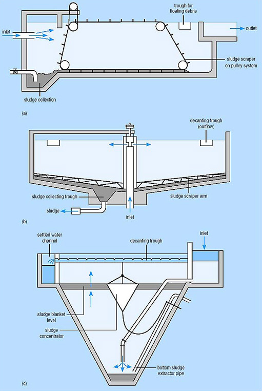
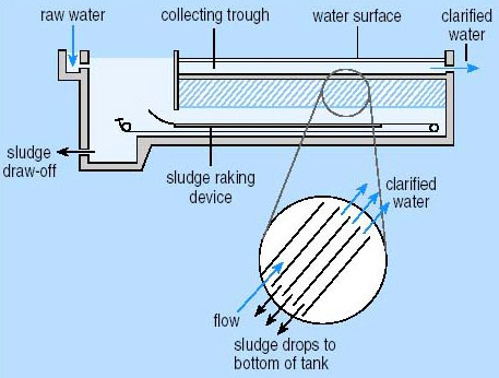
Sludge removal equipment includes mechanical rakes, drag-chain and flights, and traveling bridges. The chain and flight system is used in rectangular basins. A chain with scrappers attached moves across the bottom of the basin collecting sludge and moving it to a sump. This system works well but has several moving parts. Additionally, the basin must be dewatered to perform maintenance. The traveling bridge system is also used in a rectangular basin. It travels the entire length of the basin. A pump is attached to the bottom of the system and sludge is pumped to a trough just below the top of the sedimentation basin. The bridge system is easier to perform maintenance on because the parts can be removed from the basin; therefore, dewatering the entire basin isn’t required. Finally, mechanical rakes are used in rectangular or circular basins. A rake spans the entire length of the basin while spinning around the basin. Sludge is moved into a trough that can be pumped out or moved by gravity to a sludge collection tank.
Review and Daily Operations of Sedimentation Basins
In review, the purpose of sedimentation is to allow suspended solids to settle through the physical process of gravity. The flow of water is slowed down to allow settling to occur. During the process, sedimentation can remove 95% or more of the total solid material operators remove during the entire water treatment process.
Water treatment plants with low turbidity or fewer than 10 turbidity units may find direct filtration or clarification to be a more cost-effective process. A reoccurring theme that should be noted throughout the text is the fact that all treatment facilities are different and the factor that dictates plant processes including facility building and day to day operation is the source water.
The settling characteristics of suspended material dictates how well sedimentation performs. Flow rate through the sedimentation basin drives performance as well as the control of sludge. High flow rates cause solids to carry over, and could also impact the sludge at the bottom of the sedimentation basin. Operators must perform regular jar testing and laboratory testing as well as operate sedimentation basins based on the designed capacity of the basin to ensure optimal performance. Improper operation of sedimentation basins will lead to increased load on downstream filters resulting in early filter washes, increased disinfectant use, and possibly tier violations.
Velocity Math
The movement of water is obviously an important thing to know if you are a water treatment operator. You will need Algebra to solve the next set of water math problems which will have two known values and one unknown value. Flow rates can be used to determine dosage rates, to identify daily averages, to dewater pipelines, to fill pipelines, and for future planning of distribution and treatment equipment.
To solve a flow problem, you need the diameter of the pipe and the velocity of the water (or liquid) in the pipe. Flow rate is expressed as Volume over Time. The equation will be:
\[Q(Flow) = A(area) × V(velocity).\]
A velocity problem occurs when the known value is the pipe diameter and flow rate of pipe.
\[V(Velocity) = Q(Flow) ÷ A(Area). \]
Finally, pipe size is used when known value is pipe flow rate and velocity.
\[A(Area) = Q(Flow) ÷ V(Velocity).\]
Proper use of dimensional analysis is critical when attempting to solve velocity equations. These types of problems often take multiple steps because answers need to be converted to the appropriate units based on the situation.
Example \(\PageIndex{3}\)
A pipeline is 18” in diameter and flowing at a velocity of 125 ft per minute. What is the flow in gallons per minute?
Solution
Step one: Convert pipeline diameter to feet: 18 inches/(12 inches/foot) = 1.5 ft
Step Two: Q(Flow) = (.785)(1.5ft.)2(125 ft./min)
Step Three: 221 ft3 per minute × 7.48 gal/ft3 = 1651 gpm
Example \(\PageIndex{4}\)
The flow of a pipe is 2,000 gallons per minute. The diameter of pipe is 24”. What is the velocity of the pipe in ft. per minute?
Solution
Step one: Convert units 2,000 gpm ÷ 7.48 gal./ft3 = 267 ft3/min. 24 inches ÷ 12 inches/ft = 2 feet
Step two: V(velocity) = 267 ft3/min ÷ .785(2 ft.)2
Step three: V = 85 feet per minute
Example \(\PageIndex{5}\)
The velocity in a pipeline is 2 ft./sec. and the flow is 3,000 gpm. What is the diameter of the pipe in inches?
Solution
Step One: Convert flow to match units of measurement of velocity: 3,000 gal/min x 1 min/60 sec x 1 ft³/7.48 gal = 6.68 ft³/sec
Step two: Area= 6.68 ft³/sec ÷ 2 ft/sec= 3.3 feet
Step three: Convert feet to inches: 3.3 ft/1 × 12 inches/1 ft = 40 inches
Chapter Review
- The treatment process that involves coagulation, flocculation, sedimentation, and filtration is known as ___________.
- Direct filtration
- Slow sand filtration
- Conventional treatment
- Pressure filtration
- Sedimentation produces waste known as ___________.
- Backwash water
- Sludge
- Wastewater
- Mud
- What kind of process is the sedimentation step?
- Physical
- Chemical
- Biological
- Direct
- The weirs at the effluent of a sedimentation basin are also called ___________.
- Effluent weirs
- Baffling
- Launders
- Spokes
- Sedimentation is used in water treatment plants to ___________.
- Settle pathogenic material
- Destabilize particles
- Disinfect water
- Reduce loading on filters
- Scouring is a term that describes conditions in a sedimentation tank which ___________.
- Could impact the rest of the treatment process
- Higher flow rates in the sludge zone
- Re-suspends settle sludge
- All of the above
- The four zones in a Sedimentation basin include ___________.
- Inlet, sedimentation, sludge, outlet
- Inlet, filter, waste, outlet
- Inlet, top, bottom, outlet
- Surface, sedimentation, sludge, outlet
- Short-circuiting in a sedimentation basin could be caused by ___________.
- Surface wind
- Ineffective weir placement, or weirs covered in algae
- Poor baffling in sedimentation inlet zone
- All of the above
- How much solids should be removed during sedimentation?
- 95% or more
- 80-95%
- 70-80%
- 60-70%
- The type of basin that includes coagulation and flocculation is ___________.
- Rectangular
- Triangular
- Up-flow
- None of the above