5.3.4: Network Representations
- Page ID
- 22740
\( \newcommand{\vecs}[1]{\overset { \scriptstyle \rightharpoonup} {\mathbf{#1}} } \)
\( \newcommand{\vecd}[1]{\overset{-\!-\!\rightharpoonup}{\vphantom{a}\smash {#1}}} \)
\( \newcommand{\dsum}{\displaystyle\sum\limits} \)
\( \newcommand{\dint}{\displaystyle\int\limits} \)
\( \newcommand{\dlim}{\displaystyle\lim\limits} \)
\( \newcommand{\id}{\mathrm{id}}\) \( \newcommand{\Span}{\mathrm{span}}\)
( \newcommand{\kernel}{\mathrm{null}\,}\) \( \newcommand{\range}{\mathrm{range}\,}\)
\( \newcommand{\RealPart}{\mathrm{Re}}\) \( \newcommand{\ImaginaryPart}{\mathrm{Im}}\)
\( \newcommand{\Argument}{\mathrm{Arg}}\) \( \newcommand{\norm}[1]{\| #1 \|}\)
\( \newcommand{\inner}[2]{\langle #1, #2 \rangle}\)
\( \newcommand{\Span}{\mathrm{span}}\)
\( \newcommand{\id}{\mathrm{id}}\)
\( \newcommand{\Span}{\mathrm{span}}\)
\( \newcommand{\kernel}{\mathrm{null}\,}\)
\( \newcommand{\range}{\mathrm{range}\,}\)
\( \newcommand{\RealPart}{\mathrm{Re}}\)
\( \newcommand{\ImaginaryPart}{\mathrm{Im}}\)
\( \newcommand{\Argument}{\mathrm{Arg}}\)
\( \newcommand{\norm}[1]{\| #1 \|}\)
\( \newcommand{\inner}[2]{\langle #1, #2 \rangle}\)
\( \newcommand{\Span}{\mathrm{span}}\) \( \newcommand{\AA}{\unicode[.8,0]{x212B}}\)
\( \newcommand{\vectorA}[1]{\vec{#1}} % arrow\)
\( \newcommand{\vectorAt}[1]{\vec{\text{#1}}} % arrow\)
\( \newcommand{\vectorB}[1]{\overset { \scriptstyle \rightharpoonup} {\mathbf{#1}} } \)
\( \newcommand{\vectorC}[1]{\textbf{#1}} \)
\( \newcommand{\vectorD}[1]{\overrightarrow{#1}} \)
\( \newcommand{\vectorDt}[1]{\overrightarrow{\text{#1}}} \)
\( \newcommand{\vectE}[1]{\overset{-\!-\!\rightharpoonup}{\vphantom{a}\smash{\mathbf {#1}}}} \)
\( \newcommand{\vecs}[1]{\overset { \scriptstyle \rightharpoonup} {\mathbf{#1}} } \)
\(\newcommand{\longvect}{\overrightarrow}\)
\( \newcommand{\vecd}[1]{\overset{-\!-\!\rightharpoonup}{\vphantom{a}\smash {#1}}} \)
\(\newcommand{\avec}{\mathbf a}\) \(\newcommand{\bvec}{\mathbf b}\) \(\newcommand{\cvec}{\mathbf c}\) \(\newcommand{\dvec}{\mathbf d}\) \(\newcommand{\dtil}{\widetilde{\mathbf d}}\) \(\newcommand{\evec}{\mathbf e}\) \(\newcommand{\fvec}{\mathbf f}\) \(\newcommand{\nvec}{\mathbf n}\) \(\newcommand{\pvec}{\mathbf p}\) \(\newcommand{\qvec}{\mathbf q}\) \(\newcommand{\svec}{\mathbf s}\) \(\newcommand{\tvec}{\mathbf t}\) \(\newcommand{\uvec}{\mathbf u}\) \(\newcommand{\vvec}{\mathbf v}\) \(\newcommand{\wvec}{\mathbf w}\) \(\newcommand{\xvec}{\mathbf x}\) \(\newcommand{\yvec}{\mathbf y}\) \(\newcommand{\zvec}{\mathbf z}\) \(\newcommand{\rvec}{\mathbf r}\) \(\newcommand{\mvec}{\mathbf m}\) \(\newcommand{\zerovec}{\mathbf 0}\) \(\newcommand{\onevec}{\mathbf 1}\) \(\newcommand{\real}{\mathbb R}\) \(\newcommand{\twovec}[2]{\left[\begin{array}{r}#1 \\ #2 \end{array}\right]}\) \(\newcommand{\ctwovec}[2]{\left[\begin{array}{c}#1 \\ #2 \end{array}\right]}\) \(\newcommand{\threevec}[3]{\left[\begin{array}{r}#1 \\ #2 \\ #3 \end{array}\right]}\) \(\newcommand{\cthreevec}[3]{\left[\begin{array}{c}#1 \\ #2 \\ #3 \end{array}\right]}\) \(\newcommand{\fourvec}[4]{\left[\begin{array}{r}#1 \\ #2 \\ #3 \\ #4 \end{array}\right]}\) \(\newcommand{\cfourvec}[4]{\left[\begin{array}{c}#1 \\ #2 \\ #3 \\ #4 \end{array}\right]}\) \(\newcommand{\fivevec}[5]{\left[\begin{array}{r}#1 \\ #2 \\ #3 \\ #4 \\ #5 \\ \end{array}\right]}\) \(\newcommand{\cfivevec}[5]{\left[\begin{array}{c}#1 \\ #2 \\ #3 \\ #4 \\ #5 \\ \end{array}\right]}\) \(\newcommand{\mattwo}[4]{\left[\begin{array}{rr}#1 \amp #2 \\ #3 \amp #4 \\ \end{array}\right]}\) \(\newcommand{\laspan}[1]{\text{Span}\{#1\}}\) \(\newcommand{\bcal}{\cal B}\) \(\newcommand{\ccal}{\cal C}\) \(\newcommand{\scal}{\cal S}\) \(\newcommand{\wcal}{\cal W}\) \(\newcommand{\ecal}{\cal E}\) \(\newcommand{\coords}[2]{\left\{#1\right\}_{#2}}\) \(\newcommand{\gray}[1]{\color{gray}{#1}}\) \(\newcommand{\lgray}[1]{\color{lightgray}{#1}}\) \(\newcommand{\rank}{\operatorname{rank}}\) \(\newcommand{\row}{\text{Row}}\) \(\newcommand{\col}{\text{Col}}\) \(\renewcommand{\row}{\text{Row}}\) \(\newcommand{\nul}{\text{Nul}}\) \(\newcommand{\var}{\text{Var}}\) \(\newcommand{\corr}{\text{corr}}\) \(\newcommand{\len}[1]{\left|#1\right|}\) \(\newcommand{\bbar}{\overline{\bvec}}\) \(\newcommand{\bhat}{\widehat{\bvec}}\) \(\newcommand{\bperp}{\bvec^\perp}\) \(\newcommand{\xhat}{\widehat{\xvec}}\) \(\newcommand{\vhat}{\widehat{\vvec}}\) \(\newcommand{\uhat}{\widehat{\uvec}}\) \(\newcommand{\what}{\widehat{\wvec}}\) \(\newcommand{\Sighat}{\widehat{\Sigma}}\) \(\newcommand{\lt}{<}\) \(\newcommand{\gt}{>}\) \(\newcommand{\amp}{&}\) \(\definecolor{fillinmathshade}{gray}{0.9}\)To draw a diagram of a network, symbols are utilized by network professionals to represent the different devices and connections which make up a network.
A diagram gives a simple method to see how devices in a huge network are associated. This kind of "picture" of a network is known as a topology diagram. The capacity to perceive the legitimate portrayals of the physical systems administration segments is basic to have the option to imagine the association and activity of a network.
Notwithstanding these portrayals, particular phrasing is utilized while discussing how every one of these devices and media interfaces with one another. Significant terms to recall are:
- Network Interface Card: A NIC or LAN connector gives the physical association with the PC or opposite end device's network. The media that are associating the PC to the network administration device plug legitimately into the NIC.
- Physical Port: A connector or outlet on a network administration device where the media is associated with an end device or another network administration device.
- Interface: Specialized ports on a network administration device that associate with singular networks. Since switches are utilized to interconnect networks, the ports on a network allude to network interfaces.
Topology Diagrams
Understanding topology diagrams are required for anybody working with a network. They give a visual guide of how the network is associated.
There are two sorts of Topology diagrams:
- Physical topology and Logical topology diagrams. The physical topology diagrams identify the physical location of intermediary devices and cable installation.
- The Logical topology diagrams identify devices, addressing schemes, and ports.
With physical topology, it is quite self-explanatory. It is how they are interconnected with cables and wires physically. The logical topology is how connected devices are seen to the user.
There are three common network topologies being used, discussed below.
Star Network:

Figure \(\PageIndex{1}\): Star Topology used in a network. (2023, February 3) by Umapathy, via Wikipedia, is licensed CC BY-SA 3.0
The Star Network is one of the most common network topologies. It is a spoke-hub implement, meaning every node (devices, computers) is connected to a century hub. The hub acts as the mean to transmit messages. Twisted pair cable and optical fiber cables are commonly used to connect them.
One obvious advantage is if one node goes down, it does not affect other connections. A disadvantage is that the central hub is vulnerable since it is a single point of failure for the network. If the hub goes down, all nodes cannot transmit messages anymore.
Many home networks use the star topology to connect the devices in a home through a router (or hub).
Bus Network

The Bus Network uses a common backbone as a shared communication medium to connect all devices. It is an easy topology to set up since it only requires one backbone cable. However, if the backbone cable fails, the entire network stops working. It is best to use it to support a limited of devices.
Mesh Network

A Mesh Network is a local area network (LAN) topology where each node can connect directly to many other nodes and work together to transmit data. A full mesh is when every node connects to every other nodes. A partial mesh is when some nodes are connected indirectly through other nodes.
One advantage is the Mesh Network can be self-healed. It means that the network can still operate even when a node breaks down since the remaining nodes will find another efficient way to transmit data. It is preferred by organizations that want to have a reliable network.
Hybrid networks
Hybrid networks make use of the combination of the three networks above. For example, a Tree Topology integrates multiple star topologies.
Types of Networks
Networks foundations can vary regarding:
- Size of the territory secured
- Number of users connected
- Number and kinds of administrations accessible
- Territory of obligation
One key attribute to differentiate between different types is the size of the area it can serve.
| Network Types | Size of the territory |
|---|---|
|
A Personal Area Network (PAN) |
Connect devices close to one person (e.g., pairing Bluetooth headphones to a smartphone creates a PAN between those two devices |
|
A Local Area Network (LAN) Wireless LAN (WLAN) |
connects users and devices within a small area (e.g., an office or a home) |
|
A Metropolitan Area Network (MAN) |
connects users and their devices in an area that spans a campus or city |
|
A Wide Area Network (WAN) |
connects users and devices across large geographic regions (i.e., many states and countries) |
We will discuss the two most common networks: LAN and WAN.
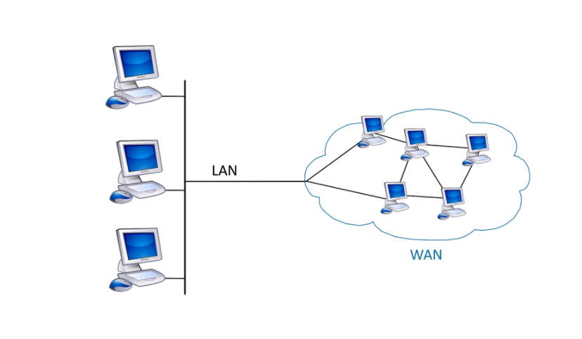
Local Area Networks
Figure \(\PageIndex{1}\) illustrates a Local Area Network (LAN) connecting devices together in a small geographical area such as a home, office, or campus. Some key features of LANs:
- LANs interconnect end-user devices like computers, printers, servers, and other equipment primarily within a single location.
- LANs are typically administered and managed by a single person or department, giving them control over security policies and access privileges on the network.
- LANs provide high-speed, reliable connectivity and throughput between connected devices, usually over Ethernet cabling or WiFi connections.
Ethernet is a widely used technology for local area networking. It specifies standards for connecting devices over copper cabling and sending data between them as electrical signals.

Wide Area Networks
Wide Area Networks (WANs) are a network foundation that traverses a wide topographical zone. WANs are ordinarily overseen by specialist organizations (SP) or Internet Service Providers (ISP).
Key features of WANs include:
- WANs interconnect LANs over wide geological zones, for example, between urban areas, states, territories, nations, or the mainland.
- Numerous specialist organizations typically manage WANs.
- WANs ordinarily give more slow speed joins between LANs