5.1: Make isometric sketches of simple rectangular objects
- Page ID
- 43365
\( \newcommand{\vecs}[1]{\overset { \scriptstyle \rightharpoonup} {\mathbf{#1}} } \)
\( \newcommand{\vecd}[1]{\overset{-\!-\!\rightharpoonup}{\vphantom{a}\smash {#1}}} \)
\( \newcommand{\id}{\mathrm{id}}\) \( \newcommand{\Span}{\mathrm{span}}\)
( \newcommand{\kernel}{\mathrm{null}\,}\) \( \newcommand{\range}{\mathrm{range}\,}\)
\( \newcommand{\RealPart}{\mathrm{Re}}\) \( \newcommand{\ImaginaryPart}{\mathrm{Im}}\)
\( \newcommand{\Argument}{\mathrm{Arg}}\) \( \newcommand{\norm}[1]{\| #1 \|}\)
\( \newcommand{\inner}[2]{\langle #1, #2 \rangle}\)
\( \newcommand{\Span}{\mathrm{span}}\)
\( \newcommand{\id}{\mathrm{id}}\)
\( \newcommand{\Span}{\mathrm{span}}\)
\( \newcommand{\kernel}{\mathrm{null}\,}\)
\( \newcommand{\range}{\mathrm{range}\,}\)
\( \newcommand{\RealPart}{\mathrm{Re}}\)
\( \newcommand{\ImaginaryPart}{\mathrm{Im}}\)
\( \newcommand{\Argument}{\mathrm{Arg}}\)
\( \newcommand{\norm}[1]{\| #1 \|}\)
\( \newcommand{\inner}[2]{\langle #1, #2 \rangle}\)
\( \newcommand{\Span}{\mathrm{span}}\) \( \newcommand{\AA}{\unicode[.8,0]{x212B}}\)
\( \newcommand{\vectorA}[1]{\vec{#1}} % arrow\)
\( \newcommand{\vectorAt}[1]{\vec{\text{#1}}} % arrow\)
\( \newcommand{\vectorB}[1]{\overset { \scriptstyle \rightharpoonup} {\mathbf{#1}} } \)
\( \newcommand{\vectorC}[1]{\textbf{#1}} \)
\( \newcommand{\vectorD}[1]{\overrightarrow{#1}} \)
\( \newcommand{\vectorDt}[1]{\overrightarrow{\text{#1}}} \)
\( \newcommand{\vectE}[1]{\overset{-\!-\!\rightharpoonup}{\vphantom{a}\smash{\mathbf {#1}}}} \)
\( \newcommand{\vecs}[1]{\overset { \scriptstyle \rightharpoonup} {\mathbf{#1}} } \)
\( \newcommand{\vecd}[1]{\overset{-\!-\!\rightharpoonup}{\vphantom{a}\smash {#1}}} \)
\(\newcommand{\avec}{\mathbf a}\) \(\newcommand{\bvec}{\mathbf b}\) \(\newcommand{\cvec}{\mathbf c}\) \(\newcommand{\dvec}{\mathbf d}\) \(\newcommand{\dtil}{\widetilde{\mathbf d}}\) \(\newcommand{\evec}{\mathbf e}\) \(\newcommand{\fvec}{\mathbf f}\) \(\newcommand{\nvec}{\mathbf n}\) \(\newcommand{\pvec}{\mathbf p}\) \(\newcommand{\qvec}{\mathbf q}\) \(\newcommand{\svec}{\mathbf s}\) \(\newcommand{\tvec}{\mathbf t}\) \(\newcommand{\uvec}{\mathbf u}\) \(\newcommand{\vvec}{\mathbf v}\) \(\newcommand{\wvec}{\mathbf w}\) \(\newcommand{\xvec}{\mathbf x}\) \(\newcommand{\yvec}{\mathbf y}\) \(\newcommand{\zvec}{\mathbf z}\) \(\newcommand{\rvec}{\mathbf r}\) \(\newcommand{\mvec}{\mathbf m}\) \(\newcommand{\zerovec}{\mathbf 0}\) \(\newcommand{\onevec}{\mathbf 1}\) \(\newcommand{\real}{\mathbb R}\) \(\newcommand{\twovec}[2]{\left[\begin{array}{r}#1 \\ #2 \end{array}\right]}\) \(\newcommand{\ctwovec}[2]{\left[\begin{array}{c}#1 \\ #2 \end{array}\right]}\) \(\newcommand{\threevec}[3]{\left[\begin{array}{r}#1 \\ #2 \\ #3 \end{array}\right]}\) \(\newcommand{\cthreevec}[3]{\left[\begin{array}{c}#1 \\ #2 \\ #3 \end{array}\right]}\) \(\newcommand{\fourvec}[4]{\left[\begin{array}{r}#1 \\ #2 \\ #3 \\ #4 \end{array}\right]}\) \(\newcommand{\cfourvec}[4]{\left[\begin{array}{c}#1 \\ #2 \\ #3 \\ #4 \end{array}\right]}\) \(\newcommand{\fivevec}[5]{\left[\begin{array}{r}#1 \\ #2 \\ #3 \\ #4 \\ #5 \\ \end{array}\right]}\) \(\newcommand{\cfivevec}[5]{\left[\begin{array}{c}#1 \\ #2 \\ #3 \\ #4 \\ #5 \\ \end{array}\right]}\) \(\newcommand{\mattwo}[4]{\left[\begin{array}{rr}#1 \amp #2 \\ #3 \amp #4 \\ \end{array}\right]}\) \(\newcommand{\laspan}[1]{\text{Span}\{#1\}}\) \(\newcommand{\bcal}{\cal B}\) \(\newcommand{\ccal}{\cal C}\) \(\newcommand{\scal}{\cal S}\) \(\newcommand{\wcal}{\cal W}\) \(\newcommand{\ecal}{\cal E}\) \(\newcommand{\coords}[2]{\left\{#1\right\}_{#2}}\) \(\newcommand{\gray}[1]{\color{gray}{#1}}\) \(\newcommand{\lgray}[1]{\color{lightgray}{#1}}\) \(\newcommand{\rank}{\operatorname{rank}}\) \(\newcommand{\row}{\text{Row}}\) \(\newcommand{\col}{\text{Col}}\) \(\renewcommand{\row}{\text{Row}}\) \(\newcommand{\nul}{\text{Nul}}\) \(\newcommand{\var}{\text{Var}}\) \(\newcommand{\corr}{\text{corr}}\) \(\newcommand{\len}[1]{\left|#1\right|}\) \(\newcommand{\bbar}{\overline{\bvec}}\) \(\newcommand{\bhat}{\widehat{\bvec}}\) \(\newcommand{\bperp}{\bvec^\perp}\) \(\newcommand{\xhat}{\widehat{\xvec}}\) \(\newcommand{\vhat}{\widehat{\vvec}}\) \(\newcommand{\uhat}{\widehat{\uvec}}\) \(\newcommand{\what}{\widehat{\wvec}}\) \(\newcommand{\Sighat}{\widehat{\Sigma}}\) \(\newcommand{\lt}{<}\) \(\newcommand{\gt}{>}\) \(\newcommand{\amp}{&}\) \(\definecolor{fillinmathshade}{gray}{0.9}\)Isometric sketches are helpful because they are easy to draw and clearly represent an object or system. This clarity comes from using directional lines to represent the three dimensions of length, width, and height, much like a picture.
Construction methods
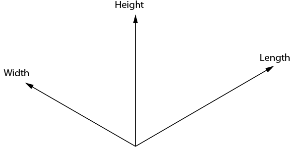
The following steps explain how to draw an isometric cube. The three dimensions of length, width, and height are drawn along the isometric axes shown in Figure \(\PageIndex{1}\). The lengths of objects running parallel to these axes can be drawn to scale. Lines at other angles will not be to scale.
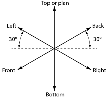
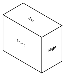
Draw a small star-shaped axis on the bottom corner of your grid paper. The sloping axes should be drawn at a 30-degree angle from the horizontal grid line. The vertical axis of the star indicates height (H) or depth (D), and the two sloping axes indicate the length (L) and the width (W) of the rectangle. The vertical axis can be used as a guide when making lines on your drawing. Notice we have labeled the points on the star in Figure \(\PageIndex{2}\). When drawing a stationary object, these labels can change depending on your desired view. The bottom two horizontal points indicate the view that is being drawn. In this case, we would be creating a front-right view.
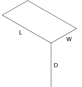
Sketch the top of the block by drawing two lines, one parallel to L and one parallel to W (Figure \(\PageIndex{3}\)).
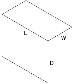
Sketch two lines, one parallel to L and one parallel to D, as shown in Figure \(\PageIndex{4}\).
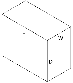
Sketch two lines, one parallel to W and one parallel to D, to complete the outline of the rectangular block as shown in Figure \(\PageIndex{5}\). Begin with light construction lines so that you can make any necessary adjustments before darkening them. Figure \(\PageIndex{6}\) shows the finished isometric sketch.
Sketching irregular shapes with isometric lines
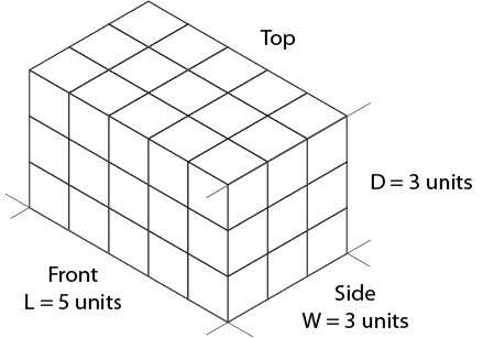
Not all rectangular objects are as simple as the block you have just sketched. Sometimes the shapes are irregular and have cut-out sections, or some sides longer than others. All rectangular objects can be fitted into a box having the maximum length (L), width (W), and depth (D). Begin by sketching a light outline of a basic box that is the size of the object to be drawn.
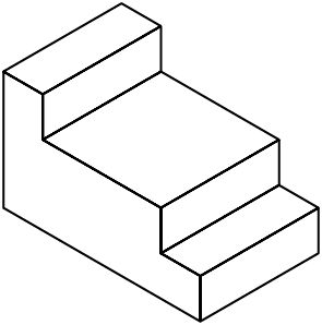
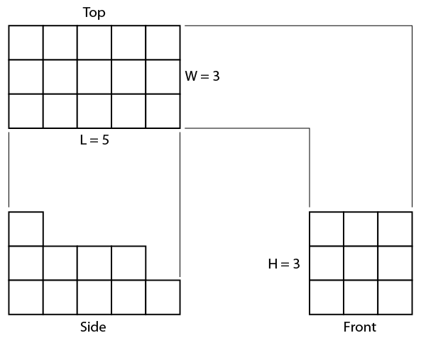
Consider the object shown in the three-view orthographic sketch in Figure \(\PageIndex{7}\). To produce an isometric sketch of this object, you need to find the maximum L, W, and D for the containing box (Figure \(\PageIndex{7}\)). In this case:
- L = 5 grid spaces
- W = 3 grid spaces
- D = 3 grid spaces
Sketch a light outline of the basic rectangular box to the required size, as shown in Figure \(\PageIndex{8}\).
The front view shows the outline most clearly. Place this view on the front surface of the isometric box. Use the dimension given in the front view of Figure \(\PageIndex{7}\) and mark the number of units indicated along the axes L and D (Figure \(\PageIndex{9}\)).
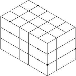
Lightly sketch lines parallel to the L and D axes from the marked points on the front surface (Figure \(\PageIndex{10}\)). Once you are sure your sketch is correct, the step outline is drawn more heavily to emphasize the object's profile.
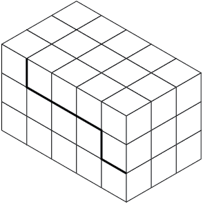
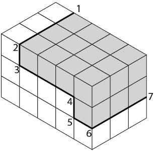
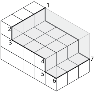
Sketch in a series of lines parallel to the axes (L, W, and D) from the corners numbered 1 to 7 (Figure \(\PageIndex{11}\)). These lines establish the stepped outline as shown in Figure \(\PageIndex{12}\).
When you are sure your isometric sketch is correct, erase all unnecessary construction lines and darken the object lines. Your completed sketch of the rectangular object should be similar to that in Figure \(\PageIndex{13}\).