
1.2: Types drawings
- Page ID
- 21960
\( \newcommand{\vecs}[1]{\overset { \scriptstyle \rightharpoonup} {\mathbf{#1}} } \)
\( \newcommand{\vecd}[1]{\overset{-\!-\!\rightharpoonup}{\vphantom{a}\smash {#1}}} \)
\( \newcommand{\dsum}{\displaystyle\sum\limits} \)
\( \newcommand{\dint}{\displaystyle\int\limits} \)
\( \newcommand{\dlim}{\displaystyle\lim\limits} \)
\( \newcommand{\id}{\mathrm{id}}\) \( \newcommand{\Span}{\mathrm{span}}\)
( \newcommand{\kernel}{\mathrm{null}\,}\) \( \newcommand{\range}{\mathrm{range}\,}\)
\( \newcommand{\RealPart}{\mathrm{Re}}\) \( \newcommand{\ImaginaryPart}{\mathrm{Im}}\)
\( \newcommand{\Argument}{\mathrm{Arg}}\) \( \newcommand{\norm}[1]{\| #1 \|}\)
\( \newcommand{\inner}[2]{\langle #1, #2 \rangle}\)
\( \newcommand{\Span}{\mathrm{span}}\)
\( \newcommand{\id}{\mathrm{id}}\)
\( \newcommand{\Span}{\mathrm{span}}\)
\( \newcommand{\kernel}{\mathrm{null}\,}\)
\( \newcommand{\range}{\mathrm{range}\,}\)
\( \newcommand{\RealPart}{\mathrm{Re}}\)
\( \newcommand{\ImaginaryPart}{\mathrm{Im}}\)
\( \newcommand{\Argument}{\mathrm{Arg}}\)
\( \newcommand{\norm}[1]{\| #1 \|}\)
\( \newcommand{\inner}[2]{\langle #1, #2 \rangle}\)
\( \newcommand{\Span}{\mathrm{span}}\) \( \newcommand{\AA}{\unicode[.8,0]{x212B}}\)
\( \newcommand{\vectorA}[1]{\vec{#1}} % arrow\)
\( \newcommand{\vectorAt}[1]{\vec{\text{#1}}} % arrow\)
\( \newcommand{\vectorB}[1]{\overset { \scriptstyle \rightharpoonup} {\mathbf{#1}} } \)
\( \newcommand{\vectorC}[1]{\textbf{#1}} \)
\( \newcommand{\vectorD}[1]{\overrightarrow{#1}} \)
\( \newcommand{\vectorDt}[1]{\overrightarrow{\text{#1}}} \)
\( \newcommand{\vectE}[1]{\overset{-\!-\!\rightharpoonup}{\vphantom{a}\smash{\mathbf {#1}}}} \)
\( \newcommand{\vecs}[1]{\overset { \scriptstyle \rightharpoonup} {\mathbf{#1}} } \)
\(\newcommand{\longvect}{\overrightarrow}\)
\( \newcommand{\vecd}[1]{\overset{-\!-\!\rightharpoonup}{\vphantom{a}\smash {#1}}} \)
\(\newcommand{\avec}{\mathbf a}\) \(\newcommand{\bvec}{\mathbf b}\) \(\newcommand{\cvec}{\mathbf c}\) \(\newcommand{\dvec}{\mathbf d}\) \(\newcommand{\dtil}{\widetilde{\mathbf d}}\) \(\newcommand{\evec}{\mathbf e}\) \(\newcommand{\fvec}{\mathbf f}\) \(\newcommand{\nvec}{\mathbf n}\) \(\newcommand{\pvec}{\mathbf p}\) \(\newcommand{\qvec}{\mathbf q}\) \(\newcommand{\svec}{\mathbf s}\) \(\newcommand{\tvec}{\mathbf t}\) \(\newcommand{\uvec}{\mathbf u}\) \(\newcommand{\vvec}{\mathbf v}\) \(\newcommand{\wvec}{\mathbf w}\) \(\newcommand{\xvec}{\mathbf x}\) \(\newcommand{\yvec}{\mathbf y}\) \(\newcommand{\zvec}{\mathbf z}\) \(\newcommand{\rvec}{\mathbf r}\) \(\newcommand{\mvec}{\mathbf m}\) \(\newcommand{\zerovec}{\mathbf 0}\) \(\newcommand{\onevec}{\mathbf 1}\) \(\newcommand{\real}{\mathbb R}\) \(\newcommand{\twovec}[2]{\left[\begin{array}{r}#1 \\ #2 \end{array}\right]}\) \(\newcommand{\ctwovec}[2]{\left[\begin{array}{c}#1 \\ #2 \end{array}\right]}\) \(\newcommand{\threevec}[3]{\left[\begin{array}{r}#1 \\ #2 \\ #3 \end{array}\right]}\) \(\newcommand{\cthreevec}[3]{\left[\begin{array}{c}#1 \\ #2 \\ #3 \end{array}\right]}\) \(\newcommand{\fourvec}[4]{\left[\begin{array}{r}#1 \\ #2 \\ #3 \\ #4 \end{array}\right]}\) \(\newcommand{\cfourvec}[4]{\left[\begin{array}{c}#1 \\ #2 \\ #3 \\ #4 \end{array}\right]}\) \(\newcommand{\fivevec}[5]{\left[\begin{array}{r}#1 \\ #2 \\ #3 \\ #4 \\ #5 \\ \end{array}\right]}\) \(\newcommand{\cfivevec}[5]{\left[\begin{array}{c}#1 \\ #2 \\ #3 \\ #4 \\ #5 \\ \end{array}\right]}\) \(\newcommand{\mattwo}[4]{\left[\begin{array}{rr}#1 \amp #2 \\ #3 \amp #4 \\ \end{array}\right]}\) \(\newcommand{\laspan}[1]{\text{Span}\{#1\}}\) \(\newcommand{\bcal}{\cal B}\) \(\newcommand{\ccal}{\cal C}\) \(\newcommand{\scal}{\cal S}\) \(\newcommand{\wcal}{\cal W}\) \(\newcommand{\ecal}{\cal E}\) \(\newcommand{\coords}[2]{\left\{#1\right\}_{#2}}\) \(\newcommand{\gray}[1]{\color{gray}{#1}}\) \(\newcommand{\lgray}[1]{\color{lightgray}{#1}}\) \(\newcommand{\rank}{\operatorname{rank}}\) \(\newcommand{\row}{\text{Row}}\) \(\newcommand{\col}{\text{Col}}\) \(\renewcommand{\row}{\text{Row}}\) \(\newcommand{\nul}{\text{Nul}}\) \(\newcommand{\var}{\text{Var}}\) \(\newcommand{\corr}{\text{corr}}\) \(\newcommand{\len}[1]{\left|#1\right|}\) \(\newcommand{\bbar}{\overline{\bvec}}\) \(\newcommand{\bhat}{\widehat{\bvec}}\) \(\newcommand{\bperp}{\bvec^\perp}\) \(\newcommand{\xhat}{\widehat{\xvec}}\) \(\newcommand{\vhat}{\widehat{\vvec}}\) \(\newcommand{\uhat}{\widehat{\uvec}}\) \(\newcommand{\what}{\widehat{\wvec}}\) \(\newcommand{\Sighat}{\widehat{\Sigma}}\) \(\newcommand{\lt}{<}\) \(\newcommand{\gt}{>}\) \(\newcommand{\amp}{&}\) \(\definecolor{fillinmathshade}{gray}{0.9}\)Drawings are made according to a set of conventions, which include particular views (floor plan, section, etc.), sheet sizes, units of measurement and scales, annotation, and cross-referencing.
The two main types of views (or “projections”) used in drawings are:
- Pictorial
- Orthographic
- Building Plans
Pictorial views
Pictorial views show a 3-D view of how something should look when completed. There are three types of pictorial views:
- Perspective
- Isometric
- Oblique
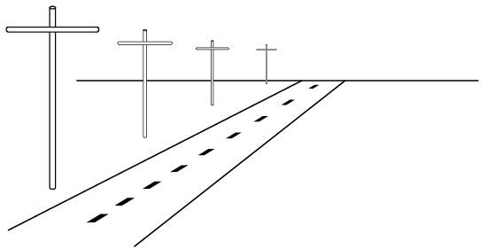
Perspective view
Perspective is the most realistic form of drawing. Artists use one-point perspective, two-point (shown here), and three-point to create visual depth. Perspectives are used by architects and for industrial pictorials of plan layouts, machinery, and other subjects where realism is required.
A perspective view presents a building or an object just as it would look to you. A perspective view has a vanishing point; that is, lines that move away from you come together in the distance. For example, in Figure 1, we see a road and a line of telephone poles. Even though the poles get smaller in their actual measurement, we recognize them as being the same size but more distant.
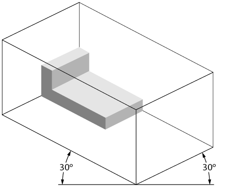
Isometric
An isometric view is a three-dimensional view. The plumb lines are vertical, and the horizontal lines are set at 30-degree angles from a line parallel to the bottom of the page. Isometric views have no vanishing point, so the objects do not appear as they would in a perspective view. Lengths are exact on isometric drawings only when the item is parallel to one of the axes of the drawing. Figure 2 shows an isometric view of a simple object, as well as the lines that represent the three dimensions.
These are the most used type of drawings in the piping industry and take a good deal of practice to fully understand how to draw. They best represent what is being built and what it will look like from the different sides with one drawing.
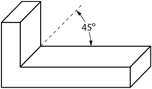
Oblique
An oblique view is similar to an isometric view, except that the face or front view is drawn to an exact scale. The diagonal lines are extended at a 30- to 45-degree angle to create a three-dimensional representation (Figure 3). The angled lines can then either be to an exact scale (Cavalier Oblique) or 1/2 scale (Cabinet Oblique).
Orthographic (Multi-view) Projections
Pictorial drawings are excellent for presenting easy-to-visualize pictures to the viewer, but there are some problems. The main problem is that pictorial drawings cannot be accurately drawn to scale. Also, they cannot accurately duplicate exact shapes and angles. As this information can be essential, another form of drawing is used, one that has several names, including orthographic projection, third angle projection, multi-view projection, and working drawing. Each projection is a view that shows only one face of an object, such as the front, side, top, or back. These views are not pictorial.
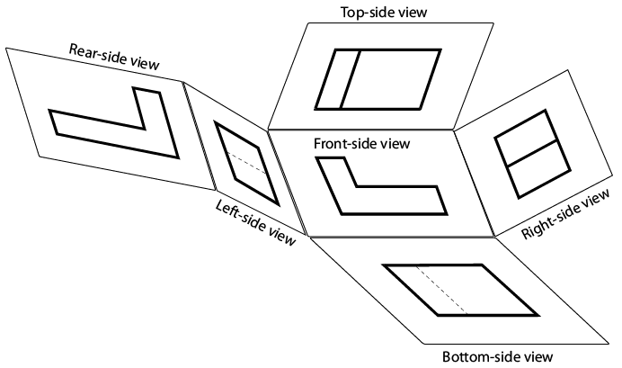
To interpret or read these drawings you must first understand how the views in a multi-view drawing are developed and how each view relates to the other views. The best way to understand the principle of orthographic views is to suspend the object you wish to draw inside an imaginary glass box. If you were to look at the object through each side of the box and draw onto the glass the view of the object you see through the glass, you would end up with a sketch similar to that shown in Figure 4.
The view through each side of the glass box shows only the end view of one side of the object. All lines are straight and parallel because the original object has sides that are straight and parallel. Each view represents what you see when you look directly at the object.
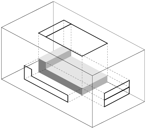
If you were to open up the glass box, as shown in Figure 5, each view would be in the correct position for a third angle orthographic drawing. Each view is given a name that reflects its position in relation to the other views.
Third angle projections are what are commonly used in North America, while first angle is often used in Europe is the object is "viewed" from the center out.
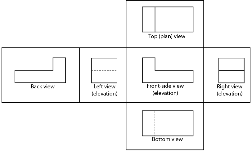
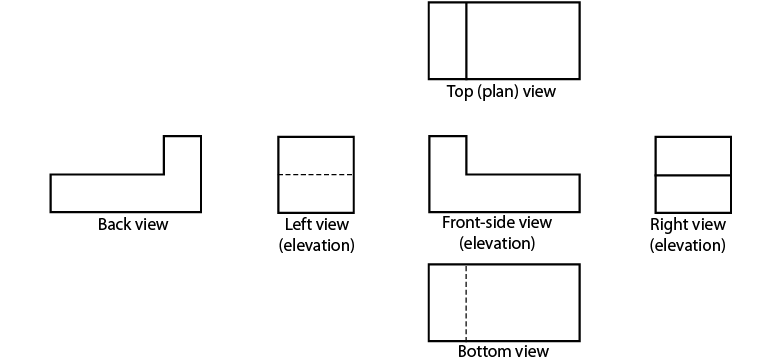
When the imaginary glass box is flattened as shown in Figure 6, you can see that each view is in line with the adjacent view. Then the edges of the box are removed and you have a six-view orthographic drawing of the original object (Figure 7). These six views are called the six principal orthographic views. This view alignment is important and is always consistent in orthographic projection. You will seldom need to show views of all six sides of an object. Usually, it is sufficient to show three; top, front, and right side. While simpler objects like bars could possibly be shown in two, or a ball only in one. You should remember the names of these six views and understand how they are obtained in case you ever need to show an object that cannot be truly represented in two or three views.
Building Plans
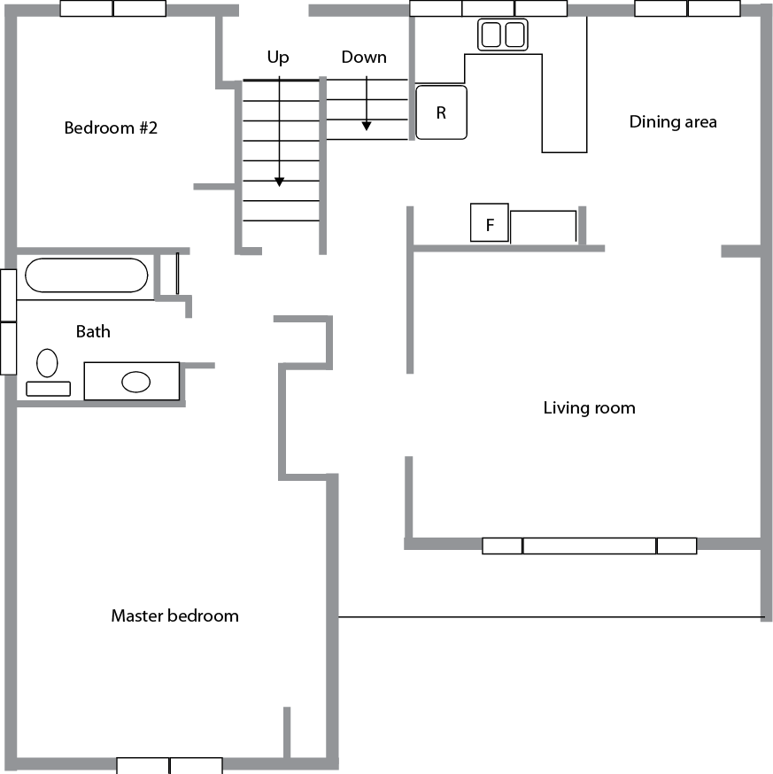
A floor plan (or floor drawing) is an orthographic plan view (or top view) looking down on the various floor levels. Floor plans are one of the most important drawings for construction, as they provide the most information about the building. Floor plans identify rooms by name or number.
They give the:
- room dimensions
- overall dimensions
- doorways
- windows
- plumbing fixtures
- equipment
- location of structural members and walls Figure 8 shows the floor plan for the main floor of a house.
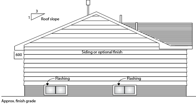
Elevation drawings
An elevation drawing (called an elevation) is a view of any vertical surface and is taken from the floor plans (Figure 9). Normally, elevation drawings include the front, back, and side orthographic projections of the buildings. The elevation drawings show what the exterior of the building will look like when it is finished. The drawings show the finished grade line, the finish materials, and the door and the window locations. Elevation drawings may also show interior walls that have special features, such as fireplaces or kitchen cabinets.
Section plan
Section drawings (called sections) provide detailed drawings of the cross-section of a building or wall unit (Figure 10). The scale of these drawings is large (about 1:20), which allows different structural members to be drawn so that the construction details are seen clearly.
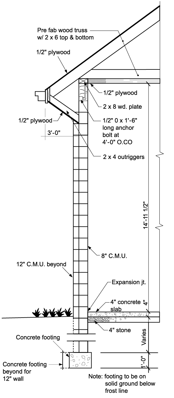
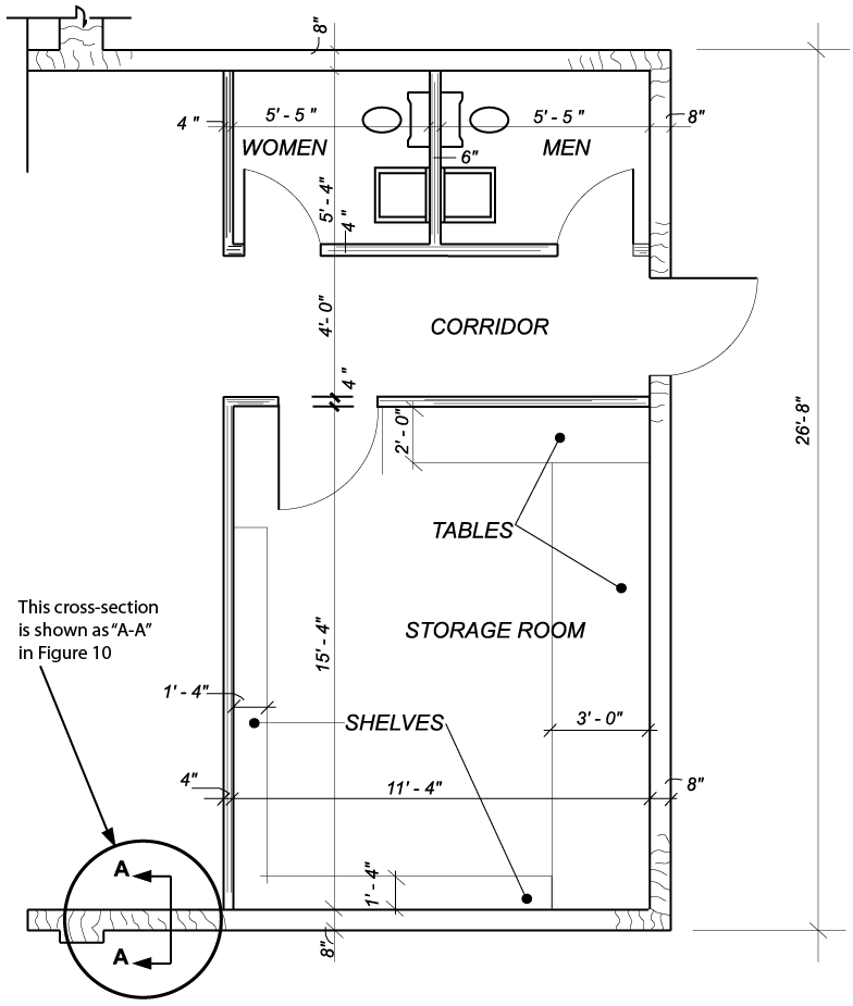
Sectional views give information about wall construction and exterior and interior wall finish. To avoid any confusion, the precise location or cut of a sectional view is given in another drawing, such as a detailed drawing or a floor plan. For example, the reference in the lower left-hand corner of Figure 11 shows the location of the section in Figure 10. The line drawn through the wall indicates the point and span of the cut and the arrows indicate the direction of view.
Measurements on orthographic drawings
To get all of the measurements required, you will typically need to refer to more than one view. For example, you cannot take elevation measurements from a plan view.