
4.7: Component Failure Analysis
- Page ID
- 17331

\( \newcommand{\vecs}[1]{\overset { \scriptstyle \rightharpoonup} {\mathbf{#1}} } \)
\( \newcommand{\vecd}[1]{\overset{-\!-\!\rightharpoonup}{\vphantom{a}\smash {#1}}} \)
\( \newcommand{\id}{\mathrm{id}}\) \( \newcommand{\Span}{\mathrm{span}}\)
( \newcommand{\kernel}{\mathrm{null}\,}\) \( \newcommand{\range}{\mathrm{range}\,}\)
\( \newcommand{\RealPart}{\mathrm{Re}}\) \( \newcommand{\ImaginaryPart}{\mathrm{Im}}\)
\( \newcommand{\Argument}{\mathrm{Arg}}\) \( \newcommand{\norm}[1]{\| #1 \|}\)
\( \newcommand{\inner}[2]{\langle #1, #2 \rangle}\)
\( \newcommand{\Span}{\mathrm{span}}\)
\( \newcommand{\id}{\mathrm{id}}\)
\( \newcommand{\Span}{\mathrm{span}}\)
\( \newcommand{\kernel}{\mathrm{null}\,}\)
\( \newcommand{\range}{\mathrm{range}\,}\)
\( \newcommand{\RealPart}{\mathrm{Re}}\)
\( \newcommand{\ImaginaryPart}{\mathrm{Im}}\)
\( \newcommand{\Argument}{\mathrm{Arg}}\)
\( \newcommand{\norm}[1]{\| #1 \|}\)
\( \newcommand{\inner}[2]{\langle #1, #2 \rangle}\)
\( \newcommand{\Span}{\mathrm{span}}\) \( \newcommand{\AA}{\unicode[.8,0]{x212B}}\)
\( \newcommand{\vectorA}[1]{\vec{#1}} % arrow\)
\( \newcommand{\vectorAt}[1]{\vec{\text{#1}}} % arrow\)
\( \newcommand{\vectorB}[1]{\overset { \scriptstyle \rightharpoonup} {\mathbf{#1}} } \)
\( \newcommand{\vectorC}[1]{\textbf{#1}} \)
\( \newcommand{\vectorD}[1]{\overrightarrow{#1}} \)
\( \newcommand{\vectorDt}[1]{\overrightarrow{\text{#1}}} \)
\( \newcommand{\vectE}[1]{\overset{-\!-\!\rightharpoonup}{\vphantom{a}\smash{\mathbf {#1}}}} \)
\( \newcommand{\vecs}[1]{\overset { \scriptstyle \rightharpoonup} {\mathbf{#1}} } \)
\( \newcommand{\vecd}[1]{\overset{-\!-\!\rightharpoonup}{\vphantom{a}\smash {#1}}} \)
\(\newcommand{\avec}{\mathbf a}\) \(\newcommand{\bvec}{\mathbf b}\) \(\newcommand{\cvec}{\mathbf c}\) \(\newcommand{\dvec}{\mathbf d}\) \(\newcommand{\dtil}{\widetilde{\mathbf d}}\) \(\newcommand{\evec}{\mathbf e}\) \(\newcommand{\fvec}{\mathbf f}\) \(\newcommand{\nvec}{\mathbf n}\) \(\newcommand{\pvec}{\mathbf p}\) \(\newcommand{\qvec}{\mathbf q}\) \(\newcommand{\svec}{\mathbf s}\) \(\newcommand{\tvec}{\mathbf t}\) \(\newcommand{\uvec}{\mathbf u}\) \(\newcommand{\vvec}{\mathbf v}\) \(\newcommand{\wvec}{\mathbf w}\) \(\newcommand{\xvec}{\mathbf x}\) \(\newcommand{\yvec}{\mathbf y}\) \(\newcommand{\zvec}{\mathbf z}\) \(\newcommand{\rvec}{\mathbf r}\) \(\newcommand{\mvec}{\mathbf m}\) \(\newcommand{\zerovec}{\mathbf 0}\) \(\newcommand{\onevec}{\mathbf 1}\) \(\newcommand{\real}{\mathbb R}\) \(\newcommand{\twovec}[2]{\left[\begin{array}{r}#1 \\ #2 \end{array}\right]}\) \(\newcommand{\ctwovec}[2]{\left[\begin{array}{c}#1 \\ #2 \end{array}\right]}\) \(\newcommand{\threevec}[3]{\left[\begin{array}{r}#1 \\ #2 \\ #3 \end{array}\right]}\) \(\newcommand{\cthreevec}[3]{\left[\begin{array}{c}#1 \\ #2 \\ #3 \end{array}\right]}\) \(\newcommand{\fourvec}[4]{\left[\begin{array}{r}#1 \\ #2 \\ #3 \\ #4 \end{array}\right]}\) \(\newcommand{\cfourvec}[4]{\left[\begin{array}{c}#1 \\ #2 \\ #3 \\ #4 \end{array}\right]}\) \(\newcommand{\fivevec}[5]{\left[\begin{array}{r}#1 \\ #2 \\ #3 \\ #4 \\ #5 \\ \end{array}\right]}\) \(\newcommand{\cfivevec}[5]{\left[\begin{array}{c}#1 \\ #2 \\ #3 \\ #4 \\ #5 \\ \end{array}\right]}\) \(\newcommand{\mattwo}[4]{\left[\begin{array}{rr}#1 \amp #2 \\ #3 \amp #4 \\ \end{array}\right]}\) \(\newcommand{\laspan}[1]{\text{Span}\{#1\}}\) \(\newcommand{\bcal}{\cal B}\) \(\newcommand{\ccal}{\cal C}\) \(\newcommand{\scal}{\cal S}\) \(\newcommand{\wcal}{\cal W}\) \(\newcommand{\ecal}{\cal E}\) \(\newcommand{\coords}[2]{\left\{#1\right\}_{#2}}\) \(\newcommand{\gray}[1]{\color{gray}{#1}}\) \(\newcommand{\lgray}[1]{\color{lightgray}{#1}}\) \(\newcommand{\rank}{\operatorname{rank}}\) \(\newcommand{\row}{\text{Row}}\) \(\newcommand{\col}{\text{Col}}\) \(\renewcommand{\row}{\text{Row}}\) \(\newcommand{\nul}{\text{Nul}}\) \(\newcommand{\var}{\text{Var}}\) \(\newcommand{\corr}{\text{corr}}\) \(\newcommand{\len}[1]{\left|#1\right|}\) \(\newcommand{\bbar}{\overline{\bvec}}\) \(\newcommand{\bhat}{\widehat{\bvec}}\) \(\newcommand{\bperp}{\bvec^\perp}\) \(\newcommand{\xhat}{\widehat{\xvec}}\) \(\newcommand{\vhat}{\widehat{\vvec}}\) \(\newcommand{\uhat}{\widehat{\uvec}}\) \(\newcommand{\what}{\widehat{\wvec}}\) \(\newcommand{\Sighat}{\widehat{\Sigma}}\) \(\newcommand{\lt}{<}\) \(\newcommand{\gt}{>}\) \(\newcommand{\amp}{&}\) \(\definecolor{fillinmathshade}{gray}{0.9}\)The job of a technician frequently entails “troubleshooting” (locating and correcting a problem) in malfunctioning circuits. Good troubleshooting is a demanding and rewarding effort, requiring a thorough understanding of the basic concepts, the ability to formulate hypotheses (proposed explanations of an effect), the ability to judge the value of different hypotheses based on their probability (how likely one particular cause may be over another), and a sense of creativity in applying a solution to rectify the problem. While it is possible to distill these skills into a scientific methodology, most practiced troubleshooters would agree that troubleshooting involves a touch of art, and that it can take years of experience to fully develop this art.
An essential skill to have is a ready and intuitive understanding of how component faults affect circuits in different configurations. We will explore some of the effects of component faults in both series and parallel circuits here, then to a greater degree at the end of the “Series-Parallel Combination Circuits” chapter.
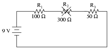
Let’s start with a simple series circuit:
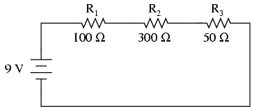
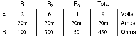
With all components in this circuit functioning at their proper values, we can mathematically determine all currents and voltage drops:
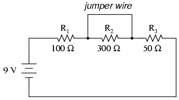
Now let us suppose that R2 fails shorted. Shorted means that the resistor now acts like a straight piece of wire, with little or no resistance. The circuit will behave as though a “jumper” wire were connected across R2(in case you were wondering, “jumper wire” is a common term for a temporary wire connection in a circuit). What causes the shorted condition of R2 is no matter to us in this example; we only care about its effect upon the circuit:
With R2 shorted, either by a jumper wire or by an internal resistor failure, the total circuit resistance will decrease. Since the voltage output by the battery is a constant (at least in our ideal simulation here), a decrease in total circuit resistance means that total circuit current must increase:
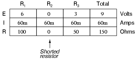
As the circuit current increases from 20 milliamps to 60 milliamps, the voltage drops across R1 and R3(which haven’t changed resistances) increase as well, so that the two resistors are dropping the whole 9 volts. R2, being bypassed by the very low resistance of the jumper wire, is effectively eliminated from the circuit, the resistance from one lead to the other having been reduced to zero. Thus, the voltage drop across R2, even with the increased total current, is zero volts.
On the other hand, if R2 were to fail “open”—resistance increasing to nearly infinite levels—it would also create wide-reaching effects in the rest of the circuit:
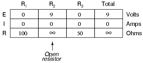
With R2 at infinite resistance and total resistance being the sum of all individual resistances in a series circuit, the total current decreases to zero. With zero circuit current, there is no electron flow to produce voltage drops across R1 or R3. R2, on the other hand, will manifest the full supply voltage across its terminals.
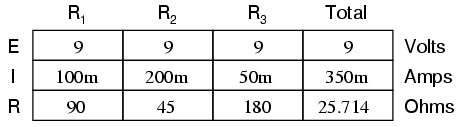
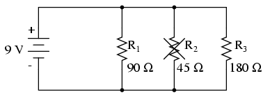
We can apply the same before/after analysis technique to parallel circuits as well. First, we determine what a “healthy” parallel circuit should behave like.
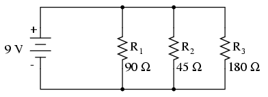
Supposing that R2 opens in this parallel circuit, here’s what the effects will be:
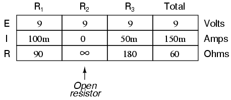
Notice that in this parallel circuit, an open branch only affects the current through that branch and the circuit’s total current. Total voltage—being shared equally across all components in a parallel circuit, will be the same for all resistors. Due to the fact that the voltage source’s tendency is to hold voltage constant, its voltage will not change, and being in parallel with all the resistors, it will hold all the resistors’ voltages the same as they were before: 9 volts. Being that voltage is the only common parameter in a parallel circuit, and the other resistors haven’t changed resistance value, their respective branch currents remain unchanged.
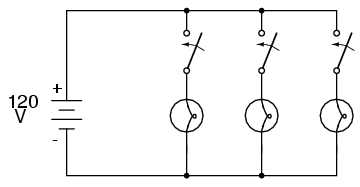
This is what happens in a household lamp circuit: all lamps get their operating voltage from power wiring arranged in a parallel fashion. Turning one lamp on and off (one branch in that parallel circuit closing and opening) doesn’t affect the operation of other lamps in the room, only the current in that one lamp (branch circuit) and the total current powering all the lamps in the room:
In an ideal case (with perfect voltage sources and zero-resistance connecting wire), shorted resistors in a simple parallel circuit will also have no effect on what’s happening in other branches of the circuit. In real life, the effect is not quite the same, and we’ll see why in the following example:
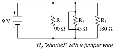
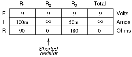
A shorted resistor (resistance of 0 Ω) would theoretically draw infinite current from any finite source of voltage (I=E/0). In this case, the zero resistance of R2 decreases the circuit total resistance to zero Ω as well, increasing total current to a value of infinity. As long as the voltage source holds steady at 9 volts, however, the other branch currents (IR1 and IR3) will remain unchanged.
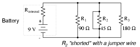
The critical assumption in this “perfect” scheme, however, is that the voltage supply will hold steady at its rated voltage while supplying an infinite amount of current to a short-circuit load. This is simply not realistic. Even if the short has a small amount of resistance (as opposed to absolutely zero resistance), no real voltage source could arbitrarily supply a huge overload current and maintain steady voltage at the same time. This is primarily due to the internal resistance intrinsic to all electrical power sources, stemming from the inescapable physical properties of the materials they’re constructed of:
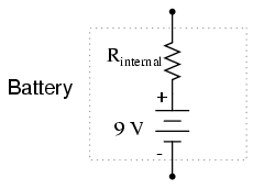
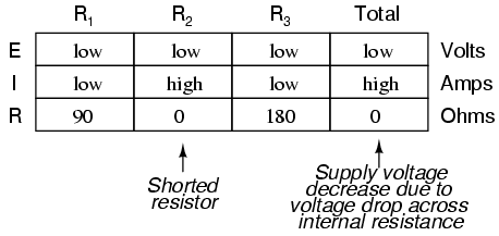
These internal resistances, small as they may be, turn our simple parallel circuit into a series-parallel combination circuit. Usually, the internal resistances of voltage sources are low enough that they can be safely ignored, but when high currents resulting from shorted components are encountered, their effects become very noticeable. In this case, a shorted R2 would result in almost all the voltage being dropped across the internal resistance of the battery, with almost no voltage left over for resistors R1, R2, and R3:
Suffice it to say, intentional direct short-circuits across the terminals of any voltage source is a bad idea. Even if the resulting high current (heat, flashes, sparks) causes no harm to people nearby, the voltage source will likely sustain damage, unless it has been specifically designed to handle short-circuits, which most voltage sources are not.
Eventually in this book I will lead you through the analysis of circuits without the use of any numbers, that is, analyzing the effects of component failure in a circuit without knowing exactly how many volts the battery produces, how many ohms of resistance is in each resistor, etc. This section serves as an introductory step to that kind of analysis.
Whereas the normal application of Ohm’s Law and the rules of series and parallel circuits is performed with numerical quantities (“quantitative”), this new kind of analysis without precise numerical figures is something I like to call qualitative analysis. In other words, we will be analyzing the qualities of the effects in a circuit rather than the precise quantities. The result, for you, will be a much deeper intuitive understanding of electric circuit operation.
Review
- To determine what would happen in a circuit if a component fails, re-draw that circuit with the equivalent resistance of the failed component in place and re-calculate all values.
- The ability to intuitively determine what will happen to a circuit with any given component fault is a crucial skill for any electronics troubleshooter to develop. The best way to learn is to experiment with circuit calculations and real-life circuits, paying close attention to what changes with a fault, what remains the same, and why!
- A shorted component is one whose resistance has dramatically decreased.
- An open component is one whose resistance has dramatically increased. For the record, resistors tend to fail open more often than fail shorted, and they almost never fail unless physically or electrically overstressed (physically abused or overheated).