6.3: Electrophotography
- Page ID
- 9544
\( \newcommand{\vecs}[1]{\overset { \scriptstyle \rightharpoonup} {\mathbf{#1}} } \)
\( \newcommand{\vecd}[1]{\overset{-\!-\!\rightharpoonup}{\vphantom{a}\smash {#1}}} \)
\( \newcommand{\id}{\mathrm{id}}\) \( \newcommand{\Span}{\mathrm{span}}\)
( \newcommand{\kernel}{\mathrm{null}\,}\) \( \newcommand{\range}{\mathrm{range}\,}\)
\( \newcommand{\RealPart}{\mathrm{Re}}\) \( \newcommand{\ImaginaryPart}{\mathrm{Im}}\)
\( \newcommand{\Argument}{\mathrm{Arg}}\) \( \newcommand{\norm}[1]{\| #1 \|}\)
\( \newcommand{\inner}[2]{\langle #1, #2 \rangle}\)
\( \newcommand{\Span}{\mathrm{span}}\)
\( \newcommand{\id}{\mathrm{id}}\)
\( \newcommand{\Span}{\mathrm{span}}\)
\( \newcommand{\kernel}{\mathrm{null}\,}\)
\( \newcommand{\range}{\mathrm{range}\,}\)
\( \newcommand{\RealPart}{\mathrm{Re}}\)
\( \newcommand{\ImaginaryPart}{\mathrm{Im}}\)
\( \newcommand{\Argument}{\mathrm{Arg}}\)
\( \newcommand{\norm}[1]{\| #1 \|}\)
\( \newcommand{\inner}[2]{\langle #1, #2 \rangle}\)
\( \newcommand{\Span}{\mathrm{span}}\) \( \newcommand{\AA}{\unicode[.8,0]{x212B}}\)
\( \newcommand{\vectorA}[1]{\vec{#1}} % arrow\)
\( \newcommand{\vectorAt}[1]{\vec{\text{#1}}} % arrow\)
\( \newcommand{\vectorB}[1]{\overset { \scriptstyle \rightharpoonup} {\mathbf{#1}} } \)
\( \newcommand{\vectorC}[1]{\textbf{#1}} \)
\( \newcommand{\vectorD}[1]{\overrightarrow{#1}} \)
\( \newcommand{\vectorDt}[1]{\overrightarrow{\text{#1}}} \)
\( \newcommand{\vectE}[1]{\overset{-\!-\!\rightharpoonup}{\vphantom{a}\smash{\mathbf {#1}}}} \)
\( \newcommand{\vecs}[1]{\overset { \scriptstyle \rightharpoonup} {\mathbf{#1}} } \)
\( \newcommand{\vecd}[1]{\overset{-\!-\!\rightharpoonup}{\vphantom{a}\smash {#1}}} \)
\(\newcommand{\avec}{\mathbf a}\) \(\newcommand{\bvec}{\mathbf b}\) \(\newcommand{\cvec}{\mathbf c}\) \(\newcommand{\dvec}{\mathbf d}\) \(\newcommand{\dtil}{\widetilde{\mathbf d}}\) \(\newcommand{\evec}{\mathbf e}\) \(\newcommand{\fvec}{\mathbf f}\) \(\newcommand{\nvec}{\mathbf n}\) \(\newcommand{\pvec}{\mathbf p}\) \(\newcommand{\qvec}{\mathbf q}\) \(\newcommand{\svec}{\mathbf s}\) \(\newcommand{\tvec}{\mathbf t}\) \(\newcommand{\uvec}{\mathbf u}\) \(\newcommand{\vvec}{\mathbf v}\) \(\newcommand{\wvec}{\mathbf w}\) \(\newcommand{\xvec}{\mathbf x}\) \(\newcommand{\yvec}{\mathbf y}\) \(\newcommand{\zvec}{\mathbf z}\) \(\newcommand{\rvec}{\mathbf r}\) \(\newcommand{\mvec}{\mathbf m}\) \(\newcommand{\zerovec}{\mathbf 0}\) \(\newcommand{\onevec}{\mathbf 1}\) \(\newcommand{\real}{\mathbb R}\) \(\newcommand{\twovec}[2]{\left[\begin{array}{r}#1 \\ #2 \end{array}\right]}\) \(\newcommand{\ctwovec}[2]{\left[\begin{array}{c}#1 \\ #2 \end{array}\right]}\) \(\newcommand{\threevec}[3]{\left[\begin{array}{r}#1 \\ #2 \\ #3 \end{array}\right]}\) \(\newcommand{\cthreevec}[3]{\left[\begin{array}{c}#1 \\ #2 \\ #3 \end{array}\right]}\) \(\newcommand{\fourvec}[4]{\left[\begin{array}{r}#1 \\ #2 \\ #3 \\ #4 \end{array}\right]}\) \(\newcommand{\cfourvec}[4]{\left[\begin{array}{c}#1 \\ #2 \\ #3 \\ #4 \end{array}\right]}\) \(\newcommand{\fivevec}[5]{\left[\begin{array}{r}#1 \\ #2 \\ #3 \\ #4 \\ #5 \\ \end{array}\right]}\) \(\newcommand{\cfivevec}[5]{\left[\begin{array}{c}#1 \\ #2 \\ #3 \\ #4 \\ #5 \\ \end{array}\right]}\) \(\newcommand{\mattwo}[4]{\left[\begin{array}{rr}#1 \amp #2 \\ #3 \amp #4 \\ \end{array}\right]}\) \(\newcommand{\laspan}[1]{\text{Span}\{#1\}}\) \(\newcommand{\bcal}{\cal B}\) \(\newcommand{\ccal}{\cal C}\) \(\newcommand{\scal}{\cal S}\) \(\newcommand{\wcal}{\cal W}\) \(\newcommand{\ecal}{\cal E}\) \(\newcommand{\coords}[2]{\left\{#1\right\}_{#2}}\) \(\newcommand{\gray}[1]{\color{gray}{#1}}\) \(\newcommand{\lgray}[1]{\color{lightgray}{#1}}\) \(\newcommand{\rank}{\operatorname{rank}}\) \(\newcommand{\row}{\text{Row}}\) \(\newcommand{\col}{\text{Col}}\) \(\renewcommand{\row}{\text{Row}}\) \(\newcommand{\nul}{\text{Nul}}\) \(\newcommand{\var}{\text{Var}}\) \(\newcommand{\corr}{\text{corr}}\) \(\newcommand{\len}[1]{\left|#1\right|}\) \(\newcommand{\bbar}{\overline{\bvec}}\) \(\newcommand{\bhat}{\widehat{\bvec}}\) \(\newcommand{\bperp}{\bvec^\perp}\) \(\newcommand{\xhat}{\widehat{\xvec}}\) \(\newcommand{\vhat}{\widehat{\vvec}}\) \(\newcommand{\uhat}{\widehat{\uvec}}\) \(\newcommand{\what}{\widehat{\wvec}}\) \(\newcommand{\Sighat}{\widehat{\Sigma}}\) \(\newcommand{\lt}{<}\) \(\newcommand{\gt}{>}\) \(\newcommand{\amp}{&}\) \(\definecolor{fillinmathshade}{gray}{0.9}\)Electrophotography (also known as xerography) is a complex process commonly used in copiers and faxes, as well as in digital printers. It is an imaging technology that takes a digital file and utilizes a photoreceptor, light source, electrostatic principles, and toner to produce the printed output. Before this process was used for digital printing, it was extensively used in analog copiers where a lamp illuminated the page being copied, and then a series of mirrors reflected the page directly onto the surface of a drum. Digital copiers replaced the direct light path with a sensor that converts the analog image into digital information, then a laser or an LED array writes the image onto the drum. Many digital printers today are based on the same platform as digital copiers. The technology has seen many improvements over the years, but the electrophotographic process at its core remains relatively unchanged.
Photoreceptor
The photoreceptor is commonly referred to as a drum. It is a cylinder coated with a material that becomes conductive when exposed to light. Areas that are not exposed have a high resistance which allows these areas to hold the electrostatic charge necessary for the process.
Light Source
Light sources used in digital printing include LED arrays or, more commonly, lasers. VCSEL (vertical cavity surface emitting laser) is an advanced type of laser used in the most current digital presses in the market. A VCSEL array can position its beam with high accuracy (addressability) for optimal clarity, resolution, and image positioning. This makes it ideally suited for a digital press.
Electrostatic Principles

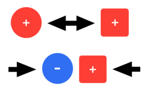
To understand electrophotography, we must first understand some basic electrostatic principles. When certain materials come in contact then separate from each other, these materials can become electrically charged. Rubbing these materials together can increase this effect. This is called the triboelectric effect. Static electricity buildup on your clothes in a dryer or from rubbing a balloon on your hair are examples of the triboelectric effect. Charges can have either a positive or negative polarity. Like charges repel each other while opposite charges are attracted, in much the same way as the polarities in magnets (see Figure 6.2).
These properties are at the core of the technology and are utilized in almost every stage of the digital imaging process.
Toner Basics
Toner is a very fine, dry powder medium used in the electrophotographic or xerographic process. It is composed primarily of a resin and includes pigment, wax, and process-enhancing additives. The term xerography, in fact, is derived from the Greek words xeros, ‘dry’ and graphia, ‘writing,’ reflecting how toner rather than ink is used in the imaging process. Toner particles become electrically charged when stirred or agitated through a triboelectric effect. The composition of the toner not only contributes to its imaging characteristics but to its ability to maintain and control its charge properties. The shape of the toner also is a factor in its charging capability. This electrical charge is what allows the toner to be precisely manipulated throughout the process.
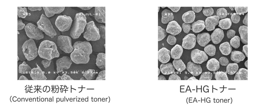
There are two basic types of toner production, pulverized and chemical (Figure 6.3). Pulverized toner was commonly used in earlier digital printers and is manufactured by successive compound mixing and grinding steps until the desired consistency and size is achieved. The resulting toner particles are irregular in size and shape and typically average around 6.2 to 10.2 microns in size. Pulverized toner produces good results, up to 600 dpi resolution; however, a consistent size and shape along with a smaller particle size is required to produce better clarity and detail at higher resolutions.

Chemical toners were introduced later to overcome those limitations and are in common use today. Each manufacturer has its own process for creating this type of toner and unique names as well. Xerox’s EA toner, Ricoh’s PxP toner, and Konica Minolta’s Simitri toner are all examples of chemical toners. As the name suggests, chemical toners are created through a process of building or ‘growing’ the particle chemically. This process allows for the precise control of the shape and size of the toner particle (under 5 microns in some cases), resulting in higher definition and resolution capabilities. Resolutions of 1,200 dpi and 2,400 dpi are possible largely due to the use of this type of toner. Other benefits include much lower energy consumption, both in the manufacturing process and printing process, as well as narrower particle size and charge distributions.
Here is a YouTube video of how chemical toner is made: https://youtu.be/852TWDP61T4
Dry toner comes in two forms: mono component and dual component. Both rely on magnetic iron or iron oxide particles to ‘hold’ the charged toner on a magnetic roller. Mono component toners incorporate the magnetic material in the composition of the toner particle itself where dual component toners have the magnetic material mixed together with the toner but as separate components. This mixture is called developer.
ElectroInk
ElectroInk is a unique form of toner used in HP Indigo digital presses. The toner comes in the form of a paste and is mixed internally in the press with imaging oil, a lightweight petroleum distillate. This type of toner is considered a liquid toner as the particles are suspended in the liquid imaging oil, but still uses an electrophotographic process for imaging. One of the important advantages of this type of toner is its particle size. ElectroInk toner particles are 1 to 2 microns, significantly smaller than the smallest dry toner particle. At this size, a dry toner would become airborne and would be very difficult to control. The toner and oil suspension achieves higher resolutions, uniform gloss, sharp image edges, and very thin image layers. A thin image layer allows the toner to conform to the surface of the substrate, producing a consistent look between imaged and non-imaged areas. A drawback of this toner, however, is that substrates may need to be pre-treated in order for the toner to adhere properly. There are substrates available for use specifically on HP Indigo digital presses, but typically these are more expensive or may not be compatible with other printing methods. Some Indigo presses are equipped with a pre-treating station that expands substrate compatibility extensively and even surpasses that of other forms of digital printing.
Nanography
Nanography is a very new and exciting print technology currently in development by the creator of the Indigo digital press, Benny Landa. It borrows some of the same concepts used in the Indigo but with a different approach to the implementation of these. The technology centres around NanoInk, a breakthrough ink with pigment sizes in the tens of nanometers. In comparison, pigments found in good-quality offset inks are in the 500 nanometre range. Colorants intensify and ink density increases at this microscopic level, thereby expanding the ink’s colour gamut considerably. The ink uses water as a carrier instead of imaging oil making it more cost effective and eco-friendly. Billions of ink droplets are jetted onto a heated blanket, not directly onto the substrate as in inkjet printing. The ink spreads uniformly on the blanket and the water quickly evaporates leaving only an ultra-thin (approximately 500 nanometres), dry polymeric film. This film transfers completely onto the substrate on contact and produces a tough, abrasion-resistant image. This print technology can be used with almost any substrate without pre-treatment and, due to its minuscule film thickness, does not interfere with the finish. Whether high gloss or matte, the ink finish matches that of the substrate. Although the technology is poised to revolutionize the print industry, the first press to use it is currently in beta testing. You can find the latest news and more information on nanography on this webpage: http://www.landanano.com/nanography
Media Attributions
- Electrostatic principles by Roberto Medeiros
- EA-HG_toner by Fuji Xerox Co., Ltd


