
16: Chapter 16. Add/edit elevation, section, detail, text, annotation, and rooms
- Page ID
- 13198

\( \newcommand{\vecs}[1]{\overset { \scriptstyle \rightharpoonup} {\mathbf{#1}} } \)
\( \newcommand{\vecd}[1]{\overset{-\!-\!\rightharpoonup}{\vphantom{a}\smash {#1}}} \)
\( \newcommand{\dsum}{\displaystyle\sum\limits} \)
\( \newcommand{\dint}{\displaystyle\int\limits} \)
\( \newcommand{\dlim}{\displaystyle\lim\limits} \)
\( \newcommand{\id}{\mathrm{id}}\) \( \newcommand{\Span}{\mathrm{span}}\)
( \newcommand{\kernel}{\mathrm{null}\,}\) \( \newcommand{\range}{\mathrm{range}\,}\)
\( \newcommand{\RealPart}{\mathrm{Re}}\) \( \newcommand{\ImaginaryPart}{\mathrm{Im}}\)
\( \newcommand{\Argument}{\mathrm{Arg}}\) \( \newcommand{\norm}[1]{\| #1 \|}\)
\( \newcommand{\inner}[2]{\langle #1, #2 \rangle}\)
\( \newcommand{\Span}{\mathrm{span}}\)
\( \newcommand{\id}{\mathrm{id}}\)
\( \newcommand{\Span}{\mathrm{span}}\)
\( \newcommand{\kernel}{\mathrm{null}\,}\)
\( \newcommand{\range}{\mathrm{range}\,}\)
\( \newcommand{\RealPart}{\mathrm{Re}}\)
\( \newcommand{\ImaginaryPart}{\mathrm{Im}}\)
\( \newcommand{\Argument}{\mathrm{Arg}}\)
\( \newcommand{\norm}[1]{\| #1 \|}\)
\( \newcommand{\inner}[2]{\langle #1, #2 \rangle}\)
\( \newcommand{\Span}{\mathrm{span}}\) \( \newcommand{\AA}{\unicode[.8,0]{x212B}}\)
\( \newcommand{\vectorA}[1]{\vec{#1}} % arrow\)
\( \newcommand{\vectorAt}[1]{\vec{\text{#1}}} % arrow\)
\( \newcommand{\vectorB}[1]{\overset { \scriptstyle \rightharpoonup} {\mathbf{#1}} } \)
\( \newcommand{\vectorC}[1]{\textbf{#1}} \)
\( \newcommand{\vectorD}[1]{\overrightarrow{#1}} \)
\( \newcommand{\vectorDt}[1]{\overrightarrow{\text{#1}}} \)
\( \newcommand{\vectE}[1]{\overset{-\!-\!\rightharpoonup}{\vphantom{a}\smash{\mathbf {#1}}}} \)
\( \newcommand{\vecs}[1]{\overset { \scriptstyle \rightharpoonup} {\mathbf{#1}} } \)
\(\newcommand{\longvect}{\overrightarrow}\)
\( \newcommand{\vecd}[1]{\overset{-\!-\!\rightharpoonup}{\vphantom{a}\smash {#1}}} \)
\(\newcommand{\avec}{\mathbf a}\) \(\newcommand{\bvec}{\mathbf b}\) \(\newcommand{\cvec}{\mathbf c}\) \(\newcommand{\dvec}{\mathbf d}\) \(\newcommand{\dtil}{\widetilde{\mathbf d}}\) \(\newcommand{\evec}{\mathbf e}\) \(\newcommand{\fvec}{\mathbf f}\) \(\newcommand{\nvec}{\mathbf n}\) \(\newcommand{\pvec}{\mathbf p}\) \(\newcommand{\qvec}{\mathbf q}\) \(\newcommand{\svec}{\mathbf s}\) \(\newcommand{\tvec}{\mathbf t}\) \(\newcommand{\uvec}{\mathbf u}\) \(\newcommand{\vvec}{\mathbf v}\) \(\newcommand{\wvec}{\mathbf w}\) \(\newcommand{\xvec}{\mathbf x}\) \(\newcommand{\yvec}{\mathbf y}\) \(\newcommand{\zvec}{\mathbf z}\) \(\newcommand{\rvec}{\mathbf r}\) \(\newcommand{\mvec}{\mathbf m}\) \(\newcommand{\zerovec}{\mathbf 0}\) \(\newcommand{\onevec}{\mathbf 1}\) \(\newcommand{\real}{\mathbb R}\) \(\newcommand{\twovec}[2]{\left[\begin{array}{r}#1 \\ #2 \end{array}\right]}\) \(\newcommand{\ctwovec}[2]{\left[\begin{array}{c}#1 \\ #2 \end{array}\right]}\) \(\newcommand{\threevec}[3]{\left[\begin{array}{r}#1 \\ #2 \\ #3 \end{array}\right]}\) \(\newcommand{\cthreevec}[3]{\left[\begin{array}{c}#1 \\ #2 \\ #3 \end{array}\right]}\) \(\newcommand{\fourvec}[4]{\left[\begin{array}{r}#1 \\ #2 \\ #3 \\ #4 \end{array}\right]}\) \(\newcommand{\cfourvec}[4]{\left[\begin{array}{c}#1 \\ #2 \\ #3 \\ #4 \end{array}\right]}\) \(\newcommand{\fivevec}[5]{\left[\begin{array}{r}#1 \\ #2 \\ #3 \\ #4 \\ #5 \\ \end{array}\right]}\) \(\newcommand{\cfivevec}[5]{\left[\begin{array}{c}#1 \\ #2 \\ #3 \\ #4 \\ #5 \\ \end{array}\right]}\) \(\newcommand{\mattwo}[4]{\left[\begin{array}{rr}#1 \amp #2 \\ #3 \amp #4 \\ \end{array}\right]}\) \(\newcommand{\laspan}[1]{\text{Span}\{#1\}}\) \(\newcommand{\bcal}{\cal B}\) \(\newcommand{\ccal}{\cal C}\) \(\newcommand{\scal}{\cal S}\) \(\newcommand{\wcal}{\cal W}\) \(\newcommand{\ecal}{\cal E}\) \(\newcommand{\coords}[2]{\left\{#1\right\}_{#2}}\) \(\newcommand{\gray}[1]{\color{gray}{#1}}\) \(\newcommand{\lgray}[1]{\color{lightgray}{#1}}\) \(\newcommand{\rank}{\operatorname{rank}}\) \(\newcommand{\row}{\text{Row}}\) \(\newcommand{\col}{\text{Col}}\) \(\renewcommand{\row}{\text{Row}}\) \(\newcommand{\nul}{\text{Nul}}\) \(\newcommand{\var}{\text{Var}}\) \(\newcommand{\corr}{\text{corr}}\) \(\newcommand{\len}[1]{\left|#1\right|}\) \(\newcommand{\bbar}{\overline{\bvec}}\) \(\newcommand{\bhat}{\widehat{\bvec}}\) \(\newcommand{\bperp}{\bvec^\perp}\) \(\newcommand{\xhat}{\widehat{\xvec}}\) \(\newcommand{\vhat}{\widehat{\vvec}}\) \(\newcommand{\uhat}{\widehat{\uvec}}\) \(\newcommand{\what}{\widehat{\wvec}}\) \(\newcommand{\Sighat}{\widehat{\Sigma}}\) \(\newcommand{\lt}{<}\) \(\newcommand{\gt}{>}\) \(\newcommand{\amp}{&}\) \(\definecolor{fillinmathshade}{gray}{0.9}\) Session Objectives
Upon completing this session, students will be able to:
(CO 1) Add/Edit Elevations & Sections – Adjust crop region
(CO 2) Add/Edit Detail views
(CO 3) Add Texts & Annotations
(CO 4) Add/Edit Rooms, Room tags, Room separators
(CO 5) Add/Edit a color fill scheme
 Session Highlights
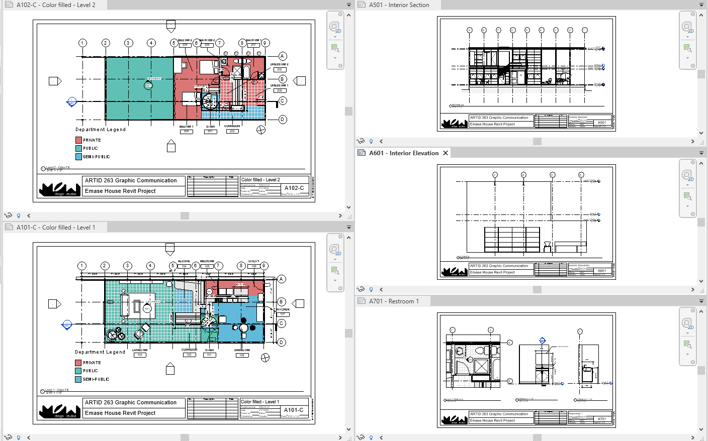
At the end of the session, students can create the graphics below.
 Lecture Contents
(CO 1) Add/Edit Elevations & Sections – Adjust crop region

A YouTube element has been excluded from this version of the text. You can view it online here: https://iastate.pressbooks.pub/visualgraphiccomm/?p=104
You can create sections or elevations in any floor plans.
To add an interior elevation
- [STEP 1] Open the project, and open [Level 1] floor plan
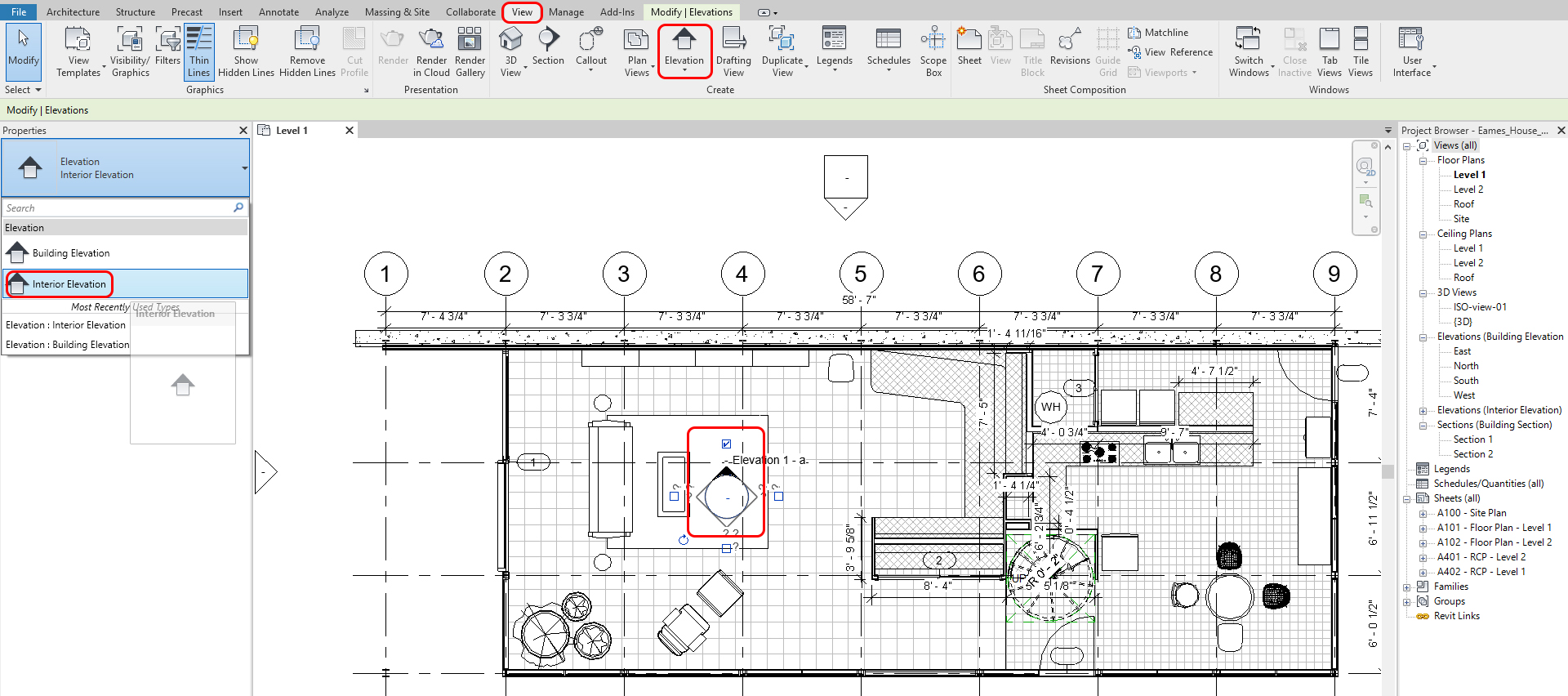
- [STEP 2] Click [Elevation] from [View] tab, under [Create] panel
- [STEP 3] Click the [Properties] palette > select Interior Elevation, the symbol will be updated.
- [STEP 4] Hover over your plan. You will notice the elevation marker will “snap” parallel to walls. Please select the location where you want to place your elevation and click to set it in place. Press [Esc] to complete the command
- [STEP 5] Select the elevation tag. You can create additional elevations from one elevation symbol. Press [Esc] to complete the command
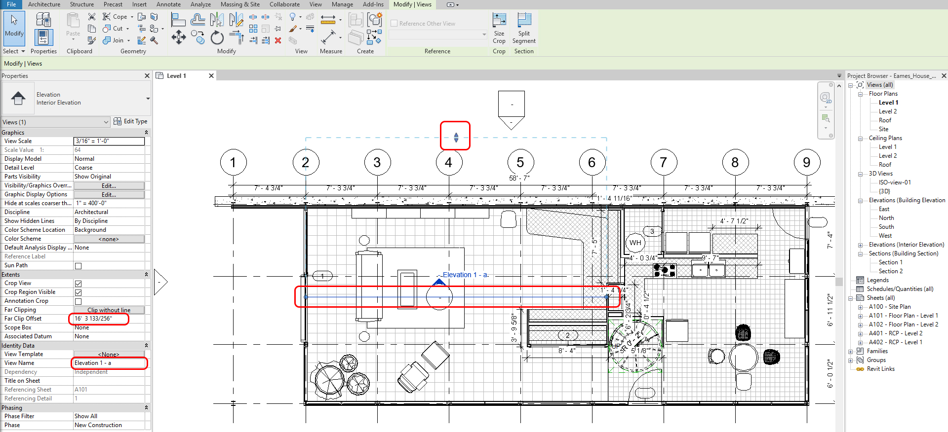
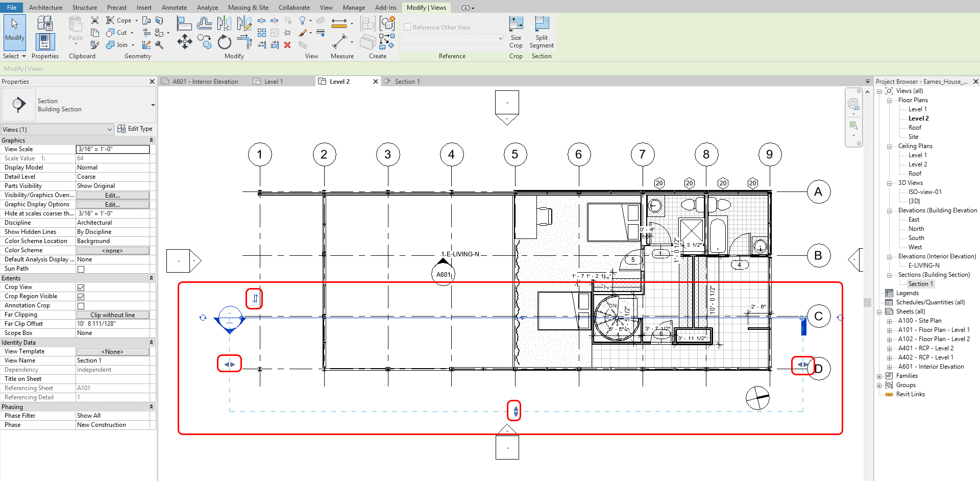
- [STEP 6] Select the elevation arrow (black filled) to adjust the crop region and view depth by moving the blue line; you can adjust where the elevation view begins. By adjusting the blue nodes on the line, you can define the crop region. Moreover, by moving the arrows, you can adjust the view depth of the elevation.
- [STEP 7] Once your elevation is defined, double click on the arrow of the elevation symbol > the newly created elevation view will be open. You may realize the current view is not what you want to present. If the view shows right, please skip [STEP 8] and [STEP 9]
- [STEP 8]Click the edge of the elevation > click [Edit Crop]
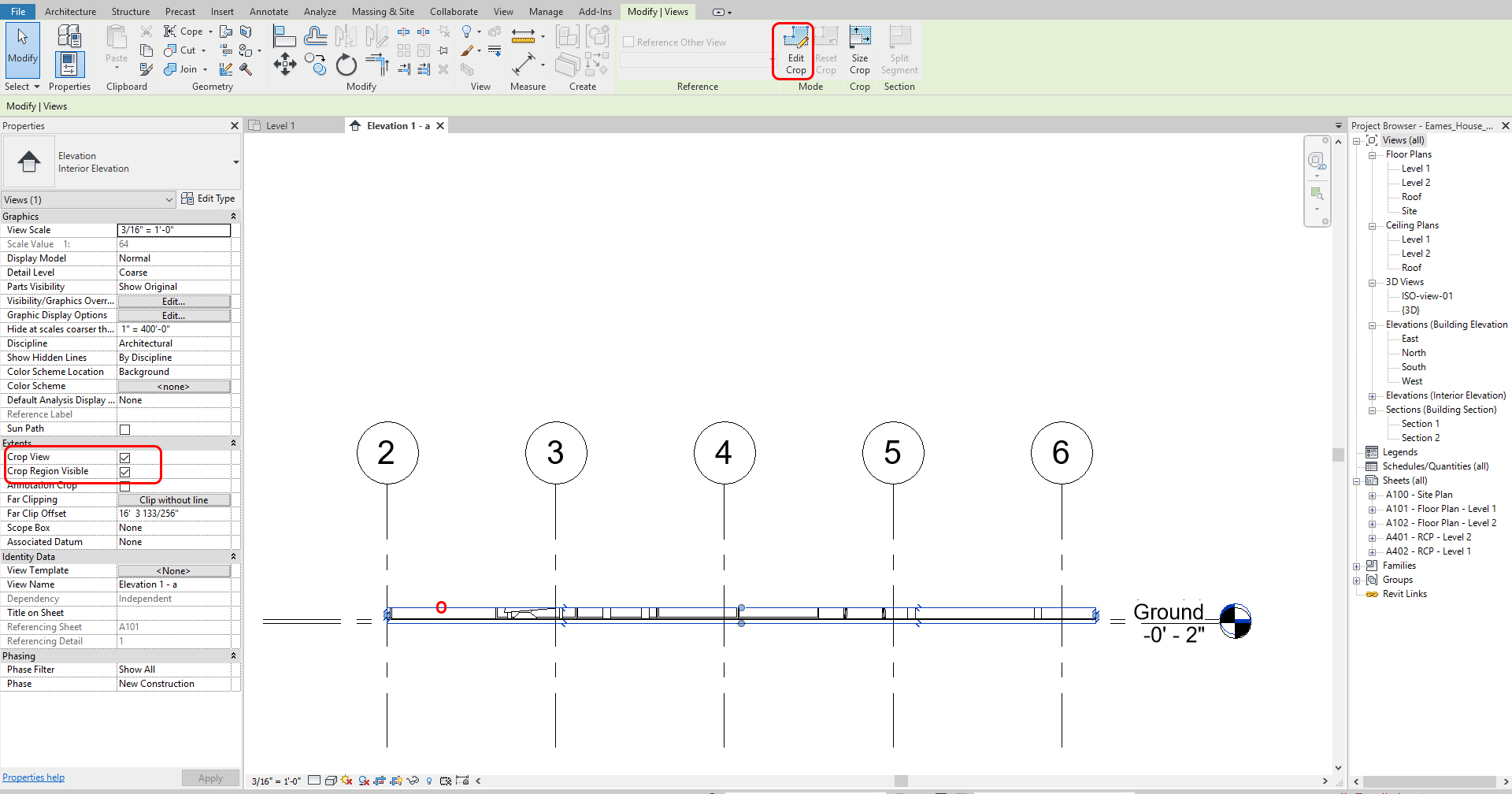
- [STEP 9] Redraw the boundary of the elevation. The boundary must be a closed-loop > Click [Green check-mark] to finish the crop boundary.
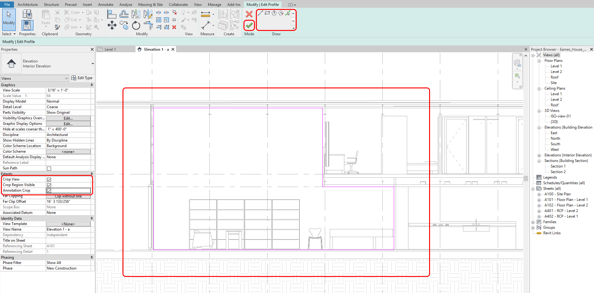
- [STEP 10] Make sure you check all three [Crop view], [Crop Region Visible], and [Annotation Crop] on [Properties] palette.
Note. The solid blue defines the visible region, and the dashed line defines where your annotations can be viewed and placed. Additionally, you can continue to adjust their view ranges by clicking on the nodes.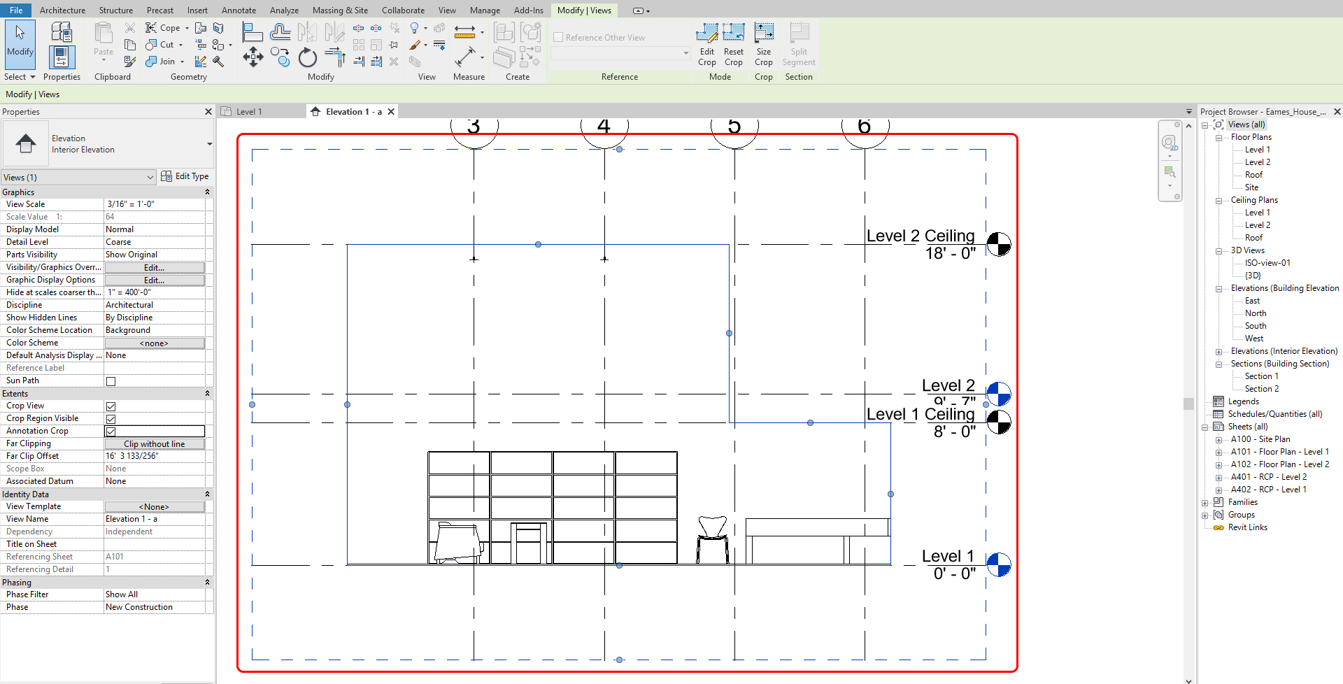
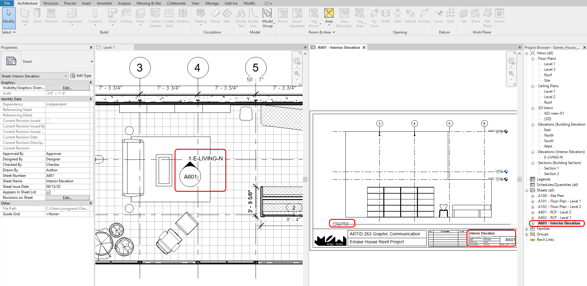
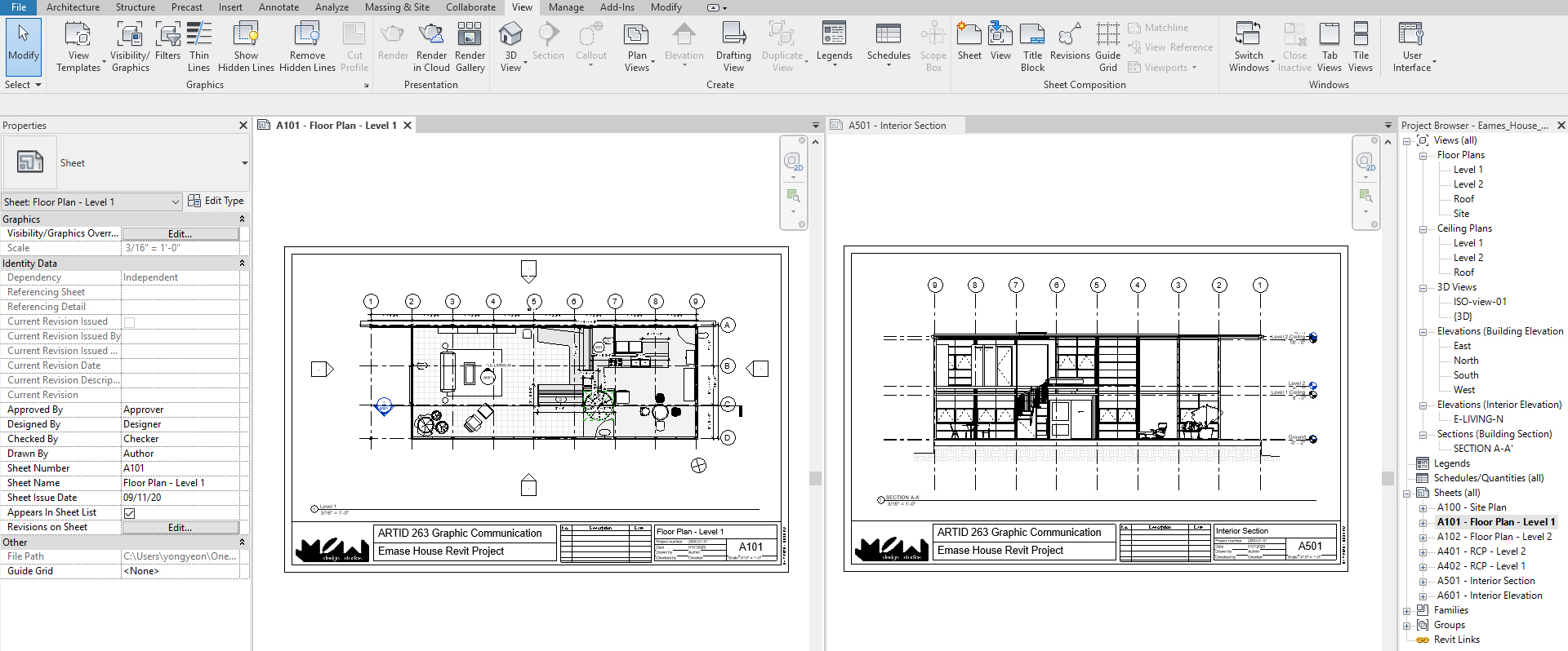
- [STEP 11] Add a sheet for the elevation by mouse right-clicking and clicking [New Sheet] on Sheets(all) from [Project Browser] > Select 11×17 titleblock page that you created > Rename the sheet – Sheet number [A601], Sheet name – Interior Elevation > Once the empty sheet is open > Drag the elevation view from [Project Browser] to the sheet > Rename the view title [E-LIVING-N] > Then you can see the elevation symbol name and view name updated on the floor plan
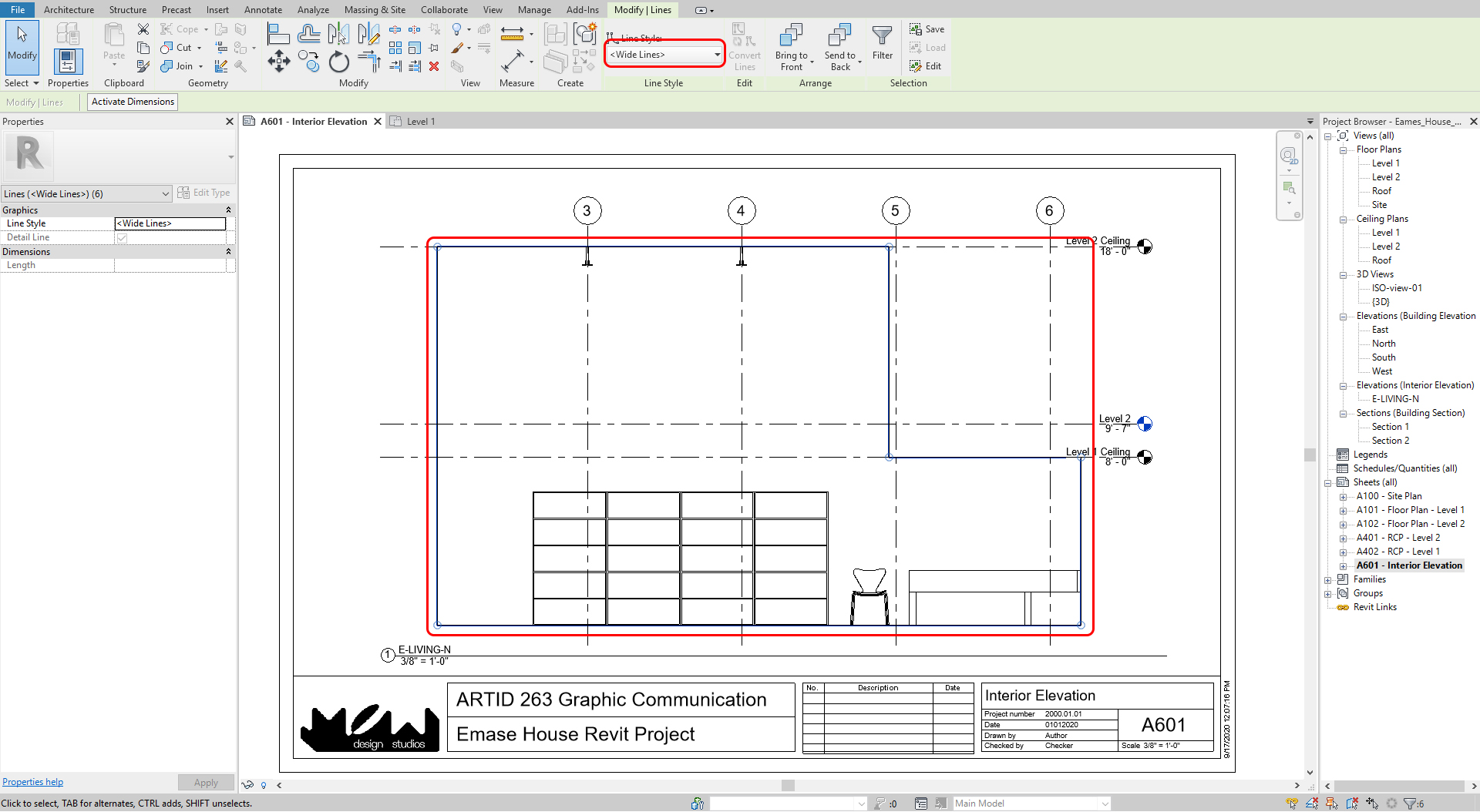
- [STEP 12] Usually, we want to show the boundary of elevation in a bold line. On your sheet, add [Detail Line] from [Annotation] tab, under [Detail] panel, or type [DL] > Select [Wide Lines] from [Modify] tab, under [Line Styles] > Trace the boundary lines
To add a section view
- [STEP 1] You will use similar steps to create section views
- [STEP 2] Click [Section] from [View] tab, under [Create] panel
- [STEP 3] Draw a section line by clicking two points, then you can change the view direction and boundary of the view
- [STEP 4] Set a sheet for the section
(CO 2) Add/Edit Detail views
A YouTube element has been excluded from this version of the text. You can view it online here: https://iastate.pressbooks.pub/visualgraphiccomm/?p=104
Add detailed views
- [STEP 1] Click [Callout] from [View] tab, under [Create] panel
- [STEP 2] Draw the boundary of a view on your floor plan > then [Level 2-Callout] will be automatically created under [Floor plans] > Rename the view to [Level 2 – Restrooms] > If needed, update the scale
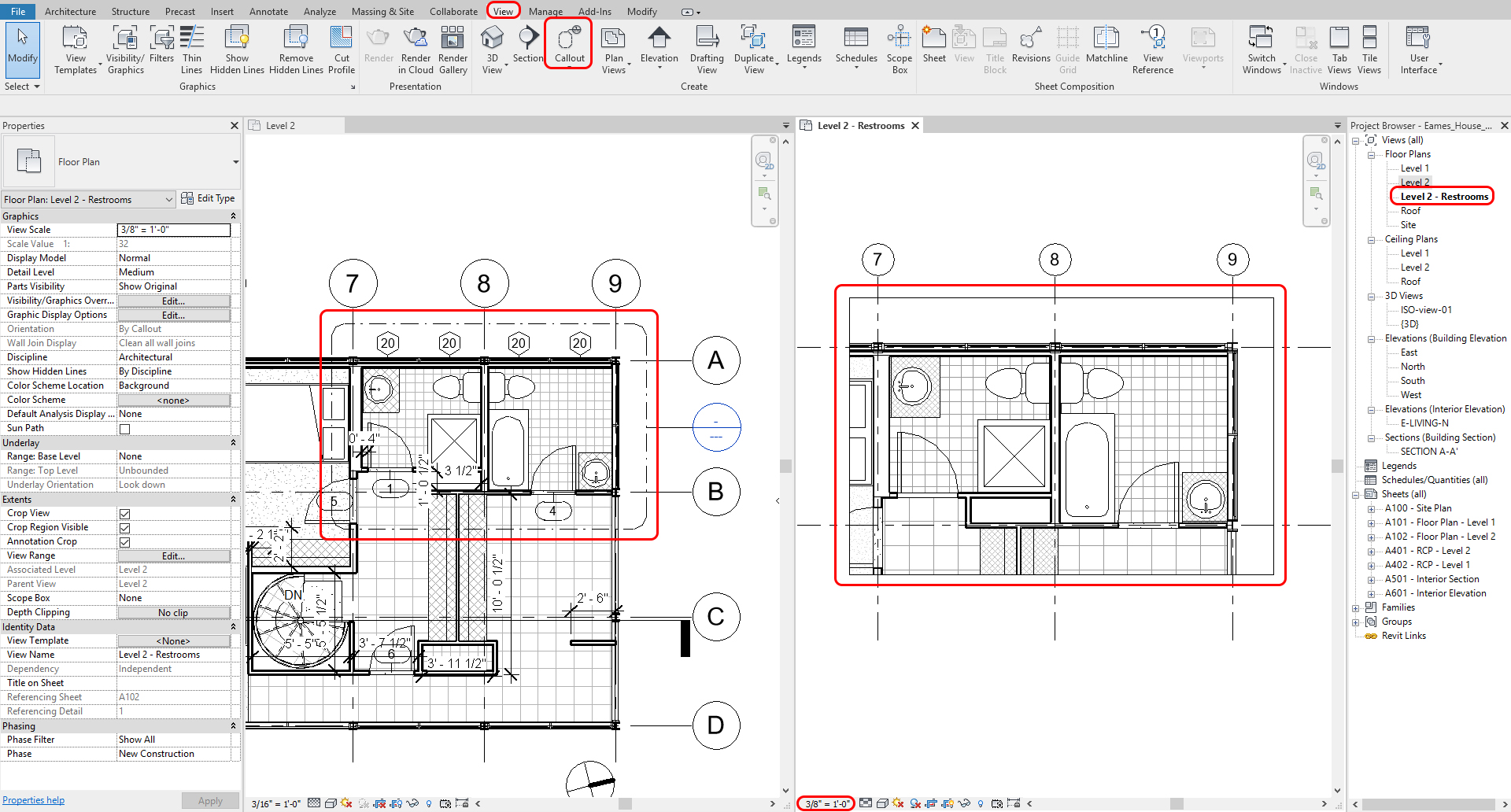
- [STEP 3] Create an elevation view and a section view on the detail view > add details > Update scales > Hide [elevation symbol] on [Level 2] floor plan > Hide [Section symbol] on [Level 2 – Restrooms] detail view and [Level 2] floor plan
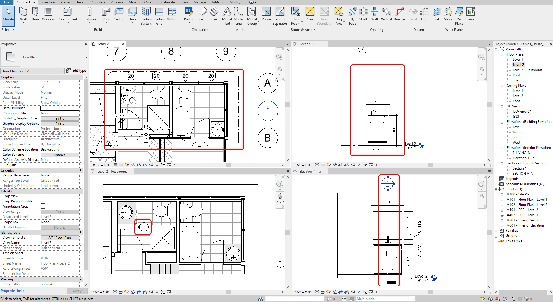
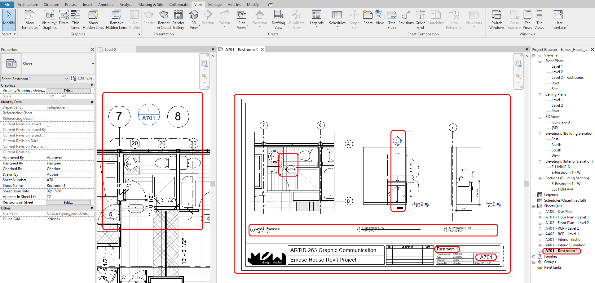
- [STEP 4] Add the detail views to the sheet [A701-Restroom 1]
(CO 3) Add Texts & Annotations

A YouTube element has been excluded from this version of the text. You can view it online here: https://iastate.pressbooks.pub/visualgraphiccomm/?p=104
Annotation (Texts, Notes, and Dimensions) can be added to any views and sheets
In this tutorial, you will practice the [TEXT] tool to add texts and notes
- [STEP 1] Open a [view] from [sheet] by double-clicking the view > On the view, click [Text] from [Annotate] tab, under [Text] panel > Select a text type from [Properties] panel > Drag and drop to make a text box > Add text
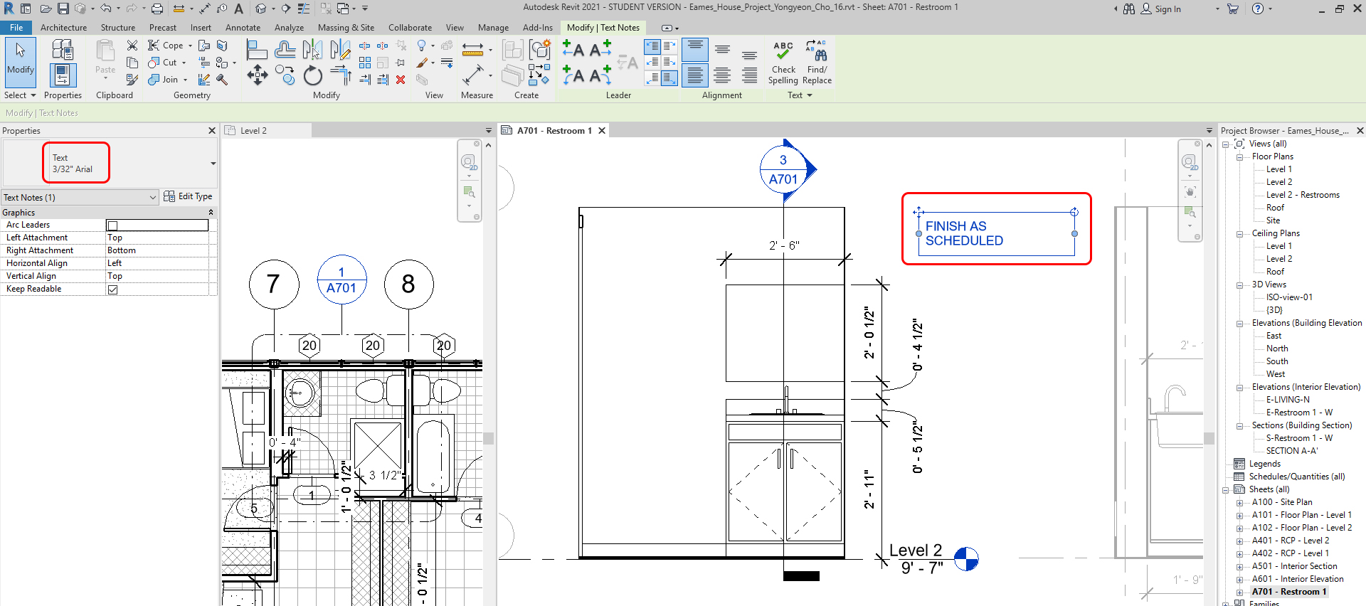
Note. If you need a different style of text type, you can duplicate the type and edit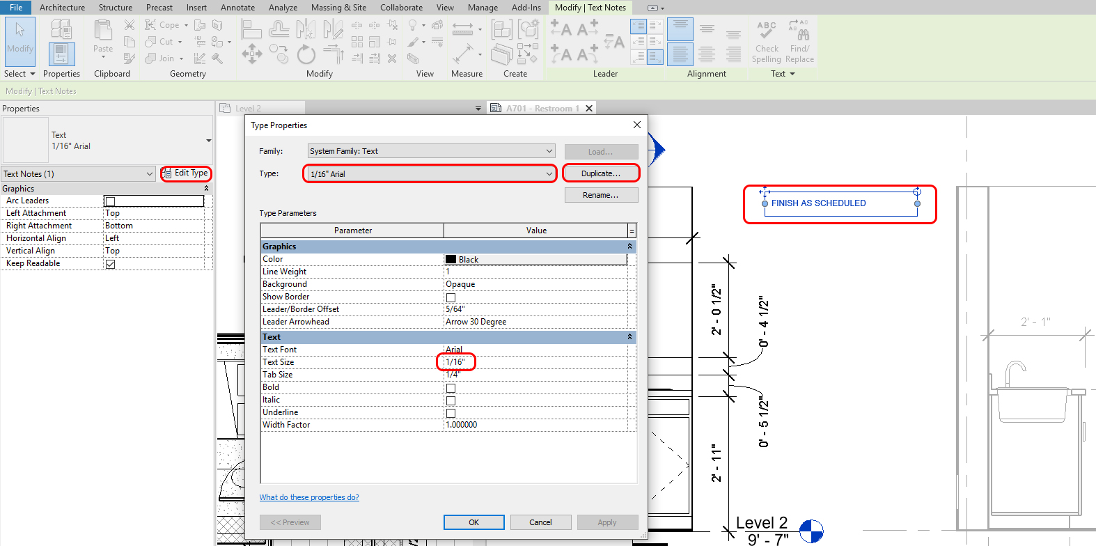
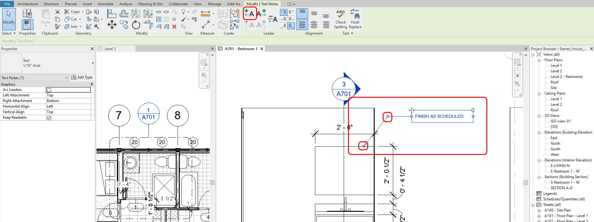
- [STEP 2] Add a leader line(s) by clicking the [Leader] icon from the [Modify] tab > adjust arrow direction and the leader line
(CO 4) Add/Edit Rooms, Room tags, Room separators
A YouTube element has been excluded from this version of the text. You can view it online here: https://iastate.pressbooks.pub/visualgraphiccomm/?p=104
Another useful annotation tool is creating, defining, and tagging rooms in Revit. Once you have walls, Revit recognizes the walls as the boundary of the rooms. However, if you have unclear boundaries, you have to define room boundary by using [Room Separator] first
Confirm room boundaries
- [STEP 1] Click [Room] from [Architecture] tab, under [Room & Area] panel
- [STEP 2] Hover the mouse over the floor plan to find a closed room. You can confirm the boundaries by clicking [Highlight Boundaries]
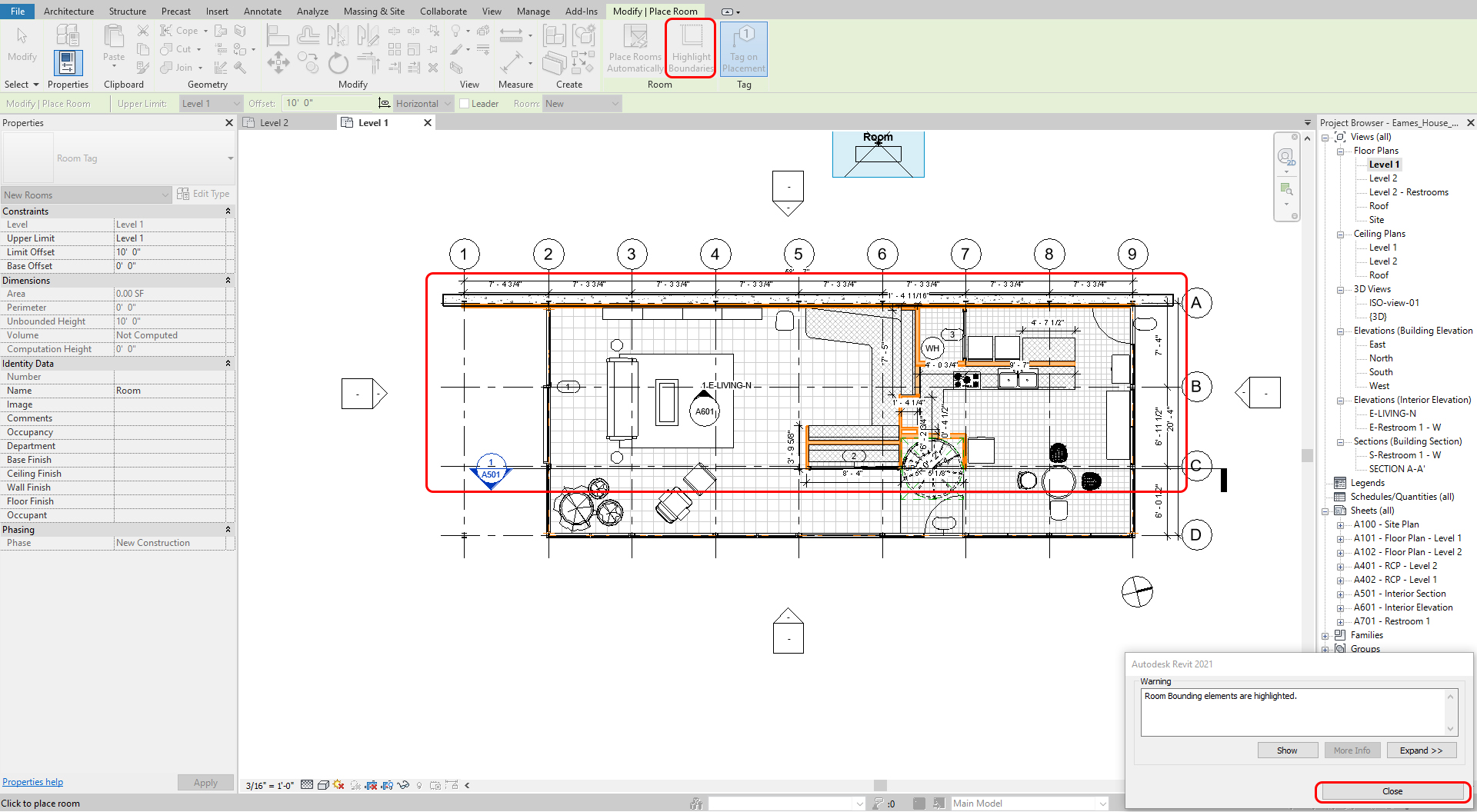
- [STEP 3] Click [Close] to hide the highlighted boundaries
Define boundaries
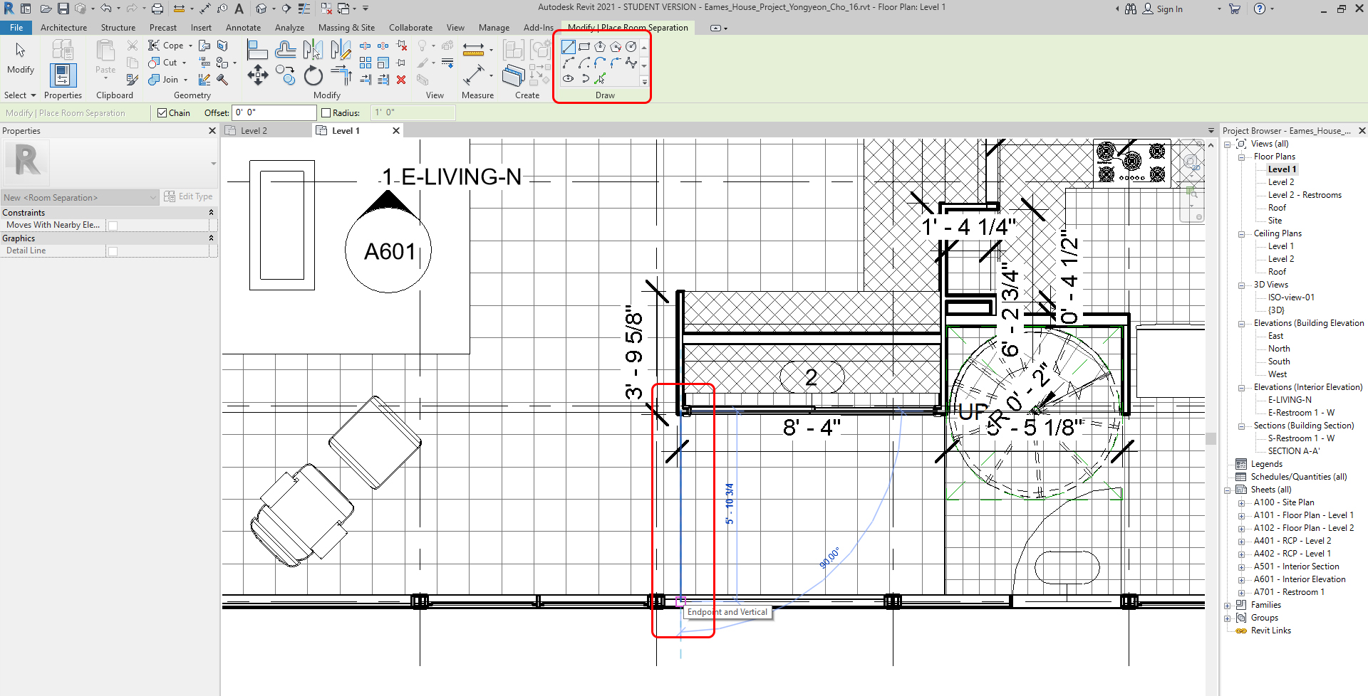
- [STEP 1] To define boundaries, click [Room Separator] from [Architecture] tab, under [Room & Area] panel
- [STEP 2] Using [Draw] tool to draw separated boundaries, then you can manually define boundaries.
Create rooms
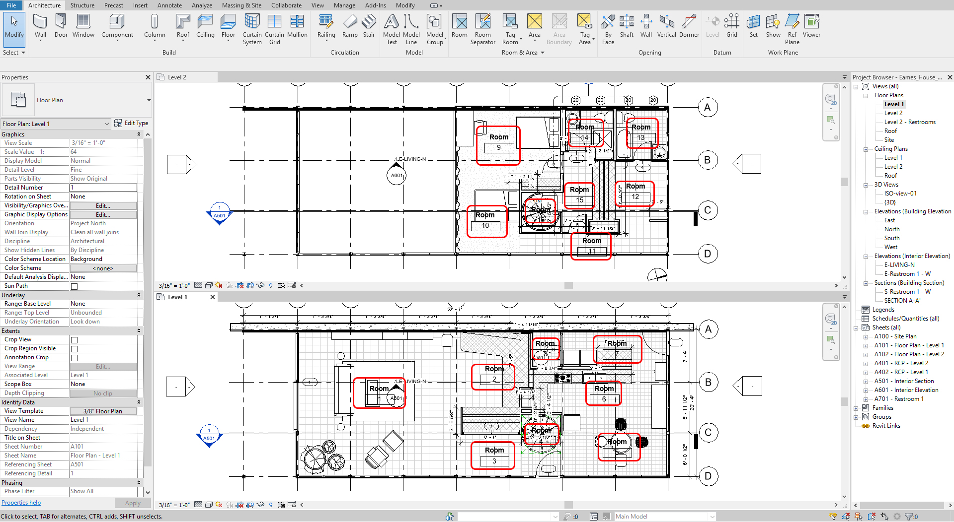
- [STEP 1] Click [Room] from [Architecture] tab, under [Room & Area] panel
- [STEP 2] Hover over each room and click once with the mouse to define the room boundary. You will see a tag that reads [ROOM] and a [X] showing the extent of the room. Continue for each room.
Edit tags
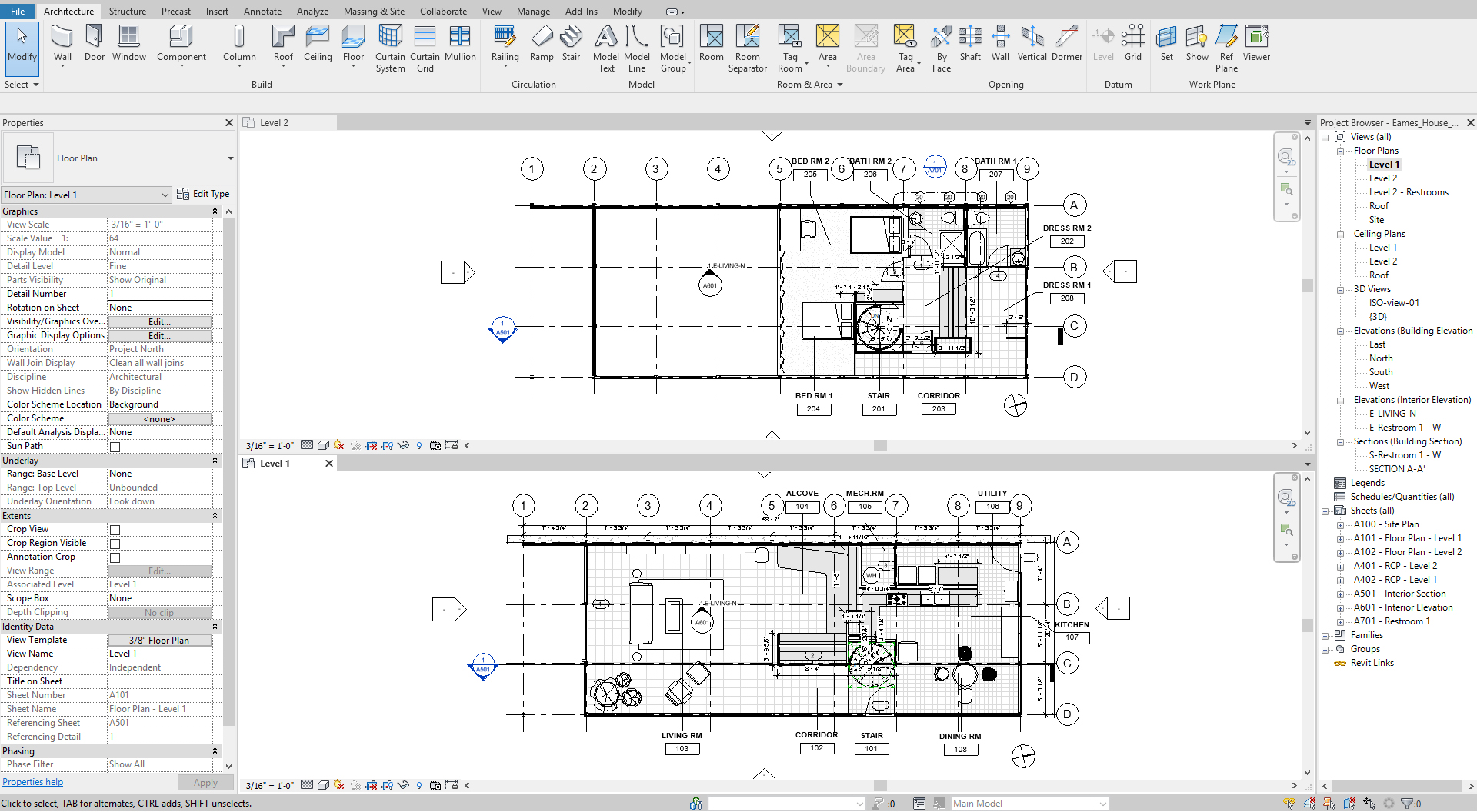
- [STEP 1] Click a room tag (NAME) two times, then you can edit the room name. Click a room tag (NUMBER) two times. Then you can edit the room number.
Note. If the rooms are located on the 1st floor, the number starts from 101. If the rooms are located on the 2nd floor, the number starts from 201. - [STEP 2] Move the room tags outside of the room to avoid overlapping with model lines and the room names > Select all room tags > Check [Leader Line] box > Move the room tags to the outside of the room
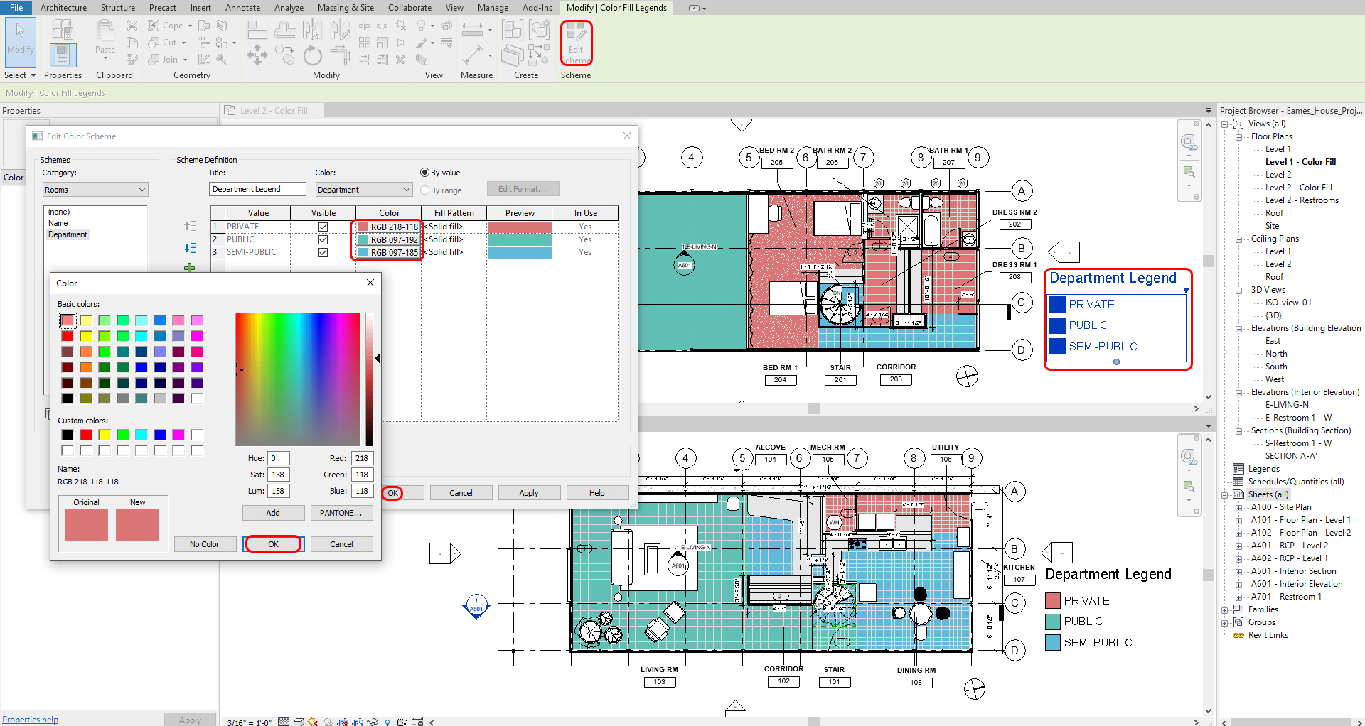
(CO 5) Add/Edit a color fill scheme
A YouTube element has been excluded from this version of the text. You can view it online here: https://iastate.pressbooks.pub/visualgraphiccomm/?p=104
You can use the [color fill legend] to place rooms and spaces after adding rooms. Color coding plans can help the client understand the relationship between public and private, work, and rest spaces.
Add a color fill legend
- [STEP 1] Click a [room] on a floor plan > Add [PUBLIC], [SEMI-PRIVATE], or [PRIVATE] on [Department] from [Properties] palette > If you already added one of the three options, you can select from the drop-down menu.
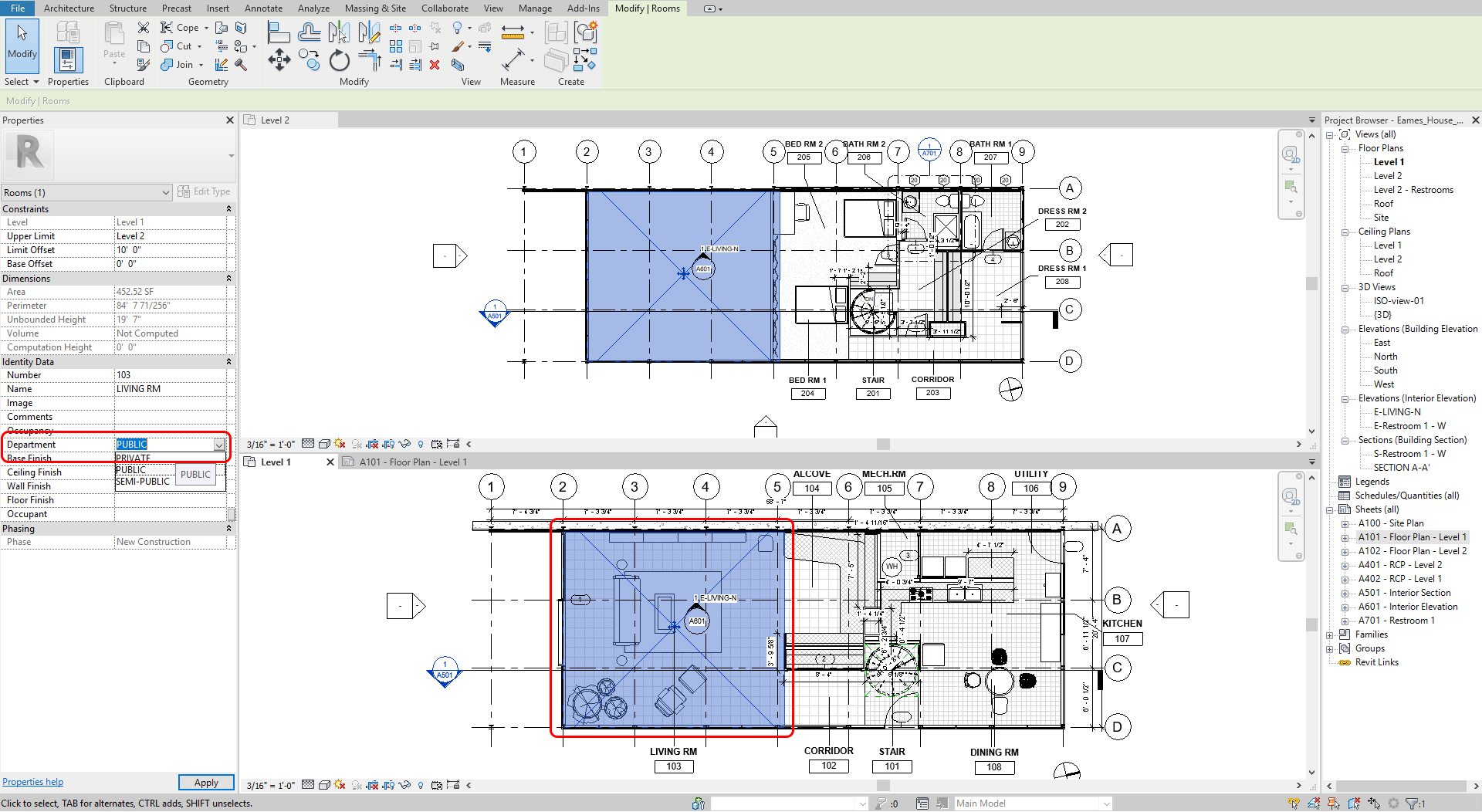
- [STEP 2] Repeat step 1 for all rooms
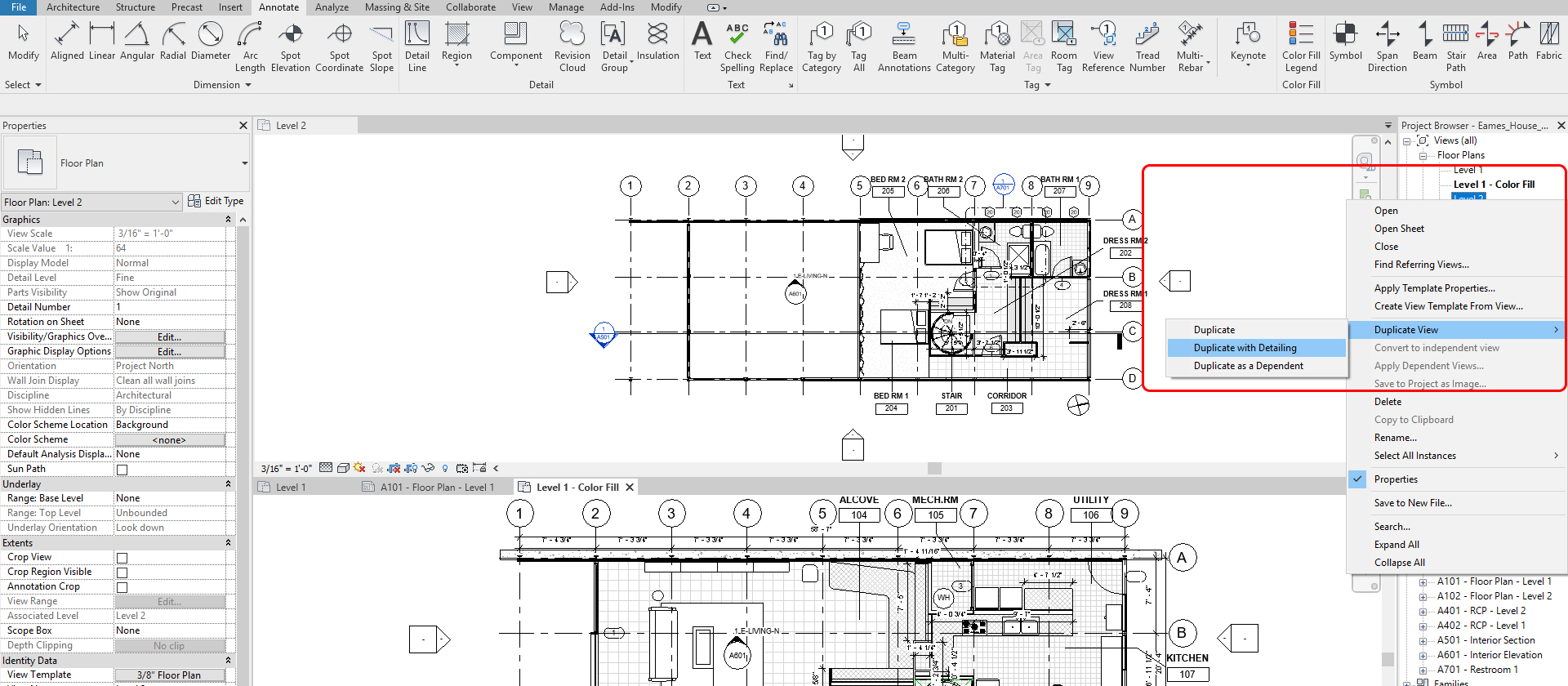
- [STEP 3] Duplicate floor plans for only the color-filled plans by right-clicking a view > select [Duplicate view] > select [Duplicate with Detailing] > Rename the copied views
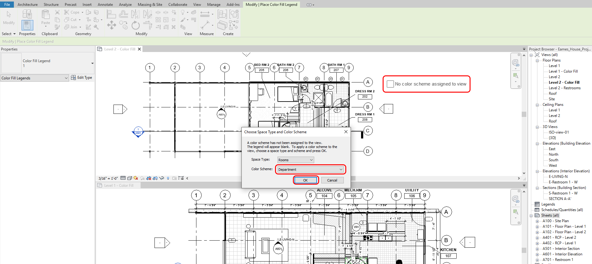
- [STEP 4] Open the duplicated views > Click [Color Fill Legend] from [Annotate] tab, under [Color Fill] panel > Click on a floor plan, then [Choose Space Type and Color Scheme] window will open > Confirm Space type: Room, Color Scheme: Department > Click [OK] then the color-filled legend and color will show.
- [STEP 5] Repeat this step 4 for another plan
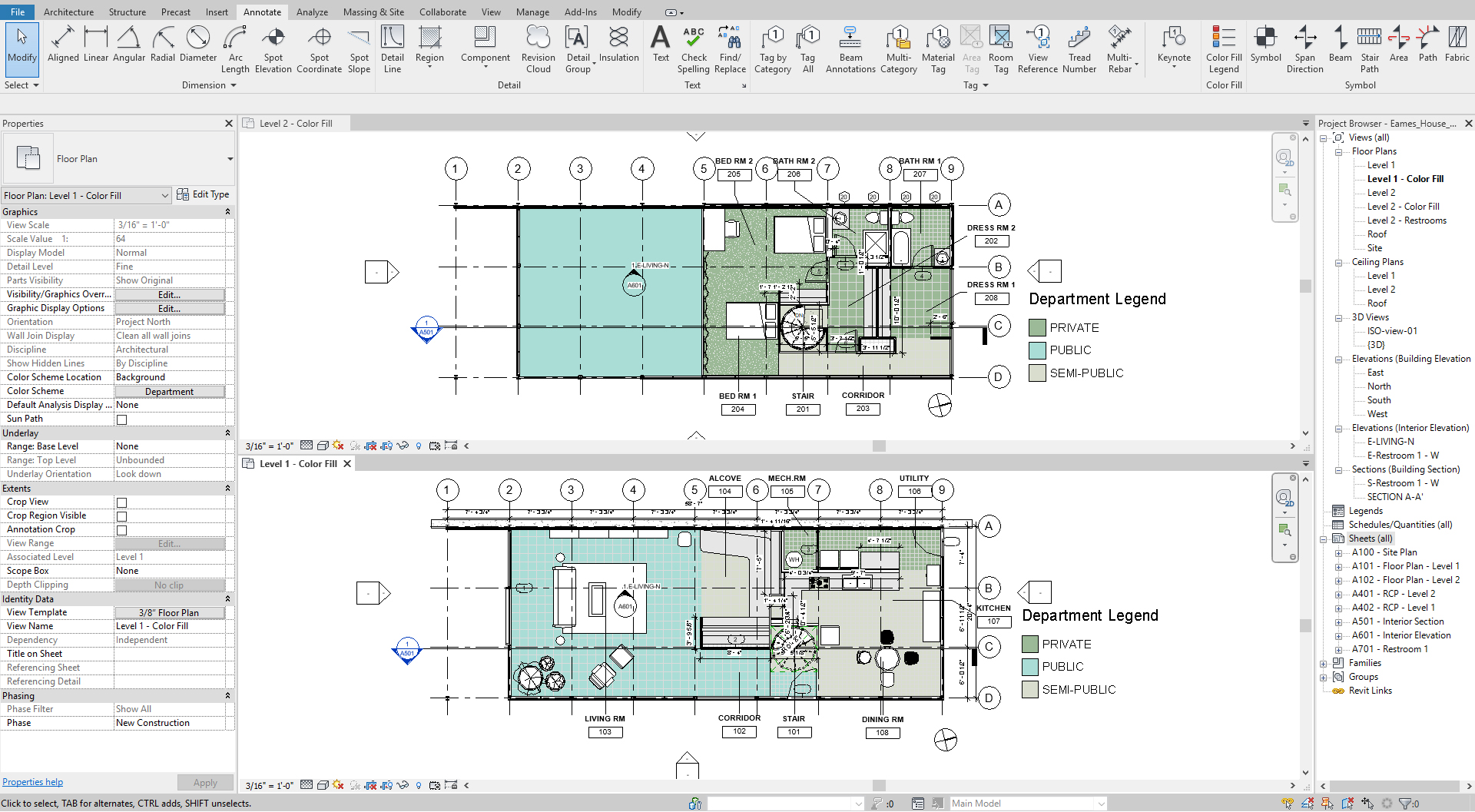
- [STEP 6] To update color, Click the legend > click [Edit Scheme] > Define color> Click [OK] to finish color scheme
SAVE the file before closing the application.
Save in a different location for the backup (e.g., a cloud folder)