
2.4: Building representation in BIM
- Page ID
- 22992

\( \newcommand{\vecs}[1]{\overset { \scriptstyle \rightharpoonup} {\mathbf{#1}} } \)
\( \newcommand{\vecd}[1]{\overset{-\!-\!\rightharpoonup}{\vphantom{a}\smash {#1}}} \)
\( \newcommand{\id}{\mathrm{id}}\) \( \newcommand{\Span}{\mathrm{span}}\)
( \newcommand{\kernel}{\mathrm{null}\,}\) \( \newcommand{\range}{\mathrm{range}\,}\)
\( \newcommand{\RealPart}{\mathrm{Re}}\) \( \newcommand{\ImaginaryPart}{\mathrm{Im}}\)
\( \newcommand{\Argument}{\mathrm{Arg}}\) \( \newcommand{\norm}[1]{\| #1 \|}\)
\( \newcommand{\inner}[2]{\langle #1, #2 \rangle}\)
\( \newcommand{\Span}{\mathrm{span}}\)
\( \newcommand{\id}{\mathrm{id}}\)
\( \newcommand{\Span}{\mathrm{span}}\)
\( \newcommand{\kernel}{\mathrm{null}\,}\)
\( \newcommand{\range}{\mathrm{range}\,}\)
\( \newcommand{\RealPart}{\mathrm{Re}}\)
\( \newcommand{\ImaginaryPart}{\mathrm{Im}}\)
\( \newcommand{\Argument}{\mathrm{Arg}}\)
\( \newcommand{\norm}[1]{\| #1 \|}\)
\( \newcommand{\inner}[2]{\langle #1, #2 \rangle}\)
\( \newcommand{\Span}{\mathrm{span}}\) \( \newcommand{\AA}{\unicode[.8,0]{x212B}}\)
\( \newcommand{\vectorA}[1]{\vec{#1}} % arrow\)
\( \newcommand{\vectorAt}[1]{\vec{\text{#1}}} % arrow\)
\( \newcommand{\vectorB}[1]{\overset { \scriptstyle \rightharpoonup} {\mathbf{#1}} } \)
\( \newcommand{\vectorC}[1]{\textbf{#1}} \)
\( \newcommand{\vectorD}[1]{\overrightarrow{#1}} \)
\( \newcommand{\vectorDt}[1]{\overrightarrow{\text{#1}}} \)
\( \newcommand{\vectE}[1]{\overset{-\!-\!\rightharpoonup}{\vphantom{a}\smash{\mathbf {#1}}}} \)
\( \newcommand{\vecs}[1]{\overset { \scriptstyle \rightharpoonup} {\mathbf{#1}} } \)
\( \newcommand{\vecd}[1]{\overset{-\!-\!\rightharpoonup}{\vphantom{a}\smash {#1}}} \)
\(\newcommand{\avec}{\mathbf a}\) \(\newcommand{\bvec}{\mathbf b}\) \(\newcommand{\cvec}{\mathbf c}\) \(\newcommand{\dvec}{\mathbf d}\) \(\newcommand{\dtil}{\widetilde{\mathbf d}}\) \(\newcommand{\evec}{\mathbf e}\) \(\newcommand{\fvec}{\mathbf f}\) \(\newcommand{\nvec}{\mathbf n}\) \(\newcommand{\pvec}{\mathbf p}\) \(\newcommand{\qvec}{\mathbf q}\) \(\newcommand{\svec}{\mathbf s}\) \(\newcommand{\tvec}{\mathbf t}\) \(\newcommand{\uvec}{\mathbf u}\) \(\newcommand{\vvec}{\mathbf v}\) \(\newcommand{\wvec}{\mathbf w}\) \(\newcommand{\xvec}{\mathbf x}\) \(\newcommand{\yvec}{\mathbf y}\) \(\newcommand{\zvec}{\mathbf z}\) \(\newcommand{\rvec}{\mathbf r}\) \(\newcommand{\mvec}{\mathbf m}\) \(\newcommand{\zerovec}{\mathbf 0}\) \(\newcommand{\onevec}{\mathbf 1}\) \(\newcommand{\real}{\mathbb R}\) \(\newcommand{\twovec}[2]{\left[\begin{array}{r}#1 \\ #2 \end{array}\right]}\) \(\newcommand{\ctwovec}[2]{\left[\begin{array}{c}#1 \\ #2 \end{array}\right]}\) \(\newcommand{\threevec}[3]{\left[\begin{array}{r}#1 \\ #2 \\ #3 \end{array}\right]}\) \(\newcommand{\cthreevec}[3]{\left[\begin{array}{c}#1 \\ #2 \\ #3 \end{array}\right]}\) \(\newcommand{\fourvec}[4]{\left[\begin{array}{r}#1 \\ #2 \\ #3 \\ #4 \end{array}\right]}\) \(\newcommand{\cfourvec}[4]{\left[\begin{array}{c}#1 \\ #2 \\ #3 \\ #4 \end{array}\right]}\) \(\newcommand{\fivevec}[5]{\left[\begin{array}{r}#1 \\ #2 \\ #3 \\ #4 \\ #5 \\ \end{array}\right]}\) \(\newcommand{\cfivevec}[5]{\left[\begin{array}{c}#1 \\ #2 \\ #3 \\ #4 \\ #5 \\ \end{array}\right]}\) \(\newcommand{\mattwo}[4]{\left[\begin{array}{rr}#1 \amp #2 \\ #3 \amp #4 \\ \end{array}\right]}\) \(\newcommand{\laspan}[1]{\text{Span}\{#1\}}\) \(\newcommand{\bcal}{\cal B}\) \(\newcommand{\ccal}{\cal C}\) \(\newcommand{\scal}{\cal S}\) \(\newcommand{\wcal}{\cal W}\) \(\newcommand{\ecal}{\cal E}\) \(\newcommand{\coords}[2]{\left\{#1\right\}_{#2}}\) \(\newcommand{\gray}[1]{\color{gray}{#1}}\) \(\newcommand{\lgray}[1]{\color{lightgray}{#1}}\) \(\newcommand{\rank}{\operatorname{rank}}\) \(\newcommand{\row}{\text{Row}}\) \(\newcommand{\col}{\text{Col}}\) \(\renewcommand{\row}{\text{Row}}\) \(\newcommand{\nul}{\text{Nul}}\) \(\newcommand{\var}{\text{Var}}\) \(\newcommand{\corr}{\text{corr}}\) \(\newcommand{\len}[1]{\left|#1\right|}\) \(\newcommand{\bbar}{\overline{\bvec}}\) \(\newcommand{\bhat}{\widehat{\bvec}}\) \(\newcommand{\bperp}{\bvec^\perp}\) \(\newcommand{\xhat}{\widehat{\xvec}}\) \(\newcommand{\vhat}{\widehat{\vvec}}\) \(\newcommand{\uhat}{\widehat{\uvec}}\) \(\newcommand{\what}{\widehat{\wvec}}\) \(\newcommand{\Sighat}{\widehat{\Sigma}}\) \(\newcommand{\lt}{<}\) \(\newcommand{\gt}{>}\) \(\newcommand{\amp}{&}\) \(\definecolor{fillinmathshade}{gray}{0.9}\)This chapter approaches BIM as a symbolic building representation and explains its key differences from analogue representations and their facsimiles in CAD. It analyses how a model is built out of symbols that may have an uneasy correspondence with real-world objects and how abstraction applies to these symbols. It concludes with a view of models as graphs that reveals what is still missing in BIM.
Symbols and relations in BIM
BIM is the first generation of truly symbolic digital building representations.[1] CAD also used discrete symbols but these referred to implementation mechanisms: the geometric primitives that comprised a symbol in analogue representations. In BIM, the symbols explicitly describe discrete building elements or spaces — not their drawings. BIM symbols usually come in “libraries” of elements, i.e. predefined symbols of various types. The types can be specific, such as windows of a particular kind by a certain manufacturer or abstract, e.g. single-hung sash windows, or even just generic windows. The hierarchical relations between types enable specificity and abstraction in the representation, e.g. deferring the choice of a precise window type to a later design stage, without missing information that is essential for the present stage, as all currently relevant properties of the window, e.g. its size and position, exist in a generic window symbol.
Entering an instance of a symbol in a model normally follows the next procedure:
- The user selects the symbol type from a library menu or palette
- The user positions and dimensions the instance in a geometric view like a floor plan, usually interactively by:
- Clicking on an insertion point for the location of the instance, e.g. on the part of a wall where a window should be
- Clicking on other points to indicate the window width and height relative to the insertion point (this only if the window does not have a fixed size)
Modifications of the instance are performed in three complementary ways:
- Changes of essential properties such as the materials of a component amount to change of type. This is done by selecting a different symbol type from the library menu or palette and linking it to the instance.
- Changes in the geometry of an instance involve either repositioning the reference points or numerically changing the relevant values in any of the ways allowed by the program interface: in dialogue boxes that pop up by right-clicking on the instance, in properties palettes, through dimension lines or schedules.
- Changes in additional properties that do not conflict with the type, e.g. the occupancy of a space or the stage where a wall should be demolished, are entered through similar facilities in the interface, like a properties palette. Some of these properties are built in the symbols, while others can be defined by the user.
BIM symbols make all properties explicit, whether geometric or alphanumeric. The materials of a building element are not inferred from its graphic appearance but are clearly stated among its properties, indicated either specifically or abstractly, e.g. “oak” or “wood”. Most properties in an instance are inherited from the type. This concerns not just materials but also any fixed dimensions: each wall type typically has a fixed cross section. This ensures consistency in the representation by keeping all similar elements and components truly similar in all critical respects. Consistency is essential for many tasks, such as cost estimation or procurement.
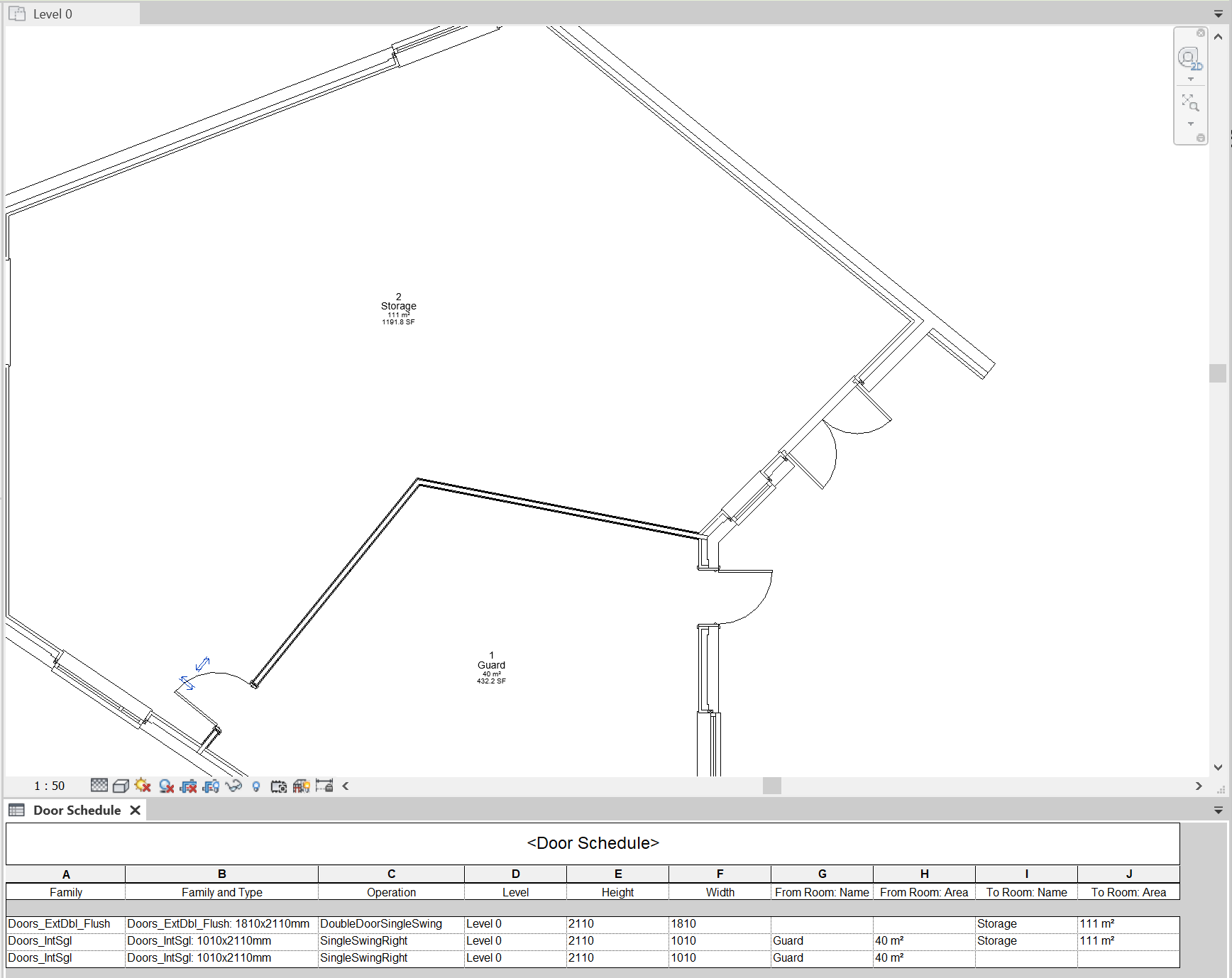
Many of the relations between symbols are present in BIM, even if they are not always obvious or directly accessible. Openings like doors and windows, for example, are hosted by a wall. They are normally entered in a model after the wall has been placed and in strict connection to it: moving a window out of the hosting wall is not allowed. Connected walls may also have a specific relation, e.g. co-termination: if one is moved, the others follow suit, staying connected in the same manner. Similarly, spaces know their bounding elements (which also precede them in the representation) and if any of these is modified, they automatically adapt themselves. Through such relations, many links between symbols are hidden in BIM. A door schedule, for example, (Figure 1) reveals that, in addition to its hosting wall, a door knows which two spaces it connects (or separates when closed).
Quite important is the explicit symbolic representation of both the ‘solids’ out of which a building is constructed (building elements like walls, floors, doors and windows) and the ‘voids’ of the building (the spaces bounded by the building elements). In analogue representations, the spaces are normally implicit, i.e. inferred by the reader. Having them explicit in BIM means that we can manipulate them directly and, quite significantly from the perspective of this book, attach to them information that cannot be linked to building elements. Similarly to specifying that a window is made of sustainable wood, one can specify that a space is intended for a particular use, e.g. “office” or for specific activities like “small group meeting” or “CEO’s meeting room”. Such characterizations relate to various requirements (usually found in the brief), such as floor area and performance specifications, e.g. acoustics or daylighting, which can also be attached to the space and used to guide and evaluate the design. Making spaces explicit in the representation therefore allows for full integration of building information in BIM and, through that, higher specificity and certainty. Spaces, after all, are the main reason and purpose of buildings, and most aspects are judged by how well spaces accommodate user activities.
BIM symbols and things
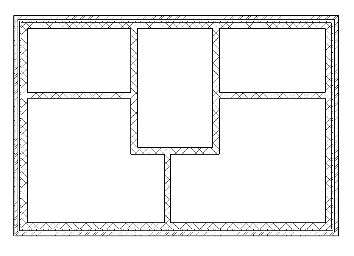
BIM has many advantages but, in common with other symbolic representations, also several ambiguities. One of the most important concerns the correspondence between symbols and real-world things. Building representations in BIM are truly symbolic, comprising discrete symbols. Unfortunately, the structure of building elements often introduces fuzziness in the definition of these symbols. In general, there are two categories of ‘solids’ in buildings. The first is building elements that are adequately represented by discrete symbols. Doors and windows, for example, are normally complete assemblies that are accommodated in a hole in a wall. Walls, on the other hand, are typical representatives of the second category: conceptual entities that are difficult to handle in three respects. Firstly, walls tend to consist of multiple layers of brickwork, insulation, plaster, paint and other materials. Some of these layers continue into other elements: the inner brick layer of an external wall may become the main layer of internal walls, forming a large, complex and continuous network that is locally incorporated in various walls (Figure 2).
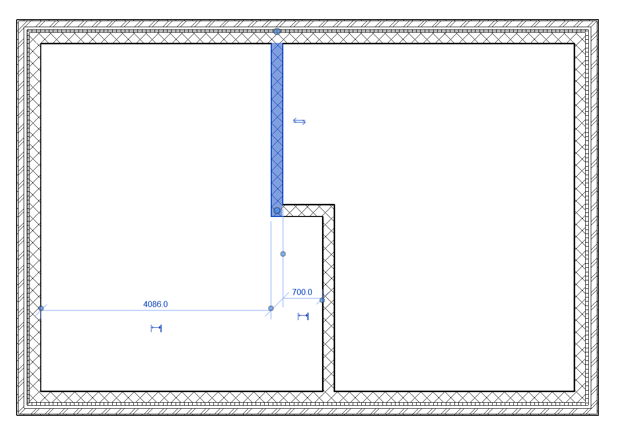
Secondly, BIM retains some of the geometric bias of earlier building representations, for example in the definition of elements like walls that have a fixed cross section but variable length or shape. When users have to enter the axis of a wall to describe this length or shape, they inevitably draw a geometric shape. BIM usually defines symbols on the basis of the most fundamental primitives in this shape. Even if one uses e.g. a rectangle to describe the axis, the result is four interconnected yet distinct walls, each corresponding to a side of the rectangle. Similarly, a wall with a complex shape but conceptually and practically unmistakably a single, continuous structure, may be analysed into several walls, each corresponding to a line segment of its axis (Figure 3).
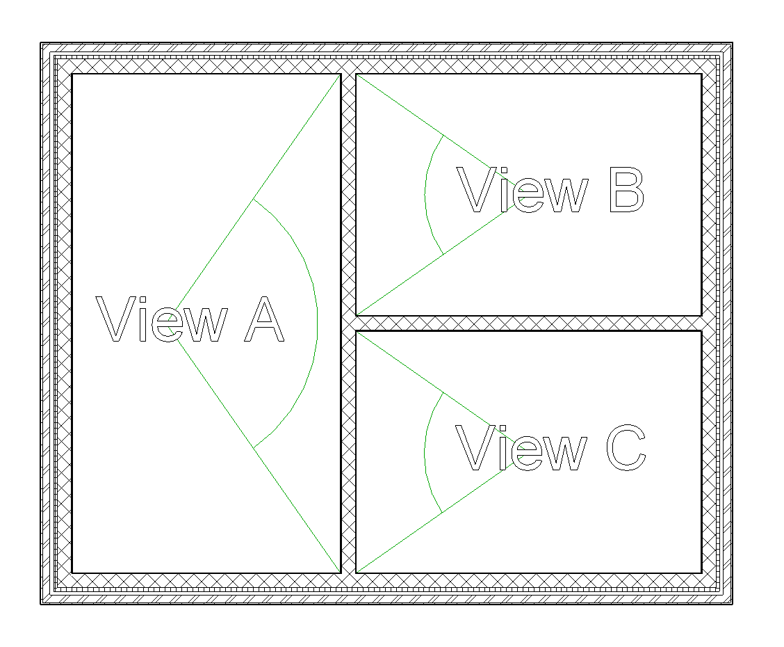
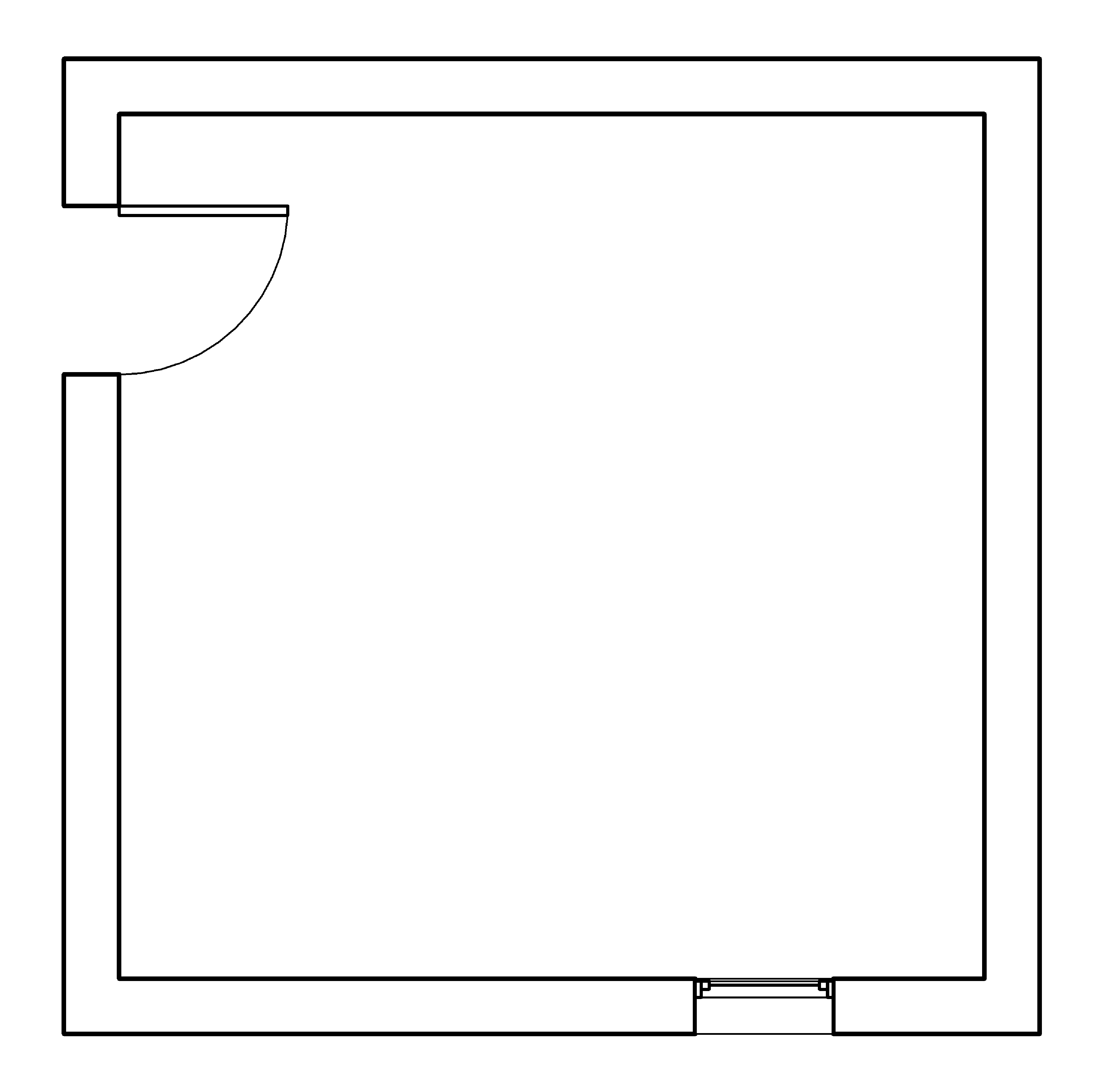
Thirdly, our own perception of elements like walls may get in the way. Standing on one side of a wall, we see only the portion of the wall that bounds the room we are in. Standing on the other side, we perceive not only a different face but possibly also a different part of the wall (Figure 4). As a result, when thinking from the perspective of either space, we refer to parts of the same entity as if they were different walls.
The inevitable conclusion is that some symbols in BIM may require further processing when considered with respect to particular goals. One may have to analyse a symbol into parts that are then combined with parts of other symbols, e.g. for scheduling the construction of the brick network in Figure 2. Other symbols must be grouped together by the user, for instance the internal wall in Figure 3. Such manipulations should not reduce the integrity of the symbols; it makes little sense to represent each layer of a wall separately. At the same time, one has to be both consistent and pragmatic in the geometric definition of building elements. In most cases, acceptance of the BIM preference for the simplest possible geometry is the least painful option: representing each of the two internal walls in Figure 4 as a single, separate entity is a compromise that accommodates all perspectives, including those indicated in the figure.
Abstraction and grouping in BIM
BIM symbols cover a wide range of abstraction levels, from generic symbols like “internal wall” without any further specifications to highly detailed symbols, e.g. of a very specific wall type, including precise descriptions of materials from particular manufacturers. A building representation in BIM often starts with abstract symbols, which become progressively more specific, in parallel with the design or construction process. It is also possible to backtrack to a higher abstraction level rather than sidestep to a different type on the same level, e.g. when some conflict resolution leads to a dead end and one needs to reconsider their options. This typologic abstraction is one of the strong points of BIM but also something one has to treat with care because a model may contain symbols at various abstraction levels. Managing the connections between them, e.g. deciding on the interfacing between a highly specific window and an abstract wall, requires attention to detail. On the positive side, one can use such connections to guide decision making, e.g. restrict the choice of wall type to those that match the expectations from the window.
Symbolic representations have considerable capacities for bottom-up grouping on the basis of explicit relations between symbols, ranging from similarity (e.g. all vowels in a text) to proximity (all letters in a word). As is typical of digital symbolic representations, BIM allows for various groupings of symbols, e.g. the set of all instances of the same door type in a design, all spaces with a particular use on the second floor or the parts of a design that belong to the north wing. For the latter, some additional user input may be required, such as a shape that represents the outline of the north wing or the labelling of every symbol with an additional wing property. No user input is required for relations built into the behavioural constraints of a symbol, e.g. the hosting of openings in walls.
Through the combination of standard symbol features (like their properties) and ad hoc, user-defined criteria (like the outline of a wing), one can process the representation at any relevant abstraction level and from multiple perspectives, always in direct reference to specific symbols. For example, it is possible to consider a specific beam in the context of its local function and connections to other elements but simultaneously with respect to the whole load-bearing structure in a single floor or the whole building. Any decision taken locally, specifically for this beam, relates transparently to either the instance or the type and may therefore lead not only to changes in the particular beam but also reconsideration of the beam types comprising the structure, e.g. a change of type for all similar beams. Reversely, any decision concerning the general type of the structure can be directly and automatically propagated to all of its members and their arrangement.
The automatic propagation of decisions relates to parametric modelling: the interconnection of symbol properties so that any modification to one symbol causes others to adapt accordingly (see Appendix II). In addition to what is built into the relations between types and instances or in behaviours like hosting, one can explicitly link instance properties, e.g. make several walls remain parallel to each other or vertical to another wall. One can also specify that the length of several walls is the same or a multiple of an explicitly defined parameter. Changing the value of the parameter leads to automatic modification of the length of all related walls. Parametric design holds significant promise. People have envisaged building representations in which it suffices to change a few values to produce a completely new design. However, establishing and maintaining the constraint propagation networks necessary for doing so in a reliable manner remains a major challenge. For the moment, parametric modelling is a clever way of grouping symbols with explicit reference to a relation underlying the grouping, e.g. parallelism of walls. Still, even in such simple cases, the effects of parametric relations in combination with built-in behaviours can lead to unpredictable or undesirable results.
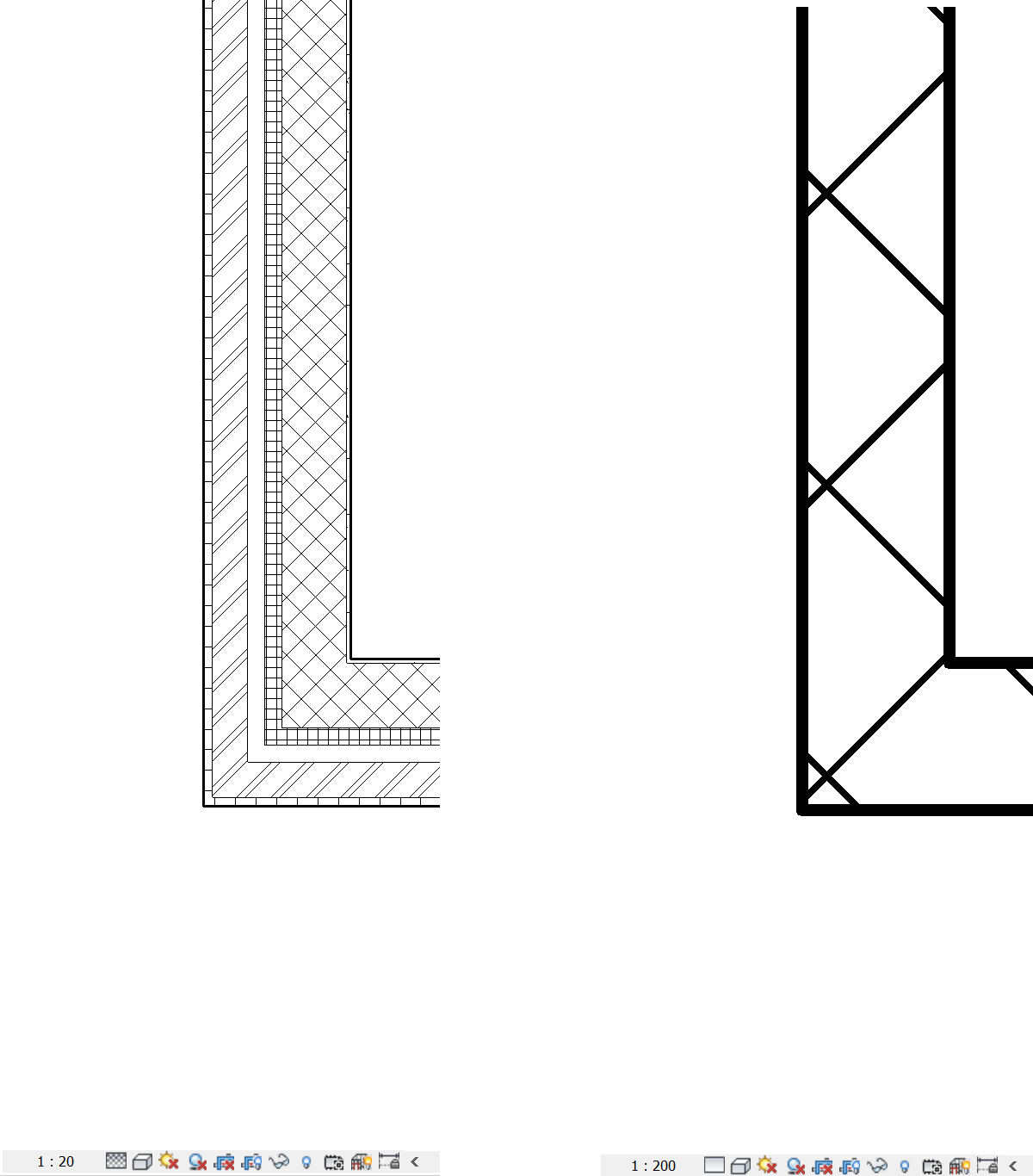
In views that replicate conventional drawings, BIM software often also incorporates visual abstraction that mimics that of scales in analogue representations. By selecting e.g. “1:20” and “fine” one can make the visual display of a floor plan more detailed than with “1:200” and “coarse” (Figure 5). Such settings are useful only for visual inspection; they alter only the appearance of symbols, not their type or structure.
The LoD (standard on the specificity of information in a model) is also related to abstraction. Adherence to LoD standards in a representation is a throwback to analogue standards regarding drawing scale and stage, which runs contrary to the integration and compression of stages advocated by BIM theory. LoD standardization often fails to appreciate that information in a model has a reason and a purpose: some people have taken decisions concerning some part or aspect of a design. The specificity of these decisions and of the resulting representations is not accidental or conventional. Rather, it reflects what is needed for that part or aspect at the particular stage of a project. The LoD of the model that accommodates this information can only be variable, as not all parts or aspects receive the same attention at any stage.
Specificity should therefore be driven by the need for information rather than by convention. If information in a representation is at a higher specificity level, one should not discard it but simply abstract in a meaningful way by focusing on relevant properties, relations or symbols. A useful analogy is with how human vision works: in your peripheral vision, you perceive vague forms and movement, e.g. something approaching you rapidly. If you turn your eyes and pay attention to these forms, you can see their details and recognize e.g. a friend rushing to meet you. As soon as you focus on these forms, other parts of what you perceive become vague and schematic. In other words, the world is as detailed as it is; your visual system is what makes some of its parts more abstract or specific, depending on your needs. By the same token, the specificity of a building representation should be as high as the available information allows. Our need for information determines the abstraction level at which we consider the representation, as well as actions by which we can increase the specificity of some of its parts.
Implementation mechanisms in BIM
Despite its symbolic structure, BIM appears to use the same implementation mechanisms as CAD: the same geometric primitives that reproduce the graphic, isomorphic appearance of analogue representations. The key difference is that these primitives are just part of pictorial views, in which they express certain symbol properties. The type of a door, for example, is explicitly named, so that we do not have to infer its swing from the arc used to represent it in a floor plan; the width of a wall is a numerical property of its symbol, so that we do not have to measure the distance between the two lines indicating the outer faces of the wall. On the contrary, this distance is determined by the width property of the symbol. These and other properties are explicit in the model database, making the Unicode symbols in it and their bits and bytes the true implementation mechanisms of BIM. Unfortunately, as this database remains largely hidden from view, users may fail to appreciate its significance.
The above covers the paradigmatic dimension, allowing us to consider any graphic primitive in a drawing view a mere product of real symbols. As we have seen, however, implementation mechanisms used in the syntagmatic dimension still influence the structure of a building representation in other respects: a wall is still partly determined by drawing its axis and so by the geometric shape one draws, as well as by dependencies between this shape to others in the model or view. On the whole, therefore, one should consider BIM largely immune to undue influences from graphic implementation mechanisms but at the same time remain aware of persistent geometric biases both in how BIM treats building representations and in the mindset of BIM users.
Models as graphs
Being symbolic representations, models in BIM can be described by graphs that express their structure in terms of symbols and their relations. These graphs are similar but not the same as the building, adjacency or access graphs discussed in a previous chapter: those are graphs that describe the design rather than the representation. In the graphs that describe a BIM model, symbols are usually represented by vertices and relations between symbols by edges (Figure 6 & 7). The edges often make explicit what is implicit in the model, for example, that each window or door is hosted by a particular wall and that walls connect to each other in a specific manner, e.g. co-terminate at the ends.
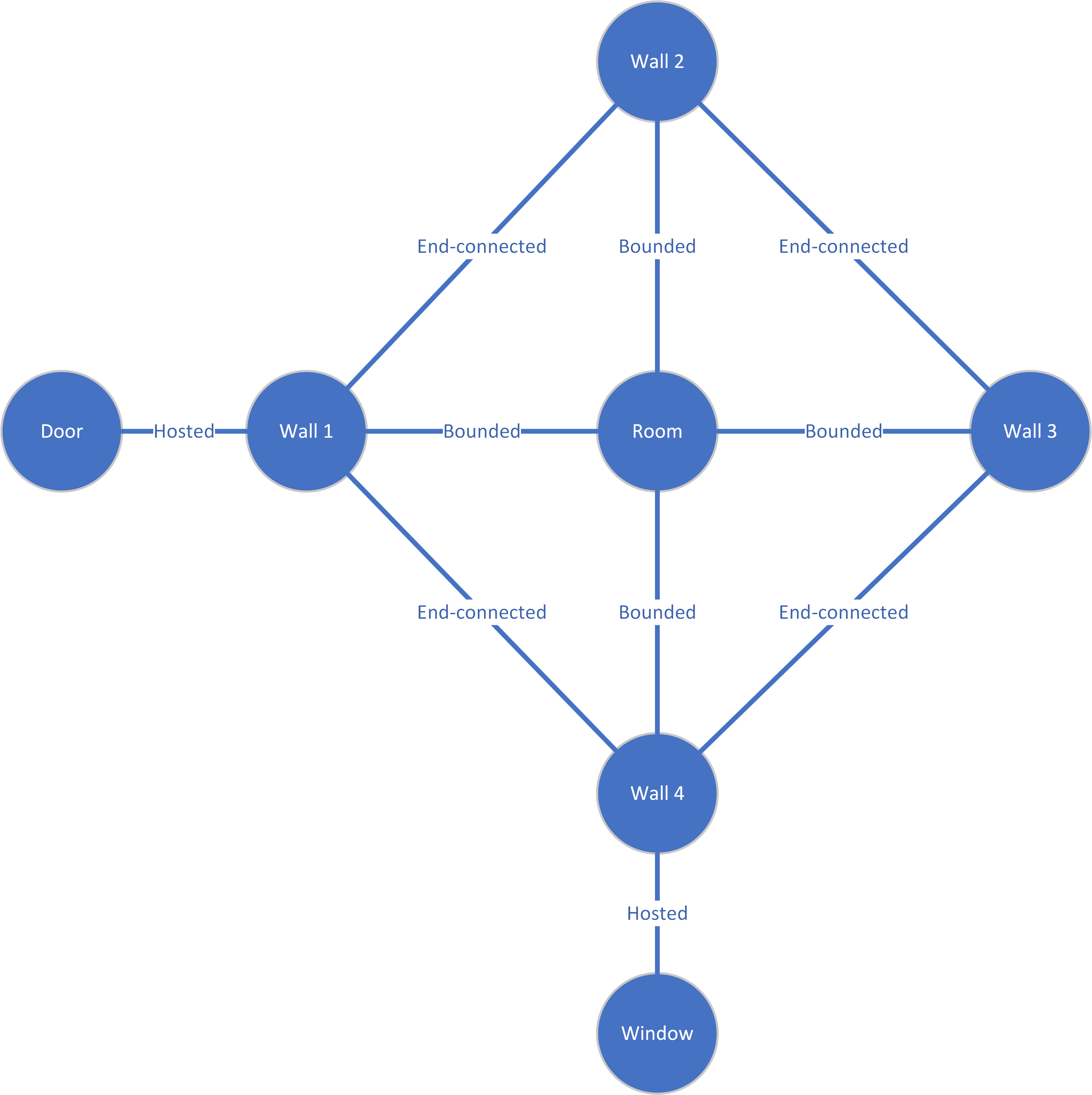
The graph summarizes the basic structure of the model: the entities it comprises and their basic relations, including dependencies, e.g. between the shape and size of the room and the configuration of walls that bound it. These relations and their constraints underlie many behaviours in BIM, for example, that doors and windows tend to stick to the hosting walls and that walls try to retain their end-connections.
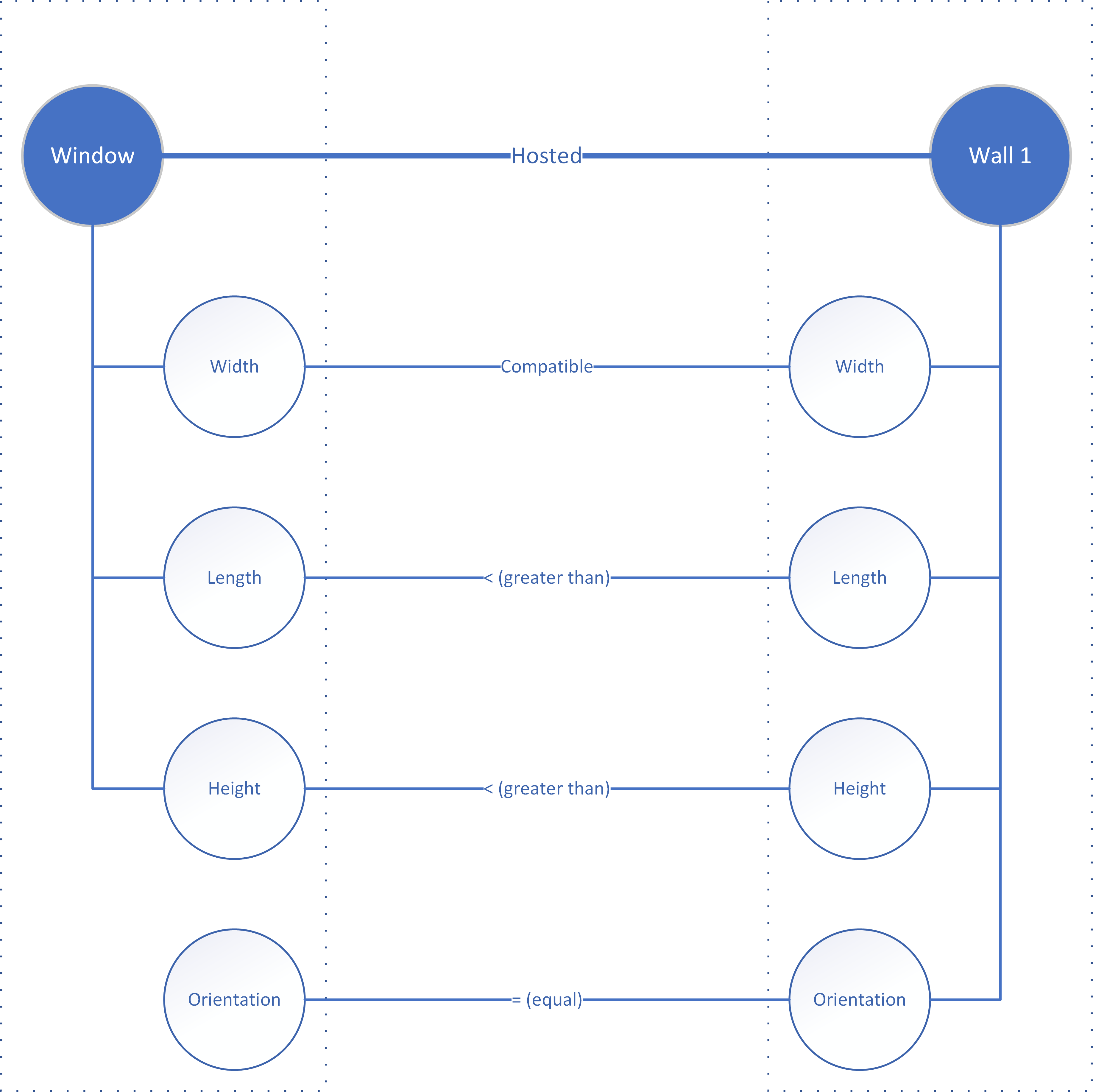
From an information perspective, this becomes even more interesting if we zoom in on the properties of the symbols and see how they are affected by relations and constraints, as in the case of a window and the wall that hosts it (Figure 8). Both elements are represented by discrete symbols, each with its own set of properties. The hosting relation means that some of the properties of the wall are inherited by the window. For example, the orientation of the window is by definition the same as the orientation of the wall. This constrains the behaviour of the window symbol when the user positions it in the model or modifies either the window or the wall.
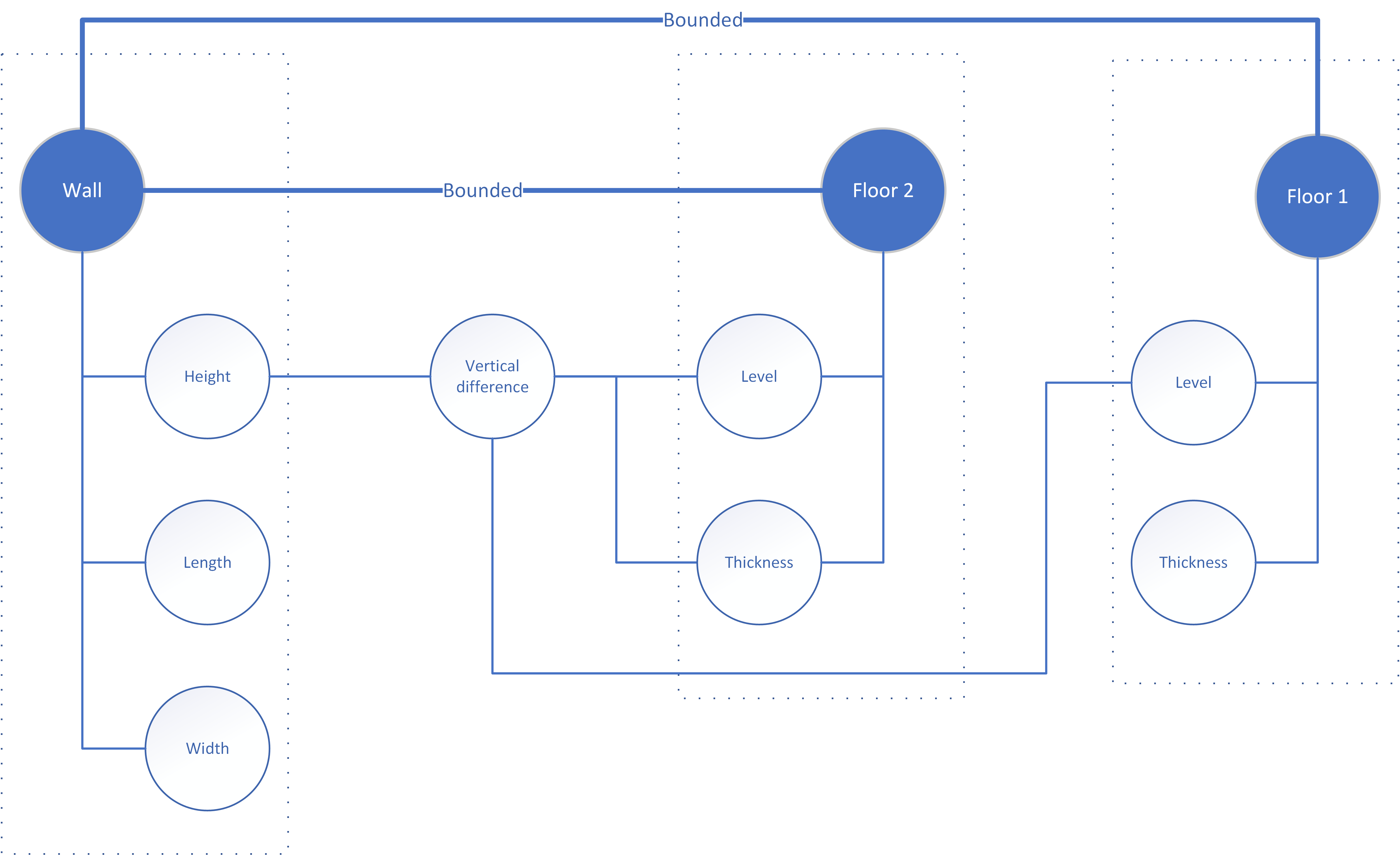
Describing such dependencies is especially important for relations that may be missing from the orthographic views and modelling workflows of BIM software, for example between walls and floors (Figure 9). The vertical dimensions of walls are usually determined by a combination of wall symbol properties and constraints, model setup (levels) and the presence of symbols like floors to which the top or base of a wall can attach. Users have to manipulate the wall and floor dimensions and relations in multiple views, which can be summarized in this rather simple graph that affords the overview necessary for IM.
Such graphs also reveal other relations that determine the compatibility of symbols in a relation (a type of parameterization that remains neglected). Wall and window width, for example, must be such that there is a technical solution for inserting the wall in the window: the width of a wall constraints the acceptability of window types. The same applies to length and height: assuming that the window comes in a standard size, the wall should be longer and higher (or at least equal) in order to accommodate it. The example seems trivial but dimensional incompatibilities of this kind are common in walls that combine multiple openings and different components.
Understanding the building representation in terms of symbols, relations and constraints is key to both parameterization and decision making. Therefore, it becomes a main task for IM. In addition to using graphs to describe the structure of a model, the model should be set up in a way that transparently expresses all dependencies and safeguards them effectively and consistently in all workflows. This concerns relations between symbols in the representation, as well as with external constraints, such as planning regulations, building codes and briefs. For example, modellers should make explicit the maximum height allowed by the planning regulations for a particular design and connect it to the relevant symbols and properties, e.g. the position of the roof. By doing this at the onset of a design project, they ensure that designers are aware of the constraints within which they work, e.g. that they are not allowed to place roofs or other elements higher than permitted. As will be discussed in following chapters, such feedforward that guides design is preferable to feedback, i.e. allowing designers to generate solutions that are then tested according to regulations they may have not taken into account.
Key Takeaways
- BIM is a truly symbolic building representation that employs discrete symbols to describe building elements and spaces
- Symbols in BIM integrate all properties of the symbolized entities, which determine their pictorial appearance
- BIM symbols are largely independent of graphic implementation mechanisms and immune to most geometric biases
- The correspondence between BIM symbols and some building elements is problematic in certain respects due to the structure of these elements, persisting geometric biases and human perception
- Abstraction in BIM is both typological (as symbols are at various abstraction levels) and mnemonic (based on similarity of properties and relations like proximity and hosting between symbols)
- Models in BIM can be described by graphs of symbols and relations; these graphs afford the overview and transparency missing from BIM software interfaces
Exercises
- In a BIM editor of your choice (e.g. Revit), make an inventory of all wall types (Families in Revit) in the supplied library. Classify these types in terms of abstraction, clearly specifying your criteria.
- In a BIM editor of your choice, make a simple design of a space with four walls and two floors around it. Identify properties of the building elements and space symbols that connect them (e.g. dimensions) and overlapping properties (e.g. space properties that refer to finishings of the building elements).
- Make schedules and graphs that illustrate your findings.
- Compare the schedules and graphs.
- Expand your design with another space and a door that connects them. Make a schedule and a graph that illustrate the key relations between the spaces.
- In the expanded design, describe step by step how a change in the size of one room is propagated to other symbols in the model.
- A comprehensive general introduction to BIM is: Eastman, C., Teicholz, P.M., Sacks, R., & Lee, G., 2018. BIM handbook (3rd ed.). Hoboken NJ: Wiley. ↵