5.4: Conduit, Boxes, and Wiring
- Page ID
- 2328
\( \newcommand{\vecs}[1]{\overset { \scriptstyle \rightharpoonup} {\mathbf{#1}} } \)
\( \newcommand{\vecd}[1]{\overset{-\!-\!\rightharpoonup}{\vphantom{a}\smash {#1}}} \)
\( \newcommand{\id}{\mathrm{id}}\) \( \newcommand{\Span}{\mathrm{span}}\)
( \newcommand{\kernel}{\mathrm{null}\,}\) \( \newcommand{\range}{\mathrm{range}\,}\)
\( \newcommand{\RealPart}{\mathrm{Re}}\) \( \newcommand{\ImaginaryPart}{\mathrm{Im}}\)
\( \newcommand{\Argument}{\mathrm{Arg}}\) \( \newcommand{\norm}[1]{\| #1 \|}\)
\( \newcommand{\inner}[2]{\langle #1, #2 \rangle}\)
\( \newcommand{\Span}{\mathrm{span}}\)
\( \newcommand{\id}{\mathrm{id}}\)
\( \newcommand{\Span}{\mathrm{span}}\)
\( \newcommand{\kernel}{\mathrm{null}\,}\)
\( \newcommand{\range}{\mathrm{range}\,}\)
\( \newcommand{\RealPart}{\mathrm{Re}}\)
\( \newcommand{\ImaginaryPart}{\mathrm{Im}}\)
\( \newcommand{\Argument}{\mathrm{Arg}}\)
\( \newcommand{\norm}[1]{\| #1 \|}\)
\( \newcommand{\inner}[2]{\langle #1, #2 \rangle}\)
\( \newcommand{\Span}{\mathrm{span}}\) \( \newcommand{\AA}{\unicode[.8,0]{x212B}}\)
\( \newcommand{\vectorA}[1]{\vec{#1}} % arrow\)
\( \newcommand{\vectorAt}[1]{\vec{\text{#1}}} % arrow\)
\( \newcommand{\vectorB}[1]{\overset { \scriptstyle \rightharpoonup} {\mathbf{#1}} } \)
\( \newcommand{\vectorC}[1]{\textbf{#1}} \)
\( \newcommand{\vectorD}[1]{\overrightarrow{#1}} \)
\( \newcommand{\vectorDt}[1]{\overrightarrow{\text{#1}}} \)
\( \newcommand{\vectE}[1]{\overset{-\!-\!\rightharpoonup}{\vphantom{a}\smash{\mathbf {#1}}}} \)
\( \newcommand{\vecs}[1]{\overset { \scriptstyle \rightharpoonup} {\mathbf{#1}} } \)
\( \newcommand{\vecd}[1]{\overset{-\!-\!\rightharpoonup}{\vphantom{a}\smash {#1}}} \)
\(\newcommand{\avec}{\mathbf a}\) \(\newcommand{\bvec}{\mathbf b}\) \(\newcommand{\cvec}{\mathbf c}\) \(\newcommand{\dvec}{\mathbf d}\) \(\newcommand{\dtil}{\widetilde{\mathbf d}}\) \(\newcommand{\evec}{\mathbf e}\) \(\newcommand{\fvec}{\mathbf f}\) \(\newcommand{\nvec}{\mathbf n}\) \(\newcommand{\pvec}{\mathbf p}\) \(\newcommand{\qvec}{\mathbf q}\) \(\newcommand{\svec}{\mathbf s}\) \(\newcommand{\tvec}{\mathbf t}\) \(\newcommand{\uvec}{\mathbf u}\) \(\newcommand{\vvec}{\mathbf v}\) \(\newcommand{\wvec}{\mathbf w}\) \(\newcommand{\xvec}{\mathbf x}\) \(\newcommand{\yvec}{\mathbf y}\) \(\newcommand{\zvec}{\mathbf z}\) \(\newcommand{\rvec}{\mathbf r}\) \(\newcommand{\mvec}{\mathbf m}\) \(\newcommand{\zerovec}{\mathbf 0}\) \(\newcommand{\onevec}{\mathbf 1}\) \(\newcommand{\real}{\mathbb R}\) \(\newcommand{\twovec}[2]{\left[\begin{array}{r}#1 \\ #2 \end{array}\right]}\) \(\newcommand{\ctwovec}[2]{\left[\begin{array}{c}#1 \\ #2 \end{array}\right]}\) \(\newcommand{\threevec}[3]{\left[\begin{array}{r}#1 \\ #2 \\ #3 \end{array}\right]}\) \(\newcommand{\cthreevec}[3]{\left[\begin{array}{c}#1 \\ #2 \\ #3 \end{array}\right]}\) \(\newcommand{\fourvec}[4]{\left[\begin{array}{r}#1 \\ #2 \\ #3 \\ #4 \end{array}\right]}\) \(\newcommand{\cfourvec}[4]{\left[\begin{array}{c}#1 \\ #2 \\ #3 \\ #4 \end{array}\right]}\) \(\newcommand{\fivevec}[5]{\left[\begin{array}{r}#1 \\ #2 \\ #3 \\ #4 \\ #5 \\ \end{array}\right]}\) \(\newcommand{\cfivevec}[5]{\left[\begin{array}{c}#1 \\ #2 \\ #3 \\ #4 \\ #5 \\ \end{array}\right]}\) \(\newcommand{\mattwo}[4]{\left[\begin{array}{rr}#1 \amp #2 \\ #3 \amp #4 \\ \end{array}\right]}\) \(\newcommand{\laspan}[1]{\text{Span}\{#1\}}\) \(\newcommand{\bcal}{\cal B}\) \(\newcommand{\ccal}{\cal C}\) \(\newcommand{\scal}{\cal S}\) \(\newcommand{\wcal}{\cal W}\) \(\newcommand{\ecal}{\cal E}\) \(\newcommand{\coords}[2]{\left\{#1\right\}_{#2}}\) \(\newcommand{\gray}[1]{\color{gray}{#1}}\) \(\newcommand{\lgray}[1]{\color{lightgray}{#1}}\) \(\newcommand{\rank}{\operatorname{rank}}\) \(\newcommand{\row}{\text{Row}}\) \(\newcommand{\col}{\text{Col}}\) \(\renewcommand{\row}{\text{Row}}\) \(\newcommand{\nul}{\text{Nul}}\) \(\newcommand{\var}{\text{Var}}\) \(\newcommand{\corr}{\text{corr}}\) \(\newcommand{\len}[1]{\left|#1\right|}\) \(\newcommand{\bbar}{\overline{\bvec}}\) \(\newcommand{\bhat}{\widehat{\bvec}}\) \(\newcommand{\bperp}{\bvec^\perp}\) \(\newcommand{\xhat}{\widehat{\xvec}}\) \(\newcommand{\vhat}{\widehat{\vvec}}\) \(\newcommand{\uhat}{\widehat{\uvec}}\) \(\newcommand{\what}{\widehat{\wvec}}\) \(\newcommand{\Sighat}{\widehat{\Sigma}}\) \(\newcommand{\lt}{<}\) \(\newcommand{\gt}{>}\) \(\newcommand{\amp}{&}\) \(\definecolor{fillinmathshade}{gray}{0.9}\)Conduit
Raceways are defined as enclosed channels of metal or nonmetallic material designed expressly for holding wires or cables. Branch-circuit installation using a raceway (conduit) wiring method is seldom used in residential wiring. However, some areas of the country require that all wiring in a house be installed in a raceway wiring method. Raceways should be installed as a complete system and be securely fastened in place and supported by an approved retainer.
Use individual conductors when installing a circuit in a raceway wiring method. It is common wiring practice to install a green insulated equipment grounding conductor in every raceway. Electric codes have specific requirements for wiring in different types of conduit that include allowable fill rates that vary depending upon wire size and insulation type.
The following conduits are used primarily in light to heavy commercial application and are listed here for your reference:
Rigid metal conduit (RMC)– RMC is generally made of steel with a protective galvanized coating. It is a threadable raceway designed for the physical protection and routing of conductors and cables and for use as an equipment grounding conductor when installed with appropriate fittings. It can be used in all atmospheric conditions and forms of occupancy. Requires pipe and thread cutting specialty tools.
Intermediate metal conduit (IMC)– IMC is a thinner-walled version of rigid metal conduit and can be used in all locations in a house where rigid metal conduit is permitted to be used. It can be used as an equipment grounding conductor when installed with associated couplings and appropriate fittings. Requires pipe and thread cutting specialty tools.
Raceways used in residential wiring include:
Query \(\PageIndex{1}\)
EMT Conduit Bending
Bending conduit is a skill that improves with practice. The most common electrical conduit installed in houses is EMT and, for this reason, the discussion that follows on conduit bending will focus on EMT. The bending techniques described may also apply to the other types of circular metal raceways.
EMT is bent in the field using either a hand bender, a hydraulic bender, or an electric bender. Bend sizes 1/2″ through 1-1/4″ are usually formed with a hand bender. A hydraulic or electric power bender is generally used for larger sizes. Since most EMT installed in houses will be 1/2″, 3/4″, or 1″ trade sizes, we will focus on bending with a hand bender.
When making a bend using a hand bender:
- Wear safety glasses and observe all applicable safety rules.
- Bend on a flat surface that is not slippery.
- Mark the locations on the conduit where you wish to make the bends clearly and accurately.
- Apply heavy foot pressure on the foot pedal to keep the conduit tightly in the bender.
- When making multiple bends on the same pipe length, keep all bends in the same plane.
IDEAL Hand Conduit Benders
Query \(\PageIndex{2}\)
IDEAL Benders How To Bend a Stub
Query \(\PageIndex{3}\)
IDEAL Hand Conduit Bender How to Make a Back to Back Bend
Query \(\PageIndex{4}\)
Conduit Bending Basics 3 Bend Saddle
Query \(\PageIndex{5}\)
Boxes
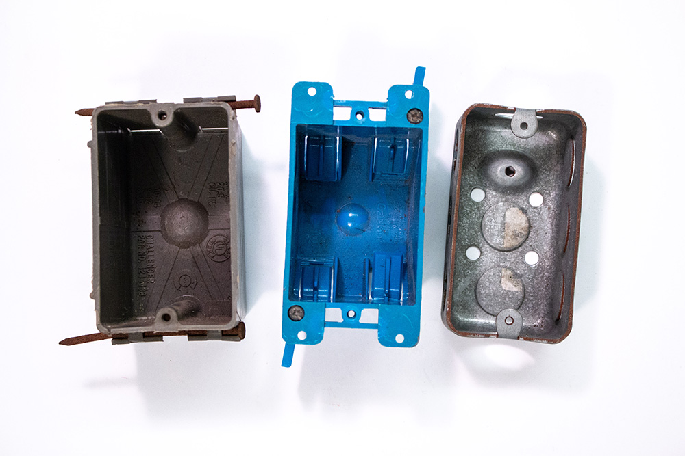
Electrical Boxes by Gwen Arkin is licensed under CC BY 4.0
Electrical boxes have many mounting options that range from configurations designed to be nailed or screwed to framing members or blocking, to models for remodeling (called an “old work” box) that attach to the sheetrock that encloses a wall pocket.
Device Boxes- are used to install receptacles or switches at specific locations on an electrical circuit. Standard box openings are approximately 3″ x 2″ with a depth that ranges from 1-1/2″ to 3-1/2″.
Outlet Boxes- are used when installing lighting fixtures in a ceiling or on a wall and when connecting small or large appliances. They are larger than a device box and provide more room for different wiring situations. Outlet boxes are offered in round, octagon, or square shapes.
Junction Boxes (J-Box)- These are used when several conductors are spliced together at a point on the wiring system. The NEC® requires junction boxes to be accessible after installation without the finish of a building having to be altered. Junction boxes must always be covered.
Heavy Load Boxes- Specifically designed and tested to support heavier loads. Used for heavier loads such as ceiling suspended paddle fans. Heavy load boxes can be manufactured with metal or nonmetal material.
Metal Boxes
A metal device box often includes the capability of having the sides of the box removed and the boxes ganged together to make a box that can accommodate multiple devices. The most common metal device box size 3″ x 2″ x 3-1/2″. Another type of metallic device box recognized by the NEC® is the “handy” or “utility” box. This type of box is primarily used for surface mounting and can accommodate one device such as a receptacle or switch.
Nonmetallic Device Boxes
Nonmetallic boxes are usually made of PVC, phenolic, or polycarbonate. The specific advantages of using these boxes include that they are lightweight, strong, very easy to install, and inexpensive. Most all nonmetallic boxes are wired using a nonmetallicsheathed cable wiring method. Nonmetallic boxes are offered in single-gang, two-gang, three-gang device box, and fixture mounting styles.
PVC Conduit Boxes
Although PVC boxes are designed and used for glue-up assembly, some models have female threaded fittings to accommodate a variety of threaded connectors.
Wires (Conductors)
Conductors in residential wiring are usually installed in a cable assembly. They are made of copper, aluminum, and copper-clad aluminum. Copper is preferred because of its great ability to conduct electricity, its strength, and its low instance of problems over the long term.
Conductors are sized according to the American Wire Gauge (AWG). Conductors used in residential wiring typically range in size from 14 AWG to 2/0 copper. The larger the number, the smaller the conductor. The smaller the number, the larger the conductor. Conductor sizes larger than 4/0 are listed in kcmil (1000 circular mils).
Ampacity is the current in amperes that a conductor can carry continuously under the conditions of use without exceeding its temperature rating. A residential electrician or maintenance technician must be able to choose the correct conductor size based on the ampacity needed for each circuit they are working with. The ampacity of a conductor depends not only on the diameter size of the conductor, but also on the length of the conductor, and what insulation type the conductor has.
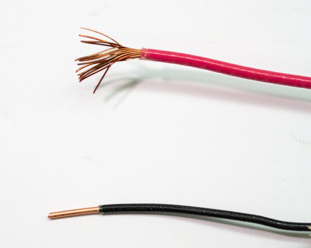
Stranded Wire vs Solid Wire by Gwen Arkin is licensed under CC BY 4.0
THHN and THWN are codes for the two most common types of insulated wire used inside conduit. These types of conductors are often used in conjunction with flexible conduit in unfinished areas, such as basements and garages, and for short exposed runs inside the home, such as wiring connections for garbage disposers and hot water heaters. They are also used in solid material conduit branch circuits. The letters indicate specific properties of the wire insulation:
T: thermoplastic
H: heat-resistant; HH means highly heat-resistant
W: rated for wet locations
N: nylon-coated, for added protection
Solid Core VS. Stranded Wire- While solid wire consists of a single metal core, while a stranded wire is composed of numerous thinner wires twisted together into a cohesive bunch. Both types of wire are appropriate for commercial and residential installation, however each has particular advantages and disadvantages that lead to the choice of one over another for each particular application.
| USE | SOLID WIRE | STRANDED WIRE |
|---|---|---|
| Protection against corrosion | YES | NO |
| Outdoor use | YES | NO |
| Price advantage | YES | NO |
| Where flexibility is important | NO | YES |
| Repetitive motion | NO | YES |
Wire Color and Use
Color choice for the insulation of the conductors installed in a raceway depends on the type of circuit it serves.
• For a 120-volt branch circuit, use a white insulated wire and a black insulated wire.
• For a straight 240-volt circuit (like an electric water heater), use two black conductors or a black and a red conductor.
• If the circuit is a 120/240-volt circuit (like an electric clothes dryer), run a white insulated wire, a black insulated wire, and a red insulated wire.
The NEC® requires that each conductor be color coded to indicate the function that it performs in a circuit.
Black– Used as an ungrounded or “hot” conductor and carries the current to the load in 120-volt circuits.
Red– Also used as an ungrounded or “hot” conductor and carries current to the load in 120/240-volt circuits like an electric clothes dryer circuit.
White– Used as the grounded circuit conductor
– Returns current from the load back to the source
– Called “neutral” conductor, but only true “neutral” when used with black and red wire in multi-wire circuit
Bare– Used as equipment grounding conductor that bonds all non-current carrying metal parts of a circuit together; never carries current.
Green (can be green with yellow stripes)– Used as an insulated equipment grounding conductor; never carries current.
Conductor Installation
Conductors are usually pulled into the conduit, but in shorter runs between electrical boxes conductors they may be pushed through the raceway. Conductors are taken off spools in a way that results in the conductors coming off the spools easily and not becoming tangled with each other. One of the easiest ways to do this is to use a wire cart that allows several spools of wire to be put on at one time.
If the length of conduit between boxes is fairly long, use a fish tape. If the conduit already contains wires, be sure the circuits that supply them are de-energized. Pull the fish tape out of its reel. Insert it into a raceway and push it through until it comes out at a box location. The fish tape will have a hook on the end of it. Attach the conductors to the fish tape end. While one person pulls the conductors slowly off the spools, another person will pull the fish tape with the attached conductors back through the raceway.
Klein Tools Laser-etched Fiberglass Fish Tapes
Query \(\PageIndex{6}\)
If the length of a conduit run is longer than the length of your longest fish tape, another technique can be used. One technique uses a vacuum/compression device to blow or suck a “mouse” with a string tied to it though the length of conduit. Once the mouse has been blown or sucked through the conduit, the attached string is removed from the mouse and tied to a stronger pulling rope, which is then pulled though the conduit. The pulling rope is then attached to the wires and they are pulled into the conduit.
Terminations
Query \(\PageIndex{7}\)
Cable Types
Cable wiring methods are easier to install than raceway wiring methods, and this is the main reason why most houses are wired using as little conduit as possible. Cable wire contains all of the conductors needed for the circuit in a single insulated unit.
When purchasing cable wiring system the cable is referred to by two numbers: the first number specifies the gauge; the second the number of current carrying conductors in the wire. Additionally, there’s usually another wire that is used for grounding (green or bare). “12-2” means 12 gauge, two insulated current carrying wires, and a bare ground. 12-2 wire usually has a black, white and bare ground wire. Black, red, and a ground with no white wire is used for 220V circuits without neutral. 12-3 wire usually has a black, red, white and bare ground wire and is used for 220V with neutral or in three-way switch applications as the traveler between the switches where an additional wire is required.
Nonmetallic-Sheathed Cable (Type NM)- Also known as “Romex”. Least expensive and most used residential wiring method to purchase and install.
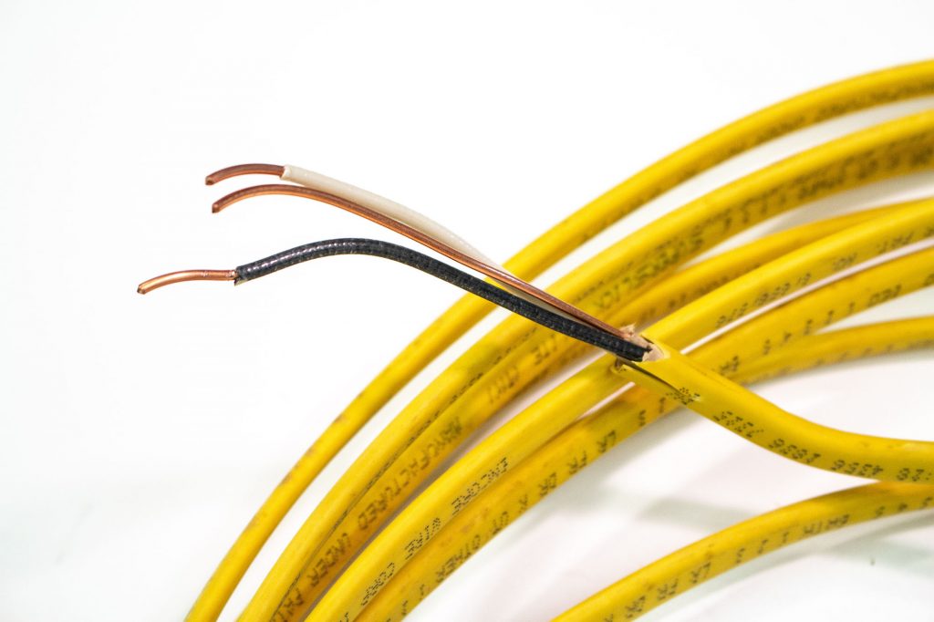
Romex® Cable by Gwen Arkin is licensed under CC BY 4.0
Types of Type NM cable:
- Type NM-B (white outer jacket)- Most common type; use in dry locations only. Has a flame-retardant, moisture-resistant, nonmetallic outer jacket.
- Type NMC-B (yellow outer jacket)- Not used often in residential work ; use in dry or damp locations. Has a flame retardant, fungus and corrosion resistant, nonmetallic outer jacket.
- Type NMS-B (orange outer jacket)- Used in new homes with home automation systems. Contains power conductors, telephone wires, coaxial cable for video, and other data conductors all in the same cable. Has moisture-resistant, flame-retardant, nonmetallic outer jacket.
Underground Feeder Cable (Type UF)- Used for underground installation of branch circuits and feeder circuits. Also used in interior installations, but must be installed following the installation requirements for Nonmetallic-Sheathed Cable.
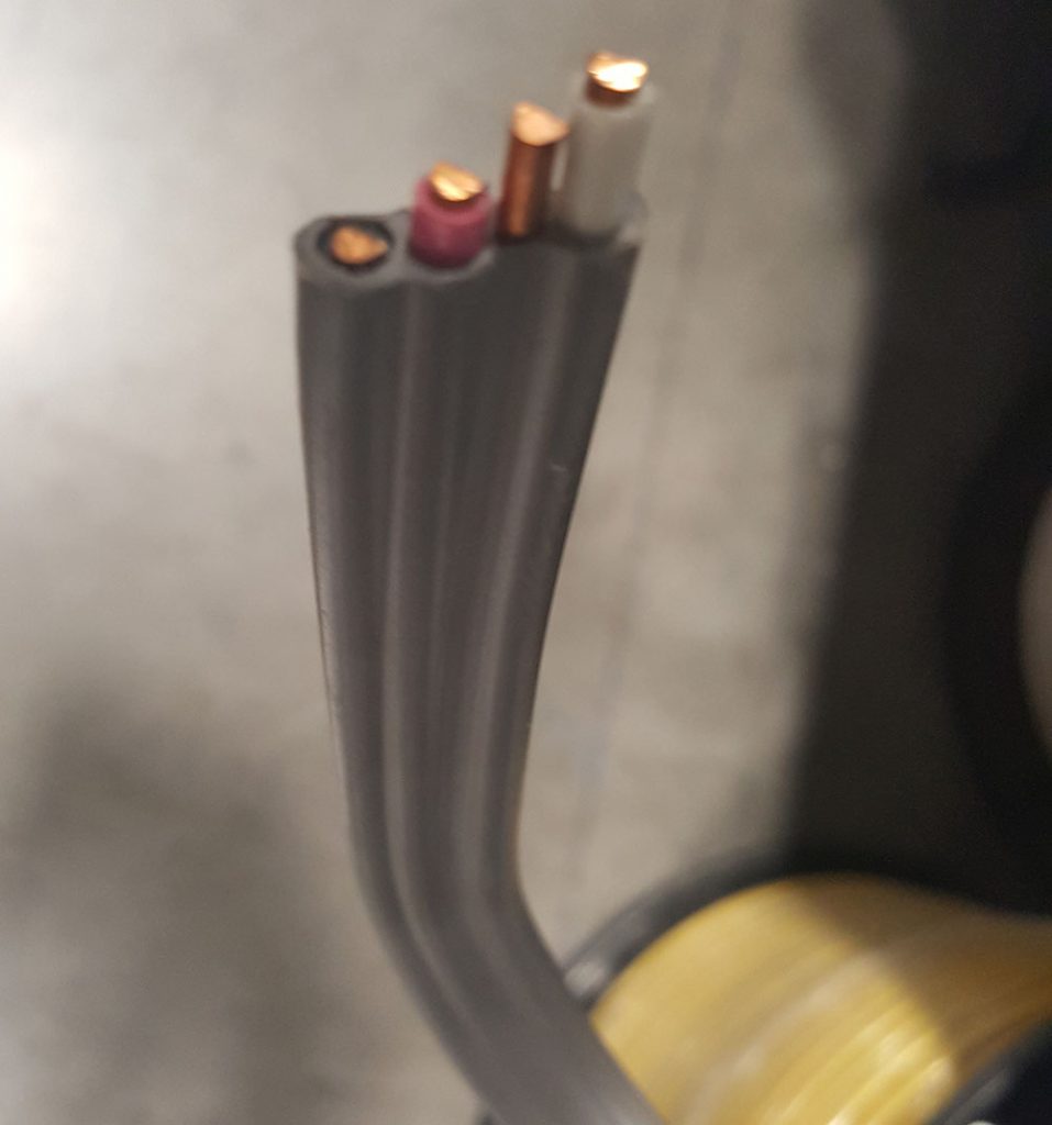
Underground Feeder Cable (Type UF) by Clifford Rutherford is licensed under CC BY 4.0
Armored-Clad (Type AC) and Metal-Clad (Type MC) Cable- Certain locations in the United States may not allow Nonmetallic Sheathed Cable in residential construction. Both have a metal outer sheathing and provide very high levels of physical protection for the conductors in the cable. Electricians sometimes find it hard to tell Type AC (also known as “BX” cable) and Type MC apart. Type AC cable has brown paper covering each conductor and Type MC cable has a clear plastic wrap around all of the conductors.
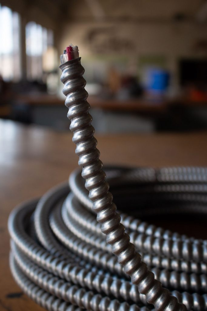
Metal-Clad (MC) Cable by Gwen Arkin is licensed under CC BY 4.0


