
5.6: Receptacle and Switch Wiring
- Page ID
- 2330

\( \newcommand{\vecs}[1]{\overset { \scriptstyle \rightharpoonup} {\mathbf{#1}} } \)
\( \newcommand{\vecd}[1]{\overset{-\!-\!\rightharpoonup}{\vphantom{a}\smash {#1}}} \)
\( \newcommand{\dsum}{\displaystyle\sum\limits} \)
\( \newcommand{\dint}{\displaystyle\int\limits} \)
\( \newcommand{\dlim}{\displaystyle\lim\limits} \)
\( \newcommand{\id}{\mathrm{id}}\) \( \newcommand{\Span}{\mathrm{span}}\)
( \newcommand{\kernel}{\mathrm{null}\,}\) \( \newcommand{\range}{\mathrm{range}\,}\)
\( \newcommand{\RealPart}{\mathrm{Re}}\) \( \newcommand{\ImaginaryPart}{\mathrm{Im}}\)
\( \newcommand{\Argument}{\mathrm{Arg}}\) \( \newcommand{\norm}[1]{\| #1 \|}\)
\( \newcommand{\inner}[2]{\langle #1, #2 \rangle}\)
\( \newcommand{\Span}{\mathrm{span}}\)
\( \newcommand{\id}{\mathrm{id}}\)
\( \newcommand{\Span}{\mathrm{span}}\)
\( \newcommand{\kernel}{\mathrm{null}\,}\)
\( \newcommand{\range}{\mathrm{range}\,}\)
\( \newcommand{\RealPart}{\mathrm{Re}}\)
\( \newcommand{\ImaginaryPart}{\mathrm{Im}}\)
\( \newcommand{\Argument}{\mathrm{Arg}}\)
\( \newcommand{\norm}[1]{\| #1 \|}\)
\( \newcommand{\inner}[2]{\langle #1, #2 \rangle}\)
\( \newcommand{\Span}{\mathrm{span}}\) \( \newcommand{\AA}{\unicode[.8,0]{x212B}}\)
\( \newcommand{\vectorA}[1]{\vec{#1}} % arrow\)
\( \newcommand{\vectorAt}[1]{\vec{\text{#1}}} % arrow\)
\( \newcommand{\vectorB}[1]{\overset { \scriptstyle \rightharpoonup} {\mathbf{#1}} } \)
\( \newcommand{\vectorC}[1]{\textbf{#1}} \)
\( \newcommand{\vectorD}[1]{\overrightarrow{#1}} \)
\( \newcommand{\vectorDt}[1]{\overrightarrow{\text{#1}}} \)
\( \newcommand{\vectE}[1]{\overset{-\!-\!\rightharpoonup}{\vphantom{a}\smash{\mathbf {#1}}}} \)
\( \newcommand{\vecs}[1]{\overset { \scriptstyle \rightharpoonup} {\mathbf{#1}} } \)
\(\newcommand{\longvect}{\overrightarrow}\)
\( \newcommand{\vecd}[1]{\overset{-\!-\!\rightharpoonup}{\vphantom{a}\smash {#1}}} \)
\(\newcommand{\avec}{\mathbf a}\) \(\newcommand{\bvec}{\mathbf b}\) \(\newcommand{\cvec}{\mathbf c}\) \(\newcommand{\dvec}{\mathbf d}\) \(\newcommand{\dtil}{\widetilde{\mathbf d}}\) \(\newcommand{\evec}{\mathbf e}\) \(\newcommand{\fvec}{\mathbf f}\) \(\newcommand{\nvec}{\mathbf n}\) \(\newcommand{\pvec}{\mathbf p}\) \(\newcommand{\qvec}{\mathbf q}\) \(\newcommand{\svec}{\mathbf s}\) \(\newcommand{\tvec}{\mathbf t}\) \(\newcommand{\uvec}{\mathbf u}\) \(\newcommand{\vvec}{\mathbf v}\) \(\newcommand{\wvec}{\mathbf w}\) \(\newcommand{\xvec}{\mathbf x}\) \(\newcommand{\yvec}{\mathbf y}\) \(\newcommand{\zvec}{\mathbf z}\) \(\newcommand{\rvec}{\mathbf r}\) \(\newcommand{\mvec}{\mathbf m}\) \(\newcommand{\zerovec}{\mathbf 0}\) \(\newcommand{\onevec}{\mathbf 1}\) \(\newcommand{\real}{\mathbb R}\) \(\newcommand{\twovec}[2]{\left[\begin{array}{r}#1 \\ #2 \end{array}\right]}\) \(\newcommand{\ctwovec}[2]{\left[\begin{array}{c}#1 \\ #2 \end{array}\right]}\) \(\newcommand{\threevec}[3]{\left[\begin{array}{r}#1 \\ #2 \\ #3 \end{array}\right]}\) \(\newcommand{\cthreevec}[3]{\left[\begin{array}{c}#1 \\ #2 \\ #3 \end{array}\right]}\) \(\newcommand{\fourvec}[4]{\left[\begin{array}{r}#1 \\ #2 \\ #3 \\ #4 \end{array}\right]}\) \(\newcommand{\cfourvec}[4]{\left[\begin{array}{c}#1 \\ #2 \\ #3 \\ #4 \end{array}\right]}\) \(\newcommand{\fivevec}[5]{\left[\begin{array}{r}#1 \\ #2 \\ #3 \\ #4 \\ #5 \\ \end{array}\right]}\) \(\newcommand{\cfivevec}[5]{\left[\begin{array}{c}#1 \\ #2 \\ #3 \\ #4 \\ #5 \\ \end{array}\right]}\) \(\newcommand{\mattwo}[4]{\left[\begin{array}{rr}#1 \amp #2 \\ #3 \amp #4 \\ \end{array}\right]}\) \(\newcommand{\laspan}[1]{\text{Span}\{#1\}}\) \(\newcommand{\bcal}{\cal B}\) \(\newcommand{\ccal}{\cal C}\) \(\newcommand{\scal}{\cal S}\) \(\newcommand{\wcal}{\cal W}\) \(\newcommand{\ecal}{\cal E}\) \(\newcommand{\coords}[2]{\left\{#1\right\}_{#2}}\) \(\newcommand{\gray}[1]{\color{gray}{#1}}\) \(\newcommand{\lgray}[1]{\color{lightgray}{#1}}\) \(\newcommand{\rank}{\operatorname{rank}}\) \(\newcommand{\row}{\text{Row}}\) \(\newcommand{\col}{\text{Col}}\) \(\renewcommand{\row}{\text{Row}}\) \(\newcommand{\nul}{\text{Nul}}\) \(\newcommand{\var}{\text{Var}}\) \(\newcommand{\corr}{\text{corr}}\) \(\newcommand{\len}[1]{\left|#1\right|}\) \(\newcommand{\bbar}{\overline{\bvec}}\) \(\newcommand{\bhat}{\widehat{\bvec}}\) \(\newcommand{\bperp}{\bvec^\perp}\) \(\newcommand{\xhat}{\widehat{\xvec}}\) \(\newcommand{\vhat}{\widehat{\vvec}}\) \(\newcommand{\uhat}{\widehat{\uvec}}\) \(\newcommand{\what}{\widehat{\wvec}}\) \(\newcommand{\Sighat}{\widehat{\Sigma}}\) \(\newcommand{\lt}{<}\) \(\newcommand{\gt}{>}\) \(\newcommand{\amp}{&}\) \(\definecolor{fillinmathshade}{gray}{0.9}\)Receptacles and switches are known as devices. A device is defined as a unit of an electrical system intended to carry, but not use, electric energy. Components that distribute or control energy, but do not consume electricity include:
- Switches
- Receptacles
- Attachment plugs
- Lamp holders or sockets
Always de-energize the electrical circuit first before servicing or installing any of the following devices.
Receptacles
Receptacles are contact devices installed at the outlet for the connection of an attachment plug. While many people (including electricians) refer to a receptacle as an “outlet”, “socket”, or “plug,” they are the wrong terms to use.
A single receptacle is a single contact device.
A duplex receptacle has two contact devices.
A multiple receptacle has more than two contact devices.
Common House Wiring Receptacles
125 Volt Receptacles
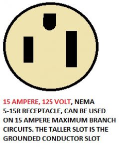
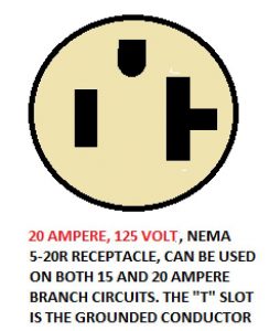
15 Amp, 125 V and 20 Amp, 125 V by Clifford Rutherford are licensed under CC BY 4.0
250 Volt Receptacles
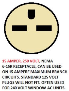
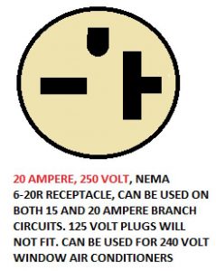
15 Amp, 250 V and 20 Amp, 250 V by Clifford Rutherford are licensed under CC BY 4.0
Receptacle Installation
When connecting circuit conductors to a receptacle (or switch):
Form terminal loops in the wire, put the loop under a terminal screw, looping the wire around the terminal screw in the direction the screw tightens (clockwise in almost all cases), and tighten the screw the proper amount. A terminal screw that is not tightened properly or a wire not looped properly around a screw will typically be the cause of future problems. Push-in terminations are available but are not as good a termination as a terminal loop termination.
The listing instructions for devices like receptacles and switches normally allow only one wire to be terminated to each terminal screw. However, many electrical boxes containing receptacles or switches could have many circuit conductors requiring connections to the device terminal screws. The best way to make the necessary connections so that only one conductor gets connected to a terminal screw is to use a pigtail.
Once the particular receptacle you are installing is connected to the electrical system, secure it to the device box. Make sure the conductors inside the box are pushed to the back of the device box, leaving enough room to install the receptacle.
Carefully push the receptacle into the device box, checking that the ears on the top and bottom of the receptacle yoke will rest against the sheetrock when the receptacle is installed. Once you have determined that the receptacle ears will rest against the drywall or finish surface properly, attach the receptacle to the device box using the properly sized machine screws. Make sure the receptacle is flush with the wall and straight, then attach the cover.
Duplex Receptacles (3 Wires): The most common type of receptacle used in residential wiring is a duplex receptacle rated for 15 amperes at 125 volts. It consists of two single receptacles on the same mounting strap. As many of these devices are installed close to ground level, Tamper-Resistant (T-R) receptacles are required in some locations to protect children.
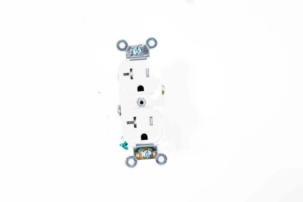
20 Amp Duplex by Bernard Sula is licensed under CC BY 4.0
Ungrounded black conductor– Connected to the brass colored terminal
Grounded white conductor– Connected to the silver screw terminal
Bare or green grounding conductor– Connected to the green grounding screw
How Tamper-Resistant Receptacles Work
Query \(\PageIndex{1}\)
Split-Wired Duplex Receptacle- A split-wired duplex receptacle usually has a switch controlling half of the receptacle and the other half is hot all the time. They are often used to provide an accessible switching device near a doorway that controls a plug-in table lamp across the room (ex: bedside table- split-wire receptacle allows the light to be turned on and off by the doorway, but the alarm clock plugged into the same duplex receptacle remains on at all times). Before installing, remove the tab connecting the terminal screws on the hot side of the receptacle. Do not remove the tab connecting the silver terminal screws.
Ground Fault Circuit Interrupter GFCI- Connect GFCI receptacles to the electrical system in much the same manner as regular duplex receptacles. However, on the back of the GFCI receptacles, one of the brass screw terminals and one of the silver screw terminals are marked for the “Line,” or incoming power conductors. The other set of screw terminals are marked as “Load” terminals, or the outgoing power conductors that protect other receptacles downstream of the GFCI.

GFCI Receptacle by Clifford Rutherford is licensed under CC BY 4.0
Specialty Receptacle Types
Two appliances typically require a special 125/250 volt receptacle installation. These receptacles are larger and have different configurations than the single or duplex receptacles.
125/250 Volt Electric Clothes Dryer
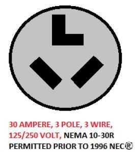
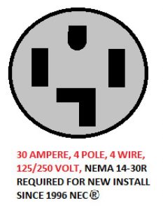
Dryer 30 Amp, 3 Pole and Dryer 30 Amp, 4 Pole by Clifford Rutherford are licensed under CC BY 4.0
125/250 Volt Electric Range
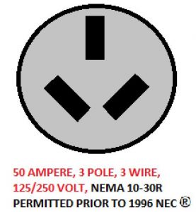
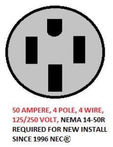
Range 50 Amp, 3 Pole and Range 50 Amp, 4 Pole by Clifford Rutherford are licensed under CC BY 4.0
Switches
Switches are used to control the various lighting accessories, and sometimes receptacles or equipment, installed in residential wiring. The procedures for installing a switch are very similar to receptacle installation procedures. The main difference is the number of switches installed in multi-gang boxes: In residential installations, two- and three-gang switch boxes are common. Take care to ensure there is enough room in the device box for all conductors and switches.
There are two styles of switches commonly used residential and commercial construction: toggle and rocker (also known as decor). While rocker switches are also considered decorative and may be more desirable in some cases, they often have a wider profile than toggle switches and may require more space in the switch box. Because there are so many multi-gang switch boxes, make sure all the switches are level so the faceplate will be level when it is installed.
Switch rating must be matched to the voltage and current you encounter with the circuit on which you are using the switch. Many residential lighting circuits are wired with 14 AWG conductors protected with a 15-amp circuit breaker and will require switches with a 15 amp, 120 volt rating. This switch rating is the most common found in residential wiring.
Single-pole, three-way, and four-way switches are to be wired so that all switching is done in the ungrounded circuit conductor. There is no need to connect a white insulated grounded conductor to any switch in a residential switching circuit.
Single Pole Switch- The single-pole switch used in 120- volt circuits to control a lighting outlet or outlets from only one location is the most common. On a single-pole switch, two wires will be connected to the two terminal screws on the switch. Both wires will be considered “hot” ungrounded conductors.One is the incoming power wire and the other wire runs to the light fixture or receptacle.
- Connect two conductors (usually black or re-identified as such*) to the switch
- Ground the switch.
- Set up the switch so it will read “OFF” when the toggle is in the down position.
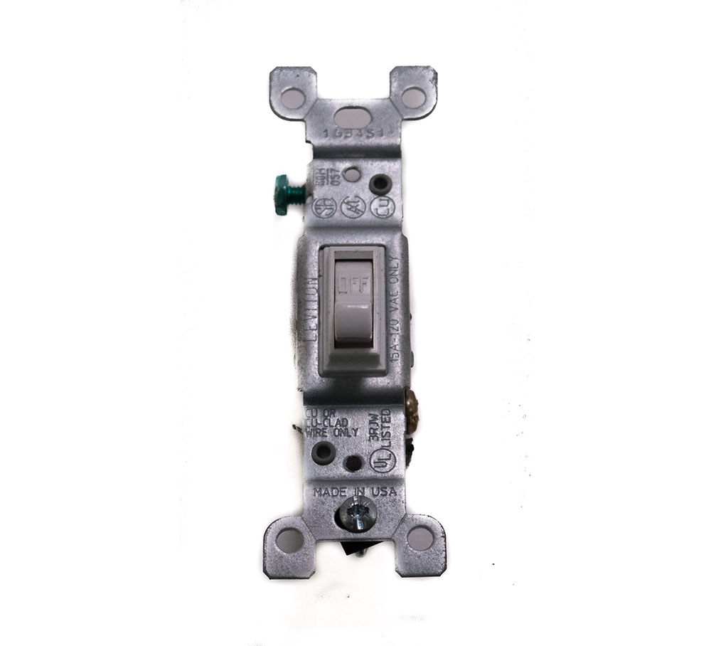
Single Pole Switch by Clifford Rutherford are licensed under CC BY 4.0
*Switch Loop
It is very common for residential electricians to run the power source to the lighting outlet first and then to run a two-wire cable to the single-pole switching location. When employing a switch loop, use the white wire as an ungrounded conductor and identify it as such. It is required that the white conductor be identified at both ends as a hot conductor. Use black electrical tape, although another color tape (like red or blue) may also be used, or a permanent marker to mark the conductor. The mark must completely encircle the conductor.
Three-Way Switch- Connects three conductors to the switch to control a light fixture or receptacle from two locations, such as at the top and bottom of a stairway. Three and four-way switches do not have On/Off markings on them. Beginning electricians and maintenance technicians often find the connections for three-way switches confusing. Learning some basic rules can make the process much easier.
Rules For Three-Way Switches
- Three-way switches must always be installed in pairs.
- A three-wire cable must always be installed between the two three-way switches.
- When wiring with conduit, three separate wires must be pulled into the conduit between the two three-way switches.
- The black colored “common” terminal on a three-way switch should always have a black insulated wire attached to it.
- One three-way switch will have a black “hot” feed conductor attached to it.
- The other three-way switch will have the black insulated conductor that will be going to the lighting load attached to it.
- Connect the two traveler conductors to the two brass colored “traveler” terminals and the conductor that provides power.
- When using nonmetallic sheathed cable:
- When the power source feed is brought to the first three-way switch, the traveler wires that interconnect the traveler terminals of both switches will be black and red.
- When the power source feed is brought to the lighting outlet first, the traveler wires will be red and white.
- Re-identify the white traveler conductors with black tape at each switch location.
- Ground the switch.
Four-Way Switch- Four-way switches have four conductors connected to them. Four-way switches are used in 120-volt circuits to control a lighting load from three or more locations, such as in a room with three doorways that calls for switches controlling the room lighting to be located at each doorway. They are used in conjunction with two three-way switches. Two conductors will come from one three-wire cable and two conductors will come from a second three-wire cable.
- Connect the conductors from one cable to the two screw terminals that are the same color (traveler terminal screws).
- Connect the remaining two conductors to the two screw terminals that are a different color (traveler terminal screws).
Double-Pole Switch- These switches are used on 240-volt circuits to control a load from one location (ex: electric water heater). The double-pole switch has four terminals on it and, at first glance, looks like a four-way switch. Unlike a four-way (or three-way) switch, the toggle on the double-pole switch does have the words “ON” and “OFF” written on it. This means that like a single-pole switch, there is a correct mounting position for the switch so when it is “ON”, the toggle will indicate it. The double-pole switch also has markings that usually indicate the “load” and the “line” sides of the switch. Usually the “line” set of terminals is colored black and the “load” set of terminals is colored a brass or bronze.
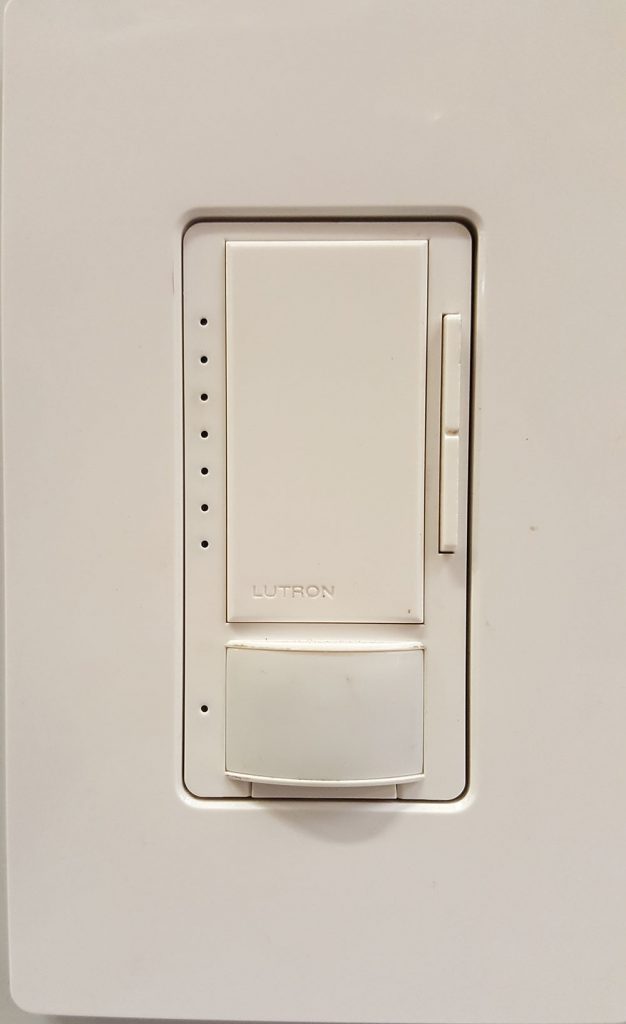
Dimmer Switches- are used to brighten or dim a lighting fixture’s lamps. Found in both a singlepole and a three-way configurations, both are available with either a rotating knob style or sliding
switch that varies the resistance in the circuit. Dimmer switches differ from regular switches in that they do not have terminal screws, but instead have colored insulated pigtail wires coming off the switch installed by the manufacturer. To install a dimmer switch, connect the dimmer switch pigtails to the appropriate circuit conductor with a wirenut. Single-pole or three-way dimmer switches are connected in a switching circuits exactly as regular single pole and three-way switches.
 |
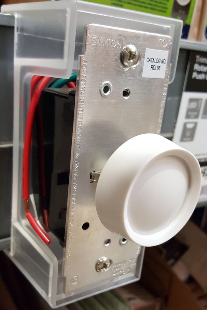 |
Slide Dimmer & Rotary Dimmer by Clifford and Rosemary Rutherford are licensed under CC BY 4.0
Combination Devices
Combination devices have a combination of two devices, both of which are mounted on the same strap. There could be two single-pole switches, a single-pole switch and a three-way switch, a single-pole switch and a receptacle, or a single-pole switch with an indicator light.
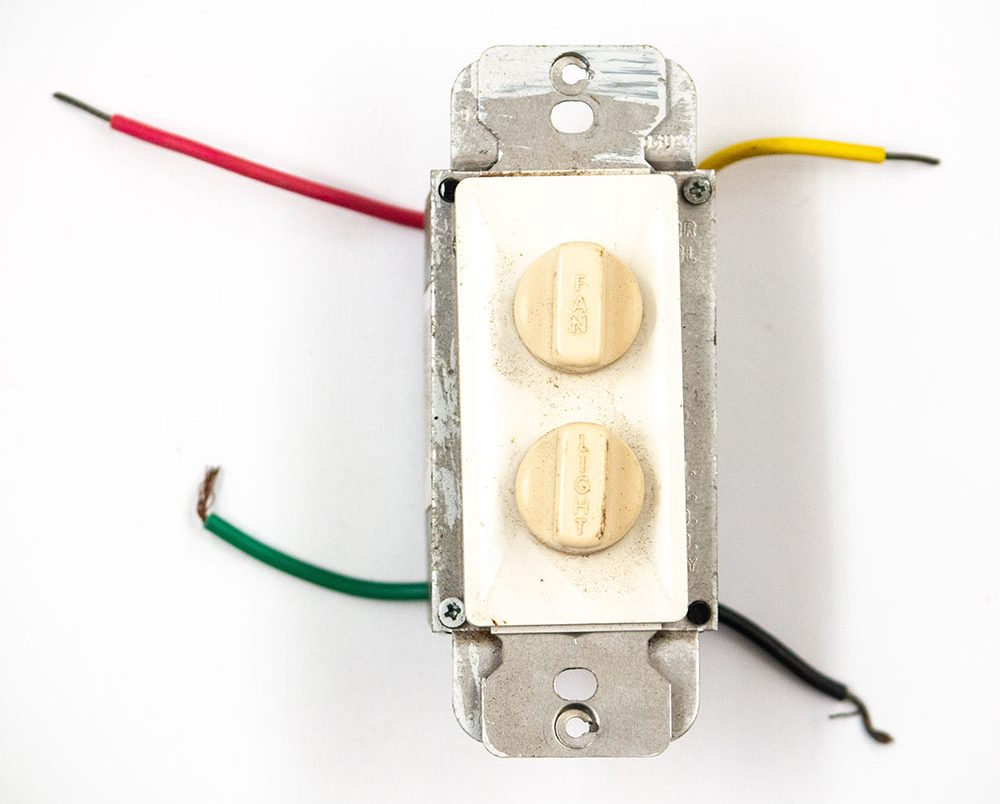
Combination Switch by Gwen Arkin are licensed under CC BY 4.0