
3.4: Module 15- Surface Modeling – Part 4
- Page ID
- 19952

\( \newcommand{\vecs}[1]{\overset { \scriptstyle \rightharpoonup} {\mathbf{#1}} } \)
\( \newcommand{\vecd}[1]{\overset{-\!-\!\rightharpoonup}{\vphantom{a}\smash {#1}}} \)
\( \newcommand{\id}{\mathrm{id}}\) \( \newcommand{\Span}{\mathrm{span}}\)
( \newcommand{\kernel}{\mathrm{null}\,}\) \( \newcommand{\range}{\mathrm{range}\,}\)
\( \newcommand{\RealPart}{\mathrm{Re}}\) \( \newcommand{\ImaginaryPart}{\mathrm{Im}}\)
\( \newcommand{\Argument}{\mathrm{Arg}}\) \( \newcommand{\norm}[1]{\| #1 \|}\)
\( \newcommand{\inner}[2]{\langle #1, #2 \rangle}\)
\( \newcommand{\Span}{\mathrm{span}}\)
\( \newcommand{\id}{\mathrm{id}}\)
\( \newcommand{\Span}{\mathrm{span}}\)
\( \newcommand{\kernel}{\mathrm{null}\,}\)
\( \newcommand{\range}{\mathrm{range}\,}\)
\( \newcommand{\RealPart}{\mathrm{Re}}\)
\( \newcommand{\ImaginaryPart}{\mathrm{Im}}\)
\( \newcommand{\Argument}{\mathrm{Arg}}\)
\( \newcommand{\norm}[1]{\| #1 \|}\)
\( \newcommand{\inner}[2]{\langle #1, #2 \rangle}\)
\( \newcommand{\Span}{\mathrm{span}}\) \( \newcommand{\AA}{\unicode[.8,0]{x212B}}\)
\( \newcommand{\vectorA}[1]{\vec{#1}} % arrow\)
\( \newcommand{\vectorAt}[1]{\vec{\text{#1}}} % arrow\)
\( \newcommand{\vectorB}[1]{\overset { \scriptstyle \rightharpoonup} {\mathbf{#1}} } \)
\( \newcommand{\vectorC}[1]{\textbf{#1}} \)
\( \newcommand{\vectorD}[1]{\overrightarrow{#1}} \)
\( \newcommand{\vectorDt}[1]{\overrightarrow{\text{#1}}} \)
\( \newcommand{\vectE}[1]{\overset{-\!-\!\rightharpoonup}{\vphantom{a}\smash{\mathbf {#1}}}} \)
\( \newcommand{\vecs}[1]{\overset { \scriptstyle \rightharpoonup} {\mathbf{#1}} } \)
\( \newcommand{\vecd}[1]{\overset{-\!-\!\rightharpoonup}{\vphantom{a}\smash {#1}}} \)
\(\newcommand{\avec}{\mathbf a}\) \(\newcommand{\bvec}{\mathbf b}\) \(\newcommand{\cvec}{\mathbf c}\) \(\newcommand{\dvec}{\mathbf d}\) \(\newcommand{\dtil}{\widetilde{\mathbf d}}\) \(\newcommand{\evec}{\mathbf e}\) \(\newcommand{\fvec}{\mathbf f}\) \(\newcommand{\nvec}{\mathbf n}\) \(\newcommand{\pvec}{\mathbf p}\) \(\newcommand{\qvec}{\mathbf q}\) \(\newcommand{\svec}{\mathbf s}\) \(\newcommand{\tvec}{\mathbf t}\) \(\newcommand{\uvec}{\mathbf u}\) \(\newcommand{\vvec}{\mathbf v}\) \(\newcommand{\wvec}{\mathbf w}\) \(\newcommand{\xvec}{\mathbf x}\) \(\newcommand{\yvec}{\mathbf y}\) \(\newcommand{\zvec}{\mathbf z}\) \(\newcommand{\rvec}{\mathbf r}\) \(\newcommand{\mvec}{\mathbf m}\) \(\newcommand{\zerovec}{\mathbf 0}\) \(\newcommand{\onevec}{\mathbf 1}\) \(\newcommand{\real}{\mathbb R}\) \(\newcommand{\twovec}[2]{\left[\begin{array}{r}#1 \\ #2 \end{array}\right]}\) \(\newcommand{\ctwovec}[2]{\left[\begin{array}{c}#1 \\ #2 \end{array}\right]}\) \(\newcommand{\threevec}[3]{\left[\begin{array}{r}#1 \\ #2 \\ #3 \end{array}\right]}\) \(\newcommand{\cthreevec}[3]{\left[\begin{array}{c}#1 \\ #2 \\ #3 \end{array}\right]}\) \(\newcommand{\fourvec}[4]{\left[\begin{array}{r}#1 \\ #2 \\ #3 \\ #4 \end{array}\right]}\) \(\newcommand{\cfourvec}[4]{\left[\begin{array}{c}#1 \\ #2 \\ #3 \\ #4 \end{array}\right]}\) \(\newcommand{\fivevec}[5]{\left[\begin{array}{r}#1 \\ #2 \\ #3 \\ #4 \\ #5 \\ \end{array}\right]}\) \(\newcommand{\cfivevec}[5]{\left[\begin{array}{c}#1 \\ #2 \\ #3 \\ #4 \\ #5 \\ \end{array}\right]}\) \(\newcommand{\mattwo}[4]{\left[\begin{array}{rr}#1 \amp #2 \\ #3 \amp #4 \\ \end{array}\right]}\) \(\newcommand{\laspan}[1]{\text{Span}\{#1\}}\) \(\newcommand{\bcal}{\cal B}\) \(\newcommand{\ccal}{\cal C}\) \(\newcommand{\scal}{\cal S}\) \(\newcommand{\wcal}{\cal W}\) \(\newcommand{\ecal}{\cal E}\) \(\newcommand{\coords}[2]{\left\{#1\right\}_{#2}}\) \(\newcommand{\gray}[1]{\color{gray}{#1}}\) \(\newcommand{\lgray}[1]{\color{lightgray}{#1}}\) \(\newcommand{\rank}{\operatorname{rank}}\) \(\newcommand{\row}{\text{Row}}\) \(\newcommand{\col}{\text{Col}}\) \(\renewcommand{\row}{\text{Row}}\) \(\newcommand{\nul}{\text{Nul}}\) \(\newcommand{\var}{\text{Var}}\) \(\newcommand{\corr}{\text{corr}}\) \(\newcommand{\len}[1]{\left|#1\right|}\) \(\newcommand{\bbar}{\overline{\bvec}}\) \(\newcommand{\bhat}{\widehat{\bvec}}\) \(\newcommand{\bperp}{\bvec^\perp}\) \(\newcommand{\xhat}{\widehat{\xvec}}\) \(\newcommand{\vhat}{\widehat{\vvec}}\) \(\newcommand{\uhat}{\widehat{\uvec}}\) \(\newcommand{\what}{\widehat{\wvec}}\) \(\newcommand{\Sighat}{\widehat{\Sigma}}\) \(\newcommand{\lt}{<}\) \(\newcommand{\gt}{>}\) \(\newcommand{\amp}{&}\) \(\definecolor{fillinmathshade}{gray}{0.9}\)Module 15: Surface Modeling – Part 4
Learning Outcomes
When you have completed this module, you will be able to:
- Describe a 3D polyline and how it compares to a 2D polyline.
- Apply the 3DPOLY command and draw 3D polylines.
- Apply the EDGESURF command.
- Apply the PEDIT, SURFTYPE, SPLFRAME, SURFV, and SURFU commands and system variables to modify the appearance of 3D meshes.
3D Polylines
Since the release of AutoCAD 14, polylines created with the PLINE command have been created as lightweight polylines. Sometimes called a 2D polylines, shown in Figure 15-1, lightweight polyline are greatly improved over the older heavyweight or 3D polylines. A 2D polyline must lay on a single plane.
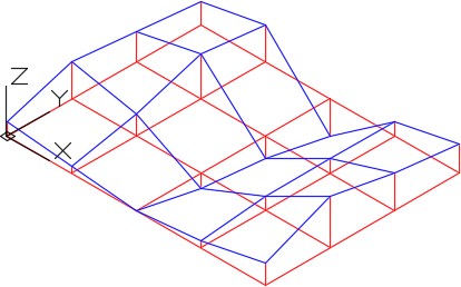
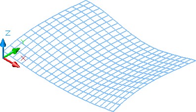
A 3D polyline is created with the 3DPOLY command using XYZ coordinates to locate each of the vertices. See Figure 15-2. A 3D polyline is not restricted to lay on the same plane. It requires a larger part of the drawings database compared to a 2D polyline. For that reason, use 3D polylines only when absolutely required in 3D modeling. 3D polylines must be constructed with lines only and cannot contain arcs or be given a width.
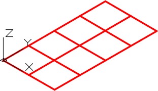
2D polylines
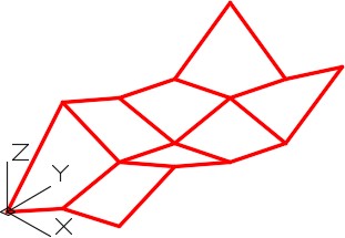
3D polylines
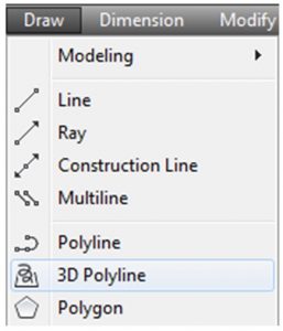
AutoCAD Command: 3DPOLY
The 3DPOLY command is used to create 3D polylines.
Shortcut: none
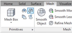
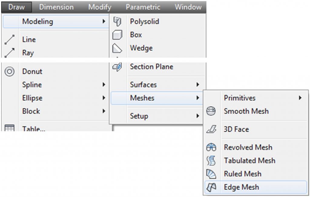
AutoCAD Command: EDGESURF
The EDGESURF command is used to create a surface mesh by selecting four drawing objects. The drawing objects can be lines, arcs, 2D polylines, and 3D polylines.
Shortcut: none
WORK ALONG: Surfacing Models Using 3D Polylines and Edge Surfaces
Step 1
Open the drawing: AutoCAD 3D Workalong 14-1.
Step 2
Using the SAVEAS command, save the drawing with the name: AutoCAD 3D Workalong 15-1.
Step 3
Turn off all layers except layer: Model.
Step 4
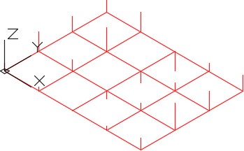
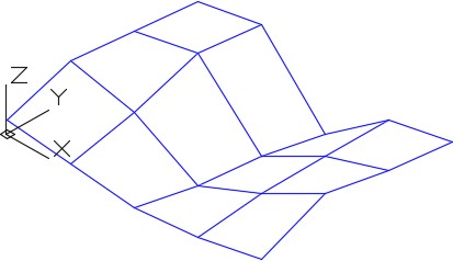
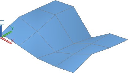
Set the current visual style to 2D Wireframe, the current UCS to World and the current view to SE Isometric. Your model should appear as shown in the figure. (Figure Step 4)
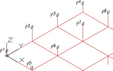
Step 5
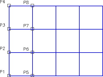
Set layer: 3D Pline as the current layer. Enter the 3DPOLY command, as shown below, to draw 3D polylines between all of the Z coordinates on the grid in both the X and the Y direction. (Figure Step 5)
Command: 3DPOLY
Specify start point of polyline: (end) P1
Specify endpoint of line or [Undo]: (end) P2
Specify endpoint of line or [Undo]: (end) P3
Specify endpoint of line or [Undo]: (end) P4
Specify endpoint of line or [Close/Undo]:
Command: 3DPOLY
Specify start point of polyline: (end) P5
Specify endpoint of line or [Undo]: (end) P6
Specify endpoint of line or [Undo]: (end) P7
Specify endpoint of line or [Undo]: (end) P8
Specify endpoint of line or [Close/Undo]:
Command:
Step 6
Continue drawing the remainder of the 3D polylines on the Y axis. (Figure Step 6)
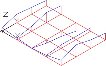
Step 7
Draw 3D polylines between all the Z coordinates in the X direction until you complete the grid. (Figure Step 7)
Step 8
Turn layer: Model off and your model should appear as shown in the figure. Using the EXPLODE command and a window, explode the 3D plines to convert them into lines. (Figure Step 8)
Step 9
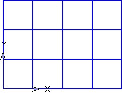
Change the view to Top. (Figure Step 9)
Step 10
Set layer: Surface 1 as the current layer. Enter the 3DMESH command, as shown below, to create the mesh. (Figure Step 10)
Command: 3DMESH
Enter size of mesh in M direction: 5
Enter size of mesh in N direction: 4
Specify location for vertex (0, 0): (end) P1
Specify location for vertex (0, 1): (end) P2
Specify location for vertex (0, 2): (end) P3
Specify location for vertex (0, 3): (end) P4
Specify location for vertex (1, 0): (end) P5
Specify location for vertex (1, 1): (end) P6
Specify location for vertex (1, 2): (end) P7
Specify location for vertex (1, 3): (end) P8
(Continue to cover the complete mesh.)
Command:
Step 11
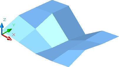
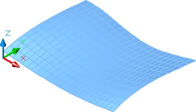
Set the current visual style to Realistic and the current view to SE Isometric. (Figure Step 11)
Step 12
Set the current visual style to 2D Wireframe and turn layer: Surface 1 off. You will only see the 3D polylines. (Figure Step 12)
Step 13
Set the system variables SURFTAB1 to 6 and SURFTAB2 to 6.
Step 14
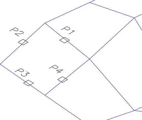
On layer: Surface 4, use the EDGESURF command, as shown below, to create a surface mesh on one grid square. (Figure Step 14)
Command: EDGESURF
Current wire frame density: SURFTAB1=6 SURFTAB2=6
Select object 1 for surface edge: P1
Select object 2 for surface edge: P2
Select object 3 for surface edge: P3
Select object 4 for surface edge: P4
Command:
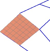
Step 15
Set the current visual style to Realistic. (Figure Step 15)
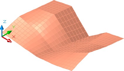
Step 16
On layer: Surface 4, using the EDGESURF command, create surfaces in all grid squares to cover the model. When complete, the model will appear as shown in the figure. (Figure Step 16)
Step 17
Save and close the drawing.
Modifying the Appearance of Surface Meshes
There are several system variables that can be used to modify or change the appearance of existing surface meshes or changing their mesh density. The PEDIT command and SURFV, SURFU, SURFTYPE, and SPLFRAME system variables are used to smooth and change the setting for the appearance of and mesh density of 3D meshes. If the desired results cannot be obtained using these system variables, it is sometime easier and faster to erase the surface and construct it again using a smaller base grid.
System Variable: SURFV and SURFU
The SURFV and SURFU system variables are used to set the surface mesh density of the M and N directions when the Smooth option is selected in the PEDIT command.
Shortcut: none
SURFU sets the M direction.
SURFV sets the N direction.
System Variable: SURFTYPE
The SURFTYPE system variable is used to control the method AutoCAD fits the surface when the Smooth option is selected in the PEDIT command.
Shortcut: none
It has the following settings:
5 – Quadratic B-spline surface
6 – Cubic B-spline surface
8 – Bezier surface
System Variable: SPLFRAME
The SPLFRAME command is used to control the display of splines and meshes that have been smoothed.
Shortcut: none
It has the following settings:
0 – Enables the display of the smoothed meshes and spline-fit
1 – Disables the display of the smoothed meshes or spline-fit It will display the original mesh. It does not display the invisible edges of 3D faces or polyface meshes.
WORK ALONG: Modifying the Appearance of Surface Meshes
Step 1
Open drawing: AutoCAD 3D Workalong 15-1. Using the SAVEAS command, save the drawing with the name: AutoCAD 3D Workalong 15-2.
Step 2
Turn off all layers except layer: Surface 1. Set the current visual style to Realistic, the current UCS to World and the current view to SE Isometric. (Figure Step 2)
Step 3
Set the current visual style to 3D Wireframe. (Figure Step 3)

Step 4
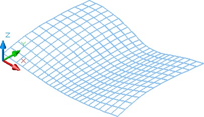
Enter the commands shown below and your model will appear as shown in the figure. (Figure Step 4)
Command: SURFV
Enter new value for SURFV <6>: 12
Command: SURFU
Enter new value for SURFU <6>: 24
Command: PEDIT
Select polyline or [Multiple]:
(Select the mesh.)
Enter an option [Edit vertex/Smooth surface/Desmooth/Mclose/Nclose/Undo]: S
Generating segment 2… Command: REGEN
REGEN Regenerating model.
Command:
Step 5
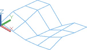
Enter the commands shown below. The model should display as it was when you started this exercise. (Figure Step 5)
Command: SPLFRAME
Enter new value for SPLFRAME <0>: 1
Command: REGEN Regenerating model.
Command:
Step 6
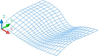
Enter the commands shown below and your model will display as shown in the figure. (Figure Step 6)
Command: SPLFRAME
Enter new value for SPLFRAME <1>: 0
Command: REGEN
Regenerating model
Command:

Step 7
Enter the commands shown below and your model will display as shown in the figure. (Figure Step 7)
Command: SURFTYPE
Enter new value for SURFTYPE <6>: 5
Command: PEDIT
Select polyline or [Multiple]:
(Select the mesh.)
Enter an option [Smooth surface/Desmooth/MOpen/MClose/NOpen/NClose/Undo]: S
Command:
Step 8
Enter the commands shown below and your model will display as shown in the figure. (Figure Step 8)
Command: SURFTYPE
Enter new value for SURFTYPE <5: 8
Command: PEDIT
Select polyline or [Multiple]:
(Select the mesh.)
Enter an option [Smooth surface/Desmooth/MOpen/MClose/NOpen/NClose/Undo]: S
Command:
Step 9
Set the current visual style to Realistic. (Figure Step 9)
Step 10
Save and close the drawing.
Key Principles
The Key Principles in Module 15
- Sometimes called a 2D polyline, a lightweight polyline is greatly improved over the older heavyweight or 3D A 2D polyline must lay on a single plane.
- A 3D polyline is created with the 3DPOLY command using XYZ coordinates to locate each A 3D polyline is not restricted to lay on the same plane.
- The command PEDIT and system variables SURFV, SURFU, SURFTYPE, and SPLFRAME are used to smooth and change the setting for the appearance of and mesh density of 3D meshes.
Lab Exercise 15-1
Time allowed: 3 hours.
| Drawing Name | Template | Units |
|---|---|---|
| AutoCAD 3D Lab 15-1 | 3D Layout English | Feet |
Step 1
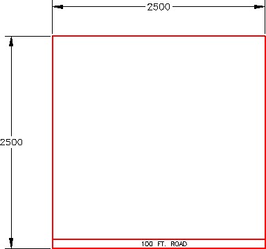
In this lab exercise, you will be creating a surface mesh on a plot of land that is 2500 X 2500 feet. There is an exiting 100 ft. road on the south side of the property. (Figure Step 1)
Step 2
Start a new drawing, using the template 3D Layout English. Insert the block: AutoCAD 3D Lab 15-1. Explode the block.
Step 3
Change the layer of all objects to layer: Model. (Figure Step 3)
Step 4
Change the current view to SE Isometric. (Figure Step 4)
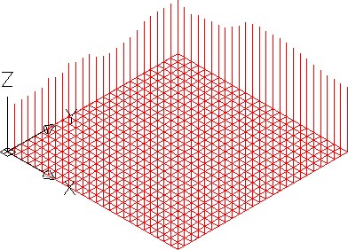
Step 5
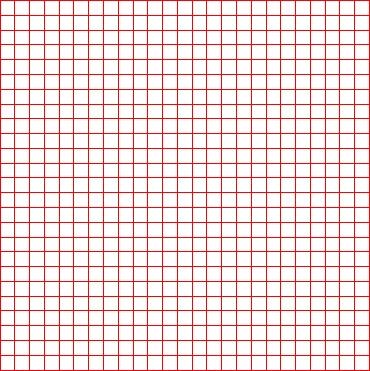
The 2D grid is located at sea level or Z=zero and is divided equally every 100 ft.
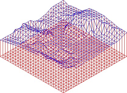
Step 6
On the layer: 3D Pline, draw 3D polylines between the top of each of the Z coordinate lines to construct a digital terrain model of the property as shown below. Try rotating the grid and lines to different positions to find the best view to insert the 3D polylines. (Figure Step 6)
Step 7
Turn off all layers except layers: 3D Pline and Surface 2.
Step 8
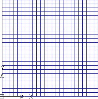
Change the view to Top. (Figure Step 8)
Step 9
Set layer: Surface 2 as the current layer. Using the EXPLODE command and a window, explode the 3D plines to convert them into lines.
Step 10
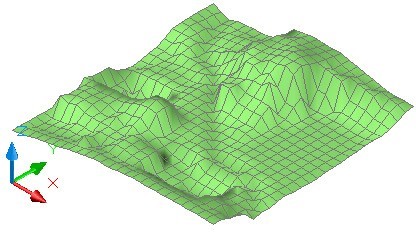
Using the 3DMESH command, draw a mesh by snapping to each of the 625 endpoints. Ensure to select the points in the correct sequence and zoom in to select very accurately. If an error is made, start over again. This will require about 30 minutes of uninterrupted work. Turn layer: 3D Pline off. Set the current view to SE Isometric and the current visual style to Realistic. (Figure Step 10)
Step 11
Save and close the drawing.