3.5: Module 16 Competency Test No.3 Open Book
- Page ID
- 19953

\( \newcommand{\vecs}[1]{\overset { \scriptstyle \rightharpoonup} {\mathbf{#1}} } \)
\( \newcommand{\vecd}[1]{\overset{-\!-\!\rightharpoonup}{\vphantom{a}\smash {#1}}} \)
\( \newcommand{\id}{\mathrm{id}}\) \( \newcommand{\Span}{\mathrm{span}}\)
( \newcommand{\kernel}{\mathrm{null}\,}\) \( \newcommand{\range}{\mathrm{range}\,}\)
\( \newcommand{\RealPart}{\mathrm{Re}}\) \( \newcommand{\ImaginaryPart}{\mathrm{Im}}\)
\( \newcommand{\Argument}{\mathrm{Arg}}\) \( \newcommand{\norm}[1]{\| #1 \|}\)
\( \newcommand{\inner}[2]{\langle #1, #2 \rangle}\)
\( \newcommand{\Span}{\mathrm{span}}\)
\( \newcommand{\id}{\mathrm{id}}\)
\( \newcommand{\Span}{\mathrm{span}}\)
\( \newcommand{\kernel}{\mathrm{null}\,}\)
\( \newcommand{\range}{\mathrm{range}\,}\)
\( \newcommand{\RealPart}{\mathrm{Re}}\)
\( \newcommand{\ImaginaryPart}{\mathrm{Im}}\)
\( \newcommand{\Argument}{\mathrm{Arg}}\)
\( \newcommand{\norm}[1]{\| #1 \|}\)
\( \newcommand{\inner}[2]{\langle #1, #2 \rangle}\)
\( \newcommand{\Span}{\mathrm{span}}\) \( \newcommand{\AA}{\unicode[.8,0]{x212B}}\)
\( \newcommand{\vectorA}[1]{\vec{#1}} % arrow\)
\( \newcommand{\vectorAt}[1]{\vec{\text{#1}}} % arrow\)
\( \newcommand{\vectorB}[1]{\overset { \scriptstyle \rightharpoonup} {\mathbf{#1}} } \)
\( \newcommand{\vectorC}[1]{\textbf{#1}} \)
\( \newcommand{\vectorD}[1]{\overrightarrow{#1}} \)
\( \newcommand{\vectorDt}[1]{\overrightarrow{\text{#1}}} \)
\( \newcommand{\vectE}[1]{\overset{-\!-\!\rightharpoonup}{\vphantom{a}\smash{\mathbf {#1}}}} \)
\( \newcommand{\vecs}[1]{\overset { \scriptstyle \rightharpoonup} {\mathbf{#1}} } \)
\( \newcommand{\vecd}[1]{\overset{-\!-\!\rightharpoonup}{\vphantom{a}\smash {#1}}} \)
\(\newcommand{\avec}{\mathbf a}\) \(\newcommand{\bvec}{\mathbf b}\) \(\newcommand{\cvec}{\mathbf c}\) \(\newcommand{\dvec}{\mathbf d}\) \(\newcommand{\dtil}{\widetilde{\mathbf d}}\) \(\newcommand{\evec}{\mathbf e}\) \(\newcommand{\fvec}{\mathbf f}\) \(\newcommand{\nvec}{\mathbf n}\) \(\newcommand{\pvec}{\mathbf p}\) \(\newcommand{\qvec}{\mathbf q}\) \(\newcommand{\svec}{\mathbf s}\) \(\newcommand{\tvec}{\mathbf t}\) \(\newcommand{\uvec}{\mathbf u}\) \(\newcommand{\vvec}{\mathbf v}\) \(\newcommand{\wvec}{\mathbf w}\) \(\newcommand{\xvec}{\mathbf x}\) \(\newcommand{\yvec}{\mathbf y}\) \(\newcommand{\zvec}{\mathbf z}\) \(\newcommand{\rvec}{\mathbf r}\) \(\newcommand{\mvec}{\mathbf m}\) \(\newcommand{\zerovec}{\mathbf 0}\) \(\newcommand{\onevec}{\mathbf 1}\) \(\newcommand{\real}{\mathbb R}\) \(\newcommand{\twovec}[2]{\left[\begin{array}{r}#1 \\ #2 \end{array}\right]}\) \(\newcommand{\ctwovec}[2]{\left[\begin{array}{c}#1 \\ #2 \end{array}\right]}\) \(\newcommand{\threevec}[3]{\left[\begin{array}{r}#1 \\ #2 \\ #3 \end{array}\right]}\) \(\newcommand{\cthreevec}[3]{\left[\begin{array}{c}#1 \\ #2 \\ #3 \end{array}\right]}\) \(\newcommand{\fourvec}[4]{\left[\begin{array}{r}#1 \\ #2 \\ #3 \\ #4 \end{array}\right]}\) \(\newcommand{\cfourvec}[4]{\left[\begin{array}{c}#1 \\ #2 \\ #3 \\ #4 \end{array}\right]}\) \(\newcommand{\fivevec}[5]{\left[\begin{array}{r}#1 \\ #2 \\ #3 \\ #4 \\ #5 \\ \end{array}\right]}\) \(\newcommand{\cfivevec}[5]{\left[\begin{array}{c}#1 \\ #2 \\ #3 \\ #4 \\ #5 \\ \end{array}\right]}\) \(\newcommand{\mattwo}[4]{\left[\begin{array}{rr}#1 \amp #2 \\ #3 \amp #4 \\ \end{array}\right]}\) \(\newcommand{\laspan}[1]{\text{Span}\{#1\}}\) \(\newcommand{\bcal}{\cal B}\) \(\newcommand{\ccal}{\cal C}\) \(\newcommand{\scal}{\cal S}\) \(\newcommand{\wcal}{\cal W}\) \(\newcommand{\ecal}{\cal E}\) \(\newcommand{\coords}[2]{\left\{#1\right\}_{#2}}\) \(\newcommand{\gray}[1]{\color{gray}{#1}}\) \(\newcommand{\lgray}[1]{\color{lightgray}{#1}}\) \(\newcommand{\rank}{\operatorname{rank}}\) \(\newcommand{\row}{\text{Row}}\) \(\newcommand{\col}{\text{Col}}\) \(\renewcommand{\row}{\text{Row}}\) \(\newcommand{\nul}{\text{Nul}}\) \(\newcommand{\var}{\text{Var}}\) \(\newcommand{\corr}{\text{corr}}\) \(\newcommand{\len}[1]{\left|#1\right|}\) \(\newcommand{\bbar}{\overline{\bvec}}\) \(\newcommand{\bhat}{\widehat{\bvec}}\) \(\newcommand{\bperp}{\bvec^\perp}\) \(\newcommand{\xhat}{\widehat{\xvec}}\) \(\newcommand{\vhat}{\widehat{\vvec}}\) \(\newcommand{\uhat}{\widehat{\uvec}}\) \(\newcommand{\what}{\widehat{\wvec}}\) \(\newcommand{\Sighat}{\widehat{\Sigma}}\) \(\newcommand{\lt}{<}\) \(\newcommand{\gt}{>}\) \(\newcommand{\amp}{&}\) \(\definecolor{fillinmathshade}{gray}{0.9}\)Module 16 Competency Test No.3 Open Book
Learning Outcomes
When you have completed this module, you will be able to:
- Within a five hour time limit, complete a written exam and the lab exercises without the aid of a key.
The AutoCAD 3D book was written with competency based modules. What that means is that you have not completed each module until you have mastered it. The Competency Test module contains multiple choice questions and a comprehensive lab exercise to test your mastery of the set of modules that you completed. There are no answers or keys supplied in a Competency Test module since it is meant to be checked by your instructor. If there are any parts of this module that you have trouble completing, you should go back and reread the module or modules containing the information that you are having trouble with. If necessary, redo as many lab exercises required until you fully understand the material.
If you are completing this book:
- Without the aid of an instructor, complete the written test and the lab exercise.
- In a classroom with an instructor, the instructor will give instructions on what to do after this module has been completed.
Multiple Choice Questions
Select the BEST answer.
- In a surface mesh, what is the intersection of a column and a row called?
- Crossing
- Point
- Junction
- Corner
- Vertex
- What command creates a surface mesh by selecting 4 edges?
- EDGE
- EDGESURF
- REVSURF
- TABSURF
- RULESURF
- What system variable(s) controls the surface mesh density of the M and N directions when a surface mesh is smoothed with the PEDIT command?
- SURFMESH
- SURFTAB1 and SURTAB2
- SPLFRAME
- SURFV and SURFU
- SURFTYPE
- What type of AutoCAD object is a two-dimensional solid created within a closed object? Choose the BEST answer.
- Wireframe
- Mesh
- Region
- Surface
- Solid
- A mesh is defined by rows and columns. What are the columns called?
- M
- S
- R
- C
- N
- What command creates a mesh from a path curve along a direction vector?
- 3DMESH
- EDGE
- 3DFACE
- REVSURF
- TABSURF
- What system variable(s) controls the mesh density of a surface mesh when the mesh is created?
- SURFMESH
- SURFTAB1 and SURTAB2
- SPLFRAME
- SURFV and SURFU
- SURFTYPE
- What command creates a surface face bounded by a minimum of three and a maximum of four edges?
- 3DMESH
- EDGE
- 3DFACE
- REVSURF
- TABSURF
- What system variable(s) controls the display of splines and meshes that have been smoothed with the PEDIT command?.
- SURFMESH
- SURFTAB1 and SURTAB2
- SPLFRAME
- SURFV and SURFU
- SURFTYPE
- What command creates an irregular complex surface mesh from a grid of XYZ coordinates?
- 3DMESH
- EDGE
- 3DFACE
- REVSURF
- TABSURF
Lab Exercise 16-1A OPEN BOOK
| Drawing Name | Template | Units |
|---|---|---|
| AutoCAD 3D Lab 16-1A | 3D Layout English | Inches |
Step 1
On layer: Model, draw a wireframe model of the Base. (Figure Step 1)
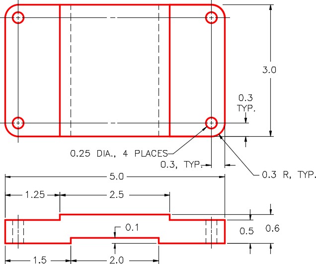
Dimensioned Multiview Drawing of the Base
Step 2
On layer: Surface Base, surface the complete model. Use faces, meshes, regions, or a mixture of them. (Figure Step 2)
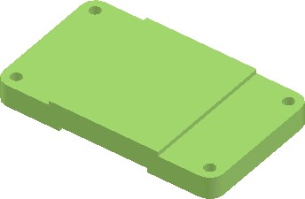
Surfaced Model of the Base
Step 3
Create a block of the model. Name it: AutoCAD 3D Lab 16-1A. Pick an appropriate location for 0,0,0. Make 0,0,0 as the insert point for the block. Ensure that the current UCS is located at the World when creating the block.
Lab Exercise 16-1B OPEN BOOK
| Drawing Name | Template | Units |
|---|---|---|
| AutoCAD 3D Lab 16-1B | 3D Layout English | Inches |
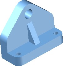
Step 1
On layer: Model, draw a wireframe model of the Support. (Figure Step 1)
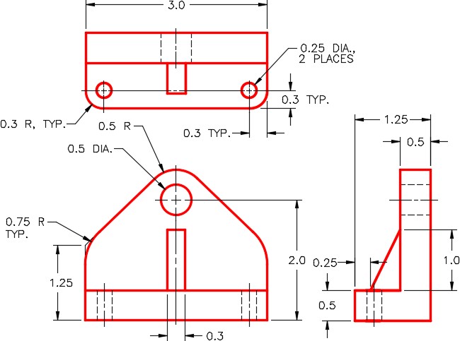
Dimensioned Multiview Drawing of the Support
Step 2
On layer: Construction, add any necessary construction objects that may help insert the model into the assembly.
Step 3
On layer: Surface Support, surface the complete model. Use faces, meshes, regions, or a mixture of them. (Figure Step 3)
Step 4
Create a block of the model. Name it:
AutoCAD 3D Lab 16-1B. Pick an appropriate location for 0,0,0. Make 0,0,0 as the insert point for the block. Ensure that the current UCS is located at the World when creating the block.
Lab Exercise 16-1C OPEN BOOK
| Drawing Name | Template | Units |
|---|---|---|
| AutoCAD 3D Lab 16-1C | 3D Layout English | Inches |
Step 1
On layer: Model, draw a wireframe model of the Axel. (Figure Step 1)
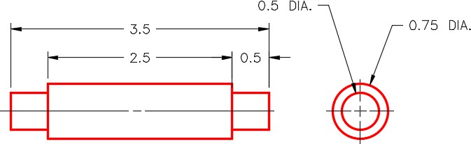
Dimensioned Multiview Drawing of the Axle
Step 2
On layer: Construction, add any necessary construction objects that may help insert the model into the assembly.
Step 3
On layer: Surface Axel, surface the complete model. Use faces, meshes, regions, or a mixture of them. (Figure Step 3)
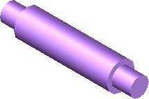
Surfaced Model of the Axle
Step 4
Create a block of the model. Name it:
AutoCAD 3D Lab 16-1C. Pick an appropriate location for 0,0,0. Make 0,0,0 as the insert point for the block. Ensure that the current UCS is located at the World when creating the block.
Lab Exercise 16-1D OPEN BOOK
| Drawing Name | Template | Units |
|---|---|---|
| AutoCAD 3D Lab 16-1D | 3D Layout English | Inches |
Step 1
on layer Model, draw a wireframe model of the Wheel. (Figure Step 1)
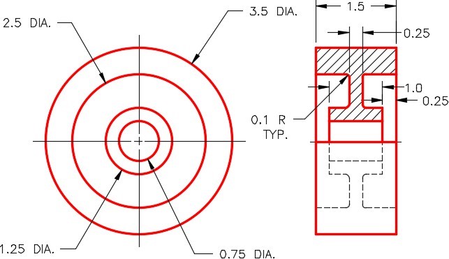
Dimensioned Multiview Drawing of the Wheel
Step 2
On layer Construction, add any necessary construction objects that may help insert the model into the assembly.
Step 3
On layer Surface Wheel, surface the complete model. Use faces, meshes, regions, or a mixture of them. (Figure Step 3)
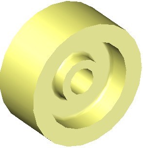
Surfaced Model of the Wheel
Step 4
Create a block of the model. Name it:
AutoCAD 3D Lab 16-1D. Pick an appropriate location for 0,0,0. Make 0,0,0 as the insert point for the block. Ensure that the current UCS is located at the World when creating the block.
Lab Exercise 16-1E OPEN BOOK
| Drawing Name | Template | Units |
|---|---|---|
| AutoCAD 3D Lab 16-1E | 3D Layout English | Inches |
Step 1
On layer: Model, draw a wireframe model of the Washer. (Figure Step 1)
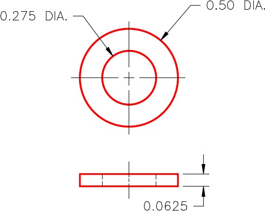
Dimensioned Multiview Drawing of the Washer
Step 2
On layer: Construction, add any necessary construction objects that may help insert the model into the assembly.
Step 3
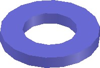
On layer: Surface Washer, surface the complete model. Use faces, meshes, regions, or a mixture of them. (Figure Step 3)
Step 4
Create a block of the model. Name it:
AutoCAD 3D Lab 16-1E. Pick an appropriate location for 0,0,0. Make 0,0,0 as the insert point for the block. Ensure that the current UCS is located at the World when creating the block.
Lab Exercise 16-1F OPEN BOOK
| Drawing Name | Template | Units |
|---|---|---|
| AutoCAD 3D Lab 16-1F | 3D Layout English | Inches |
Step 1
On layer: Model, draw a wireframe model of the Bolt. (Figure Step 1)
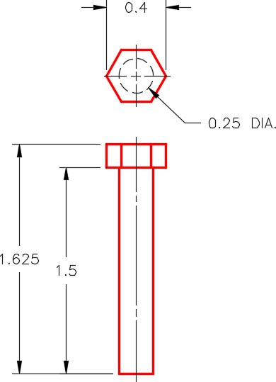
Dimensioned Multiview Drawing of the Bolt
Step 2
On layer: Construction, add any necessary construction objects that may help to insert the model into the assembly.
Step 3
On layer: Surface Bolt, surface the complete model. Use faces, meshes, regions, or a mixture of them. (Figure Step 3)

Surfaced Model of the
Bolt
Step 4
Create a block of the model. Name it:
AutoCAD 3D Lab 16-1F. Pick an appropriate location for 0,0,0. Make 0,0,0 as the insert point for the block. Ensure that the current UCS is located at the World when creating the block.
Lab Exercise 16-1 OPEN BOOK
| Drawing Name | Template | Units |
|---|---|---|
| AutoCAD 3D Lab 16-1 | 3D Layout English | Inches |
Step 1
Start a new drawing and save it with the name: AutoCAD 3D Lab 16-1.
Step 2
Open the six drawings that were created earlier in this lab exercise.
Step 3
Set the UCS to World and using DesignCenter, insert the following blocks into the drawing: AutoCAD 3D Lab 16-1.
1- AutoCAD 3D Lab 16-1A
2- AutoCAD 3D Lab 16-1B
1- AutoCAD 3D Lab 16-1C
1- AutoCAD 3D Lab 16-1D
4- AutoCAD 3D Lab 16-1E
4- AutoCAD 3D Lab 16-1F
Step 4
Close all drawings except for: AutoCAD 3D Lab 16-1
Step 5
Ensure that layers: Model and Construction are on and all surface layers are off. Move the blocks into their exact location to create the assembly using the model or construction objects and object snap to help locate them accurately.
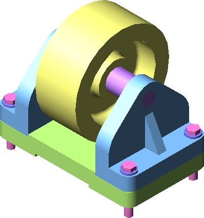
Step 6
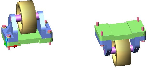
Turn on all surface layers and turn off the layers: Model and Construction. (Figure Step 6)
Step 7
With UCS set to World, copy the complete Caster Assembly 10 inches in the X direction. Rotate the copy of the assembly 180 degrees around the X axis. (Figure Step 7)