
4.1: Module 17- Solid Modeling – Part 1
- Page ID
- 19955

\( \newcommand{\vecs}[1]{\overset { \scriptstyle \rightharpoonup} {\mathbf{#1}} } \)
\( \newcommand{\vecd}[1]{\overset{-\!-\!\rightharpoonup}{\vphantom{a}\smash {#1}}} \)
\( \newcommand{\dsum}{\displaystyle\sum\limits} \)
\( \newcommand{\dint}{\displaystyle\int\limits} \)
\( \newcommand{\dlim}{\displaystyle\lim\limits} \)
\( \newcommand{\id}{\mathrm{id}}\) \( \newcommand{\Span}{\mathrm{span}}\)
( \newcommand{\kernel}{\mathrm{null}\,}\) \( \newcommand{\range}{\mathrm{range}\,}\)
\( \newcommand{\RealPart}{\mathrm{Re}}\) \( \newcommand{\ImaginaryPart}{\mathrm{Im}}\)
\( \newcommand{\Argument}{\mathrm{Arg}}\) \( \newcommand{\norm}[1]{\| #1 \|}\)
\( \newcommand{\inner}[2]{\langle #1, #2 \rangle}\)
\( \newcommand{\Span}{\mathrm{span}}\)
\( \newcommand{\id}{\mathrm{id}}\)
\( \newcommand{\Span}{\mathrm{span}}\)
\( \newcommand{\kernel}{\mathrm{null}\,}\)
\( \newcommand{\range}{\mathrm{range}\,}\)
\( \newcommand{\RealPart}{\mathrm{Re}}\)
\( \newcommand{\ImaginaryPart}{\mathrm{Im}}\)
\( \newcommand{\Argument}{\mathrm{Arg}}\)
\( \newcommand{\norm}[1]{\| #1 \|}\)
\( \newcommand{\inner}[2]{\langle #1, #2 \rangle}\)
\( \newcommand{\Span}{\mathrm{span}}\) \( \newcommand{\AA}{\unicode[.8,0]{x212B}}\)
\( \newcommand{\vectorA}[1]{\vec{#1}} % arrow\)
\( \newcommand{\vectorAt}[1]{\vec{\text{#1}}} % arrow\)
\( \newcommand{\vectorB}[1]{\overset { \scriptstyle \rightharpoonup} {\mathbf{#1}} } \)
\( \newcommand{\vectorC}[1]{\textbf{#1}} \)
\( \newcommand{\vectorD}[1]{\overrightarrow{#1}} \)
\( \newcommand{\vectorDt}[1]{\overrightarrow{\text{#1}}} \)
\( \newcommand{\vectE}[1]{\overset{-\!-\!\rightharpoonup}{\vphantom{a}\smash{\mathbf {#1}}}} \)
\( \newcommand{\vecs}[1]{\overset { \scriptstyle \rightharpoonup} {\mathbf{#1}} } \)
\(\newcommand{\longvect}{\overrightarrow}\)
\( \newcommand{\vecd}[1]{\overset{-\!-\!\rightharpoonup}{\vphantom{a}\smash {#1}}} \)
\(\newcommand{\avec}{\mathbf a}\) \(\newcommand{\bvec}{\mathbf b}\) \(\newcommand{\cvec}{\mathbf c}\) \(\newcommand{\dvec}{\mathbf d}\) \(\newcommand{\dtil}{\widetilde{\mathbf d}}\) \(\newcommand{\evec}{\mathbf e}\) \(\newcommand{\fvec}{\mathbf f}\) \(\newcommand{\nvec}{\mathbf n}\) \(\newcommand{\pvec}{\mathbf p}\) \(\newcommand{\qvec}{\mathbf q}\) \(\newcommand{\svec}{\mathbf s}\) \(\newcommand{\tvec}{\mathbf t}\) \(\newcommand{\uvec}{\mathbf u}\) \(\newcommand{\vvec}{\mathbf v}\) \(\newcommand{\wvec}{\mathbf w}\) \(\newcommand{\xvec}{\mathbf x}\) \(\newcommand{\yvec}{\mathbf y}\) \(\newcommand{\zvec}{\mathbf z}\) \(\newcommand{\rvec}{\mathbf r}\) \(\newcommand{\mvec}{\mathbf m}\) \(\newcommand{\zerovec}{\mathbf 0}\) \(\newcommand{\onevec}{\mathbf 1}\) \(\newcommand{\real}{\mathbb R}\) \(\newcommand{\twovec}[2]{\left[\begin{array}{r}#1 \\ #2 \end{array}\right]}\) \(\newcommand{\ctwovec}[2]{\left[\begin{array}{c}#1 \\ #2 \end{array}\right]}\) \(\newcommand{\threevec}[3]{\left[\begin{array}{r}#1 \\ #2 \\ #3 \end{array}\right]}\) \(\newcommand{\cthreevec}[3]{\left[\begin{array}{c}#1 \\ #2 \\ #3 \end{array}\right]}\) \(\newcommand{\fourvec}[4]{\left[\begin{array}{r}#1 \\ #2 \\ #3 \\ #4 \end{array}\right]}\) \(\newcommand{\cfourvec}[4]{\left[\begin{array}{c}#1 \\ #2 \\ #3 \\ #4 \end{array}\right]}\) \(\newcommand{\fivevec}[5]{\left[\begin{array}{r}#1 \\ #2 \\ #3 \\ #4 \\ #5 \\ \end{array}\right]}\) \(\newcommand{\cfivevec}[5]{\left[\begin{array}{c}#1 \\ #2 \\ #3 \\ #4 \\ #5 \\ \end{array}\right]}\) \(\newcommand{\mattwo}[4]{\left[\begin{array}{rr}#1 \amp #2 \\ #3 \amp #4 \\ \end{array}\right]}\) \(\newcommand{\laspan}[1]{\text{Span}\{#1\}}\) \(\newcommand{\bcal}{\cal B}\) \(\newcommand{\ccal}{\cal C}\) \(\newcommand{\scal}{\cal S}\) \(\newcommand{\wcal}{\cal W}\) \(\newcommand{\ecal}{\cal E}\) \(\newcommand{\coords}[2]{\left\{#1\right\}_{#2}}\) \(\newcommand{\gray}[1]{\color{gray}{#1}}\) \(\newcommand{\lgray}[1]{\color{lightgray}{#1}}\) \(\newcommand{\rank}{\operatorname{rank}}\) \(\newcommand{\row}{\text{Row}}\) \(\newcommand{\col}{\text{Col}}\) \(\renewcommand{\row}{\text{Row}}\) \(\newcommand{\nul}{\text{Nul}}\) \(\newcommand{\var}{\text{Var}}\) \(\newcommand{\corr}{\text{corr}}\) \(\newcommand{\len}[1]{\left|#1\right|}\) \(\newcommand{\bbar}{\overline{\bvec}}\) \(\newcommand{\bhat}{\widehat{\bvec}}\) \(\newcommand{\bperp}{\bvec^\perp}\) \(\newcommand{\xhat}{\widehat{\xvec}}\) \(\newcommand{\vhat}{\widehat{\vvec}}\) \(\newcommand{\uhat}{\widehat{\uvec}}\) \(\newcommand{\what}{\widehat{\wvec}}\) \(\newcommand{\Sighat}{\widehat{\Sigma}}\) \(\newcommand{\lt}{<}\) \(\newcommand{\gt}{>}\) \(\newcommand{\amp}{&}\) \(\definecolor{fillinmathshade}{gray}{0.9}\)Module 17: Solid Modeling – Part 1
Learning Outcomes
When you have completed this module, you will be able to:
- List the six solid primitives.
- Apply the BOX, WEDGE, CYLINDER, UNION, and SUBTRACT commands to draw solid models using solid models using solid primitives.
Solid Modeling
A solid model is the best possible computerized representation of a real object. A solid model is one AutoCAD object. It is a much more complete model then a wireframe or a surfaced model. A solid model, unlike a hollow wireframe or surfaced model, is solid. A solid model can be rendered or shaded plus the mass properties can be obtained from it. Displaying the mass properties is taught in Module 25.
In a lot of ways, constructing a solid model is simpler than constructing a surfaced model. It is important to understand that when you construct solid models, you must still use all of the 3D construction techniques that were taught in the first 16 modules.
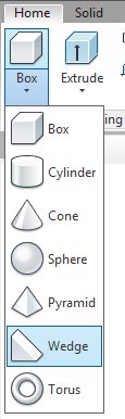
Solid Primitives
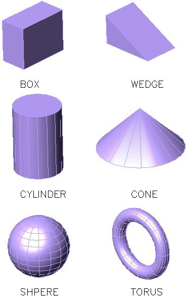
The most basic method of constructing solid models is to create a series of solid primitives and then add them together or subtract them from one another to complete the solid model. Using solid primitives is not the best method of solid modeling but at times they can be a very useful modeling tool. The six primitives are the box, wedge, cylinder, sphere, cone and torus. See Figure 17-1. In this module, you will be constructing solid boxes, wedges, and cylinders.
The next four modules teaches many different commands and techniques used to construct solid models. You can pick and choose how and when to use them to construct each model.
Solid Primitives
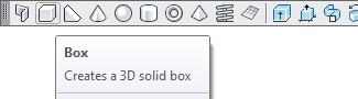
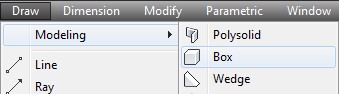
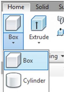
AutoCAD Command: BOX
The BOX command is used to create a solid box primitive.
Shortcut: none
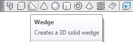
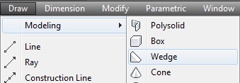
AutoCAD Command: WEDGE
The WEDGE command is used to create a solid wedge primitive.
Shortcut: none
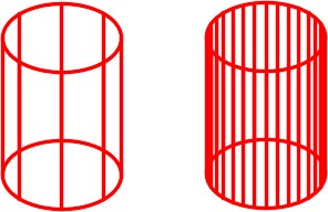
AutoCAD Command: ISOLINES
The ISOLINES system variable is used set the number of contour lines that a curved surface solid model will be constructed with. The valid settings are from 0 to 2047. After you change the setting with this variable, the drawing must be regenerated to display the revised setting.
Shortcut: none Command: ISOLINES
Enter new value for ISOLINES <8>: 32
Command:
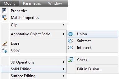
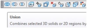
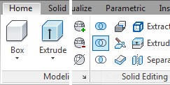
AutoCAD Command: UNION
The UNION command is used to join two or more solids together to form one solid object.
Shortcut: none
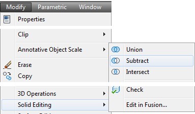
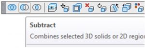
AutoCAD Command: SUBTRACT
The SUBTRACT command is used to subtract one or more solids from another solid.
Shortcut: SU
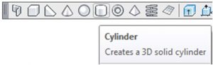
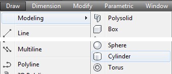
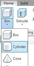
AutoCAD Command: CYLINDER
The CYLINDER command is used to create a solid cylinder primitive.
Shortcut: none
WORK ALONG: Creating Solid Models Using Boxes, Wedges and Cylinders
Step 1
Using the NEW command, start a new drawing using template: 3D Layout English.
Step 2
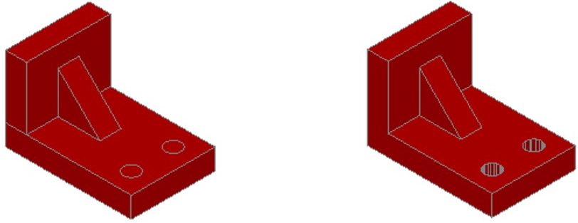
Save and name the drawing: AutoCAD 3D Workalong 17-1. (Figure Step 2A and 2B)
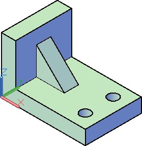
SE Isometric View – Solid Model
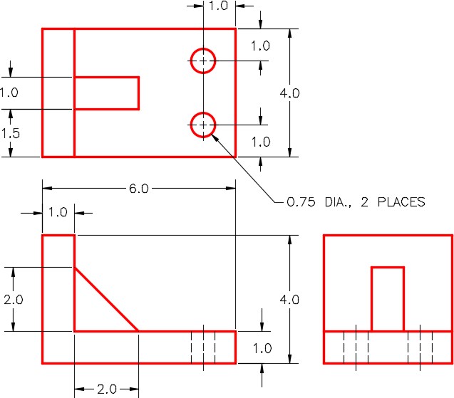
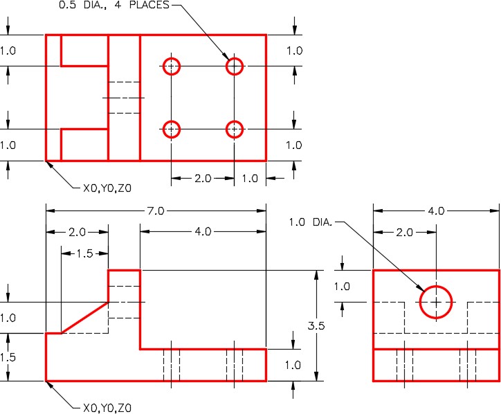
Dimensioned Multiview Drawing
Step 3
Set the current view to SE Isometric, the current UCS to World and the current visual style to 2D Wireframe.
Step 4
Set the current layer to Solid 7.
Step 5
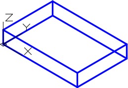
Enter the BOX command, as shown below, to draw the solid box. (Figure Step 5).
Command: BOX
Specify first corner or [Center]: 0,0,0 Specify other corner or [Cube/Length]: @6,4
(6 units in the positive X and 4 units in the positive Y.)
Specify height or [2Point] <3.1668>: 1
(1 unit in the positive Z.)
Command:
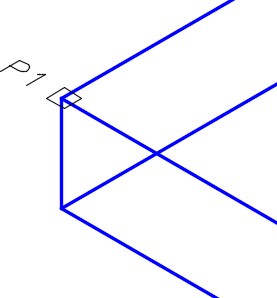
Step 6
Enter the BOX command, as shown below, to add a box to the model. (Figure Step 6A and 6B).
Command: BOX
Specify first corner or [Center]: (end) P1
Specify other corner or [Cube/Length]: @1,4
Specify height or [2Point] <1.0000>: 3
Command:
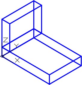
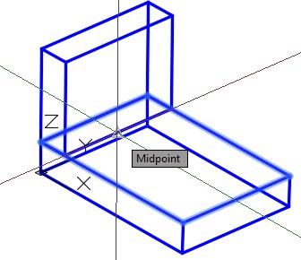
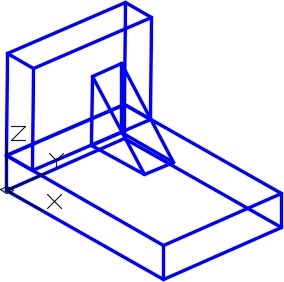
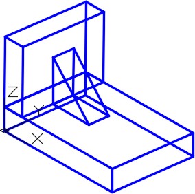
Step 7
Using on of the orbit commands, orbit the model slightly. Enter the WEDGE command, as shown below, to create a solid wedge primitive as shown in the figure. Using the MOVE command, move the wedge to centre it. Move the wedge by snapping to the midpoint of the wedge to the midpoint on the box. (Figure Step 7A, 7B, and 7C)
Command: WEDGE
Specify first corner or [Center]: (mid)
(See Figure Step 7A)
Specify other corner or [Cube/Length]: @2,1
Specify height or [2Point] <3.0000>: 2
Command:
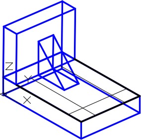
Step 8
Draw three construction lines on the edges of the box. (Figure Step 8)

Step 9
Offset the construction lines to locate the centre of the holes. (Figure Step 9)
Step 10
Enter the ISOLINES system variable, as shown below, setting it to 16. Command: ISOLINES
Enter new value for ISOLINES <4>: 16
Command:
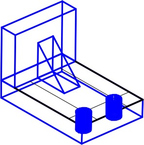
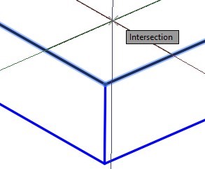
Step 11
Enter the CYLINDER command, as shown below, to construct a cylinder for the left hole. After you do that, construct the cylinder on the right side. (Figure Step 11A and 11B)
Command: CYLINDER
Current wire frame density: ISOLINES=16
Specify centre point for base of cylinder or [Elliptical] <0,0,0>: (int) P3
Specify radius for base of cylinder or [Diameter]: D
Specify diameter for base of cylinder: 0.75
Specify height of cylinder or [Center of other end]: -1
(Since the cylinder is constructed 1 unit in the -Z direction -1 is used here.)
Command:
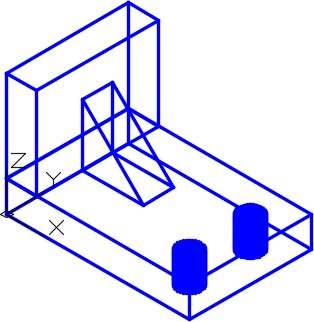
Step 12
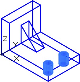
Turn layer Construction off and your model should appear as shown in the figure. (Figure Step 12)
Step 13
Enter the UNION command, as shown below, to create one solid from the two boxes and the wedge. (Figure Step 13)
Command: UNION
Select objects: 1 found
Select objects: 1 found, 2 total
Select objects: 1 found, 3 total
(Select one solid at a time by picking them.)
Select objects:
Command:
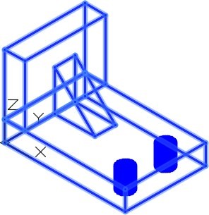
Step 14
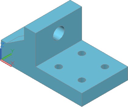
Your model is now one solid and should appear as shown in the figure. (Figure Step 14)
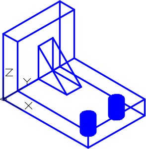
Step 15
Enter the SUBTRACT command, as shown below, to subtract the two cylinders from the model to create the holes. (Figure Step 15A and 15B)
Command: SUBTRACT
Select solids and regions to subtract from ..
Select objects: 1 found
(Select the solid model. See Figure Step 15A)
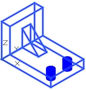
Select objects:
(Press Enter to change to subtract mode.)
Select solids and regions to subtract .. Select objects: 1 found
Select objects: 1 found, 2 total
(Select each cylinder by picking them one at a time See Figure Step 15B.)
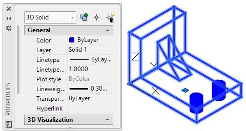
Step 16
Open the Properties window and select the solid model. Ensure it is one AutoCAD object only. (Figure Step 16)
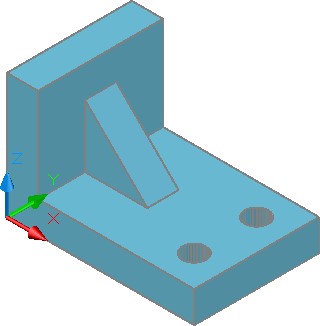
Step 17
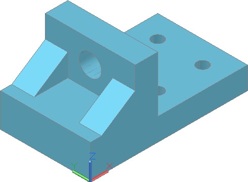
Set the current visual style to Realistic. (Figure Step 17)
Step 18
Save and close the drawing.
MUST KNOW: When two or more solid primitives are used to construct a solid model, the UNION and/or SUBTRACT commands must be used to create one solid object which is one AutoCAD object. When complete, a solid model must be only one object.
Key Principles
Key Principles in Module 17
- A solid model is the best possible computerized representation of an object. It is a much more complete model then a wireframe or a surfaced model. A solid model can be rendered or shaded plus the mass properties can be obtained from it.
- Using solid primitives is not the best method of solid modeling, but at times they can be a very useful modeling tool.
- Ensure that you disable osnap mode when you are not using When working in 3D, an enabled osnap mode can cause a lot of problems.
- The ISOLINES system variable is used set the number of contour lines that are used to construct curved surfaces in the solid model.
Lab Exercise 17-1
Time allowed: 40 minutes.
| Drawing Name | Template | Units |
|---|---|---|
| AutoCAD 3D Lab 17-1 | 3D Layout English | Inches |
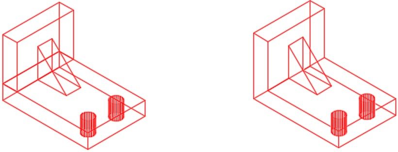
Step 1
On layer Solid 3, draw a solid model of the object. (Figure Step 1A, 1B, and 1C)
Dimensioned Multiview Drawing
Step 2
Set the Isolines to 16.
Step 3
Use the UNION and SUBTRACT commands to create one solid object only.
Step 4
Set the current visual style to Realistic and check the model by orbiting it with the with the 3DFORBIT command.
Step 5
Check to ensure that the solid is one object only. See Step 16 in WORKALONG: Creating Solid Models Using Boxes, Wedges and Cylinders.
Step 6
Save and close the drawing.
Lab Exercise 17-2
Time allowed: 40 minutes.
| Drawing Name | Template | Units |
|---|---|---|
| AutoCAD 3D Lab 17-2 | 3D Layout Metric | Millimeters |
Step 1
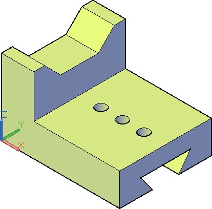
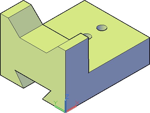
On layer Solid 1, draw a solid model of the object. (Figure Step 1A, 1B, and 1C)
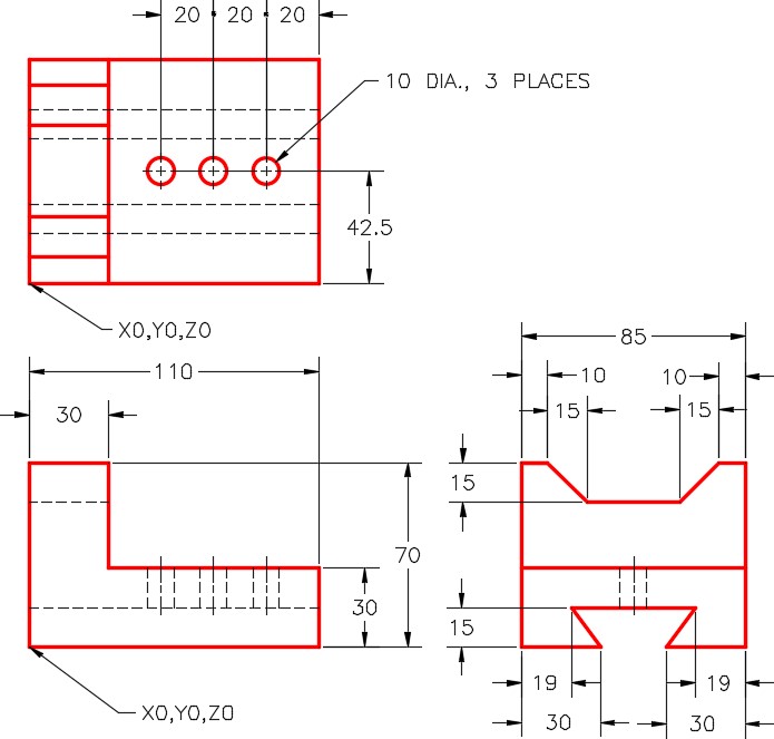
Dimensioned Multiview Drawing
Step 2
Set the Isolines to 20.
Step 3
If necessary, use the UNION and SUBTRACT commands to create one solid object only.
Step 4
Set the current visual style to Realistic and check the model by orbiting it with the with the 3DFORBIT command.
Step 5
Check to ensure that the solid is one object only. See Step 16 in WORKALONG: Creating Solid Models Using Boxes, Wedges and Cylinders.
Step 6
Save and close the drawing.