
4.2: Module 18 Solid Modeling – Part 2
- Page ID
- 19956

\( \newcommand{\vecs}[1]{\overset { \scriptstyle \rightharpoonup} {\mathbf{#1}} } \)
\( \newcommand{\vecd}[1]{\overset{-\!-\!\rightharpoonup}{\vphantom{a}\smash {#1}}} \)
\( \newcommand{\id}{\mathrm{id}}\) \( \newcommand{\Span}{\mathrm{span}}\)
( \newcommand{\kernel}{\mathrm{null}\,}\) \( \newcommand{\range}{\mathrm{range}\,}\)
\( \newcommand{\RealPart}{\mathrm{Re}}\) \( \newcommand{\ImaginaryPart}{\mathrm{Im}}\)
\( \newcommand{\Argument}{\mathrm{Arg}}\) \( \newcommand{\norm}[1]{\| #1 \|}\)
\( \newcommand{\inner}[2]{\langle #1, #2 \rangle}\)
\( \newcommand{\Span}{\mathrm{span}}\)
\( \newcommand{\id}{\mathrm{id}}\)
\( \newcommand{\Span}{\mathrm{span}}\)
\( \newcommand{\kernel}{\mathrm{null}\,}\)
\( \newcommand{\range}{\mathrm{range}\,}\)
\( \newcommand{\RealPart}{\mathrm{Re}}\)
\( \newcommand{\ImaginaryPart}{\mathrm{Im}}\)
\( \newcommand{\Argument}{\mathrm{Arg}}\)
\( \newcommand{\norm}[1]{\| #1 \|}\)
\( \newcommand{\inner}[2]{\langle #1, #2 \rangle}\)
\( \newcommand{\Span}{\mathrm{span}}\) \( \newcommand{\AA}{\unicode[.8,0]{x212B}}\)
\( \newcommand{\vectorA}[1]{\vec{#1}} % arrow\)
\( \newcommand{\vectorAt}[1]{\vec{\text{#1}}} % arrow\)
\( \newcommand{\vectorB}[1]{\overset { \scriptstyle \rightharpoonup} {\mathbf{#1}} } \)
\( \newcommand{\vectorC}[1]{\textbf{#1}} \)
\( \newcommand{\vectorD}[1]{\overrightarrow{#1}} \)
\( \newcommand{\vectorDt}[1]{\overrightarrow{\text{#1}}} \)
\( \newcommand{\vectE}[1]{\overset{-\!-\!\rightharpoonup}{\vphantom{a}\smash{\mathbf {#1}}}} \)
\( \newcommand{\vecs}[1]{\overset { \scriptstyle \rightharpoonup} {\mathbf{#1}} } \)
\( \newcommand{\vecd}[1]{\overset{-\!-\!\rightharpoonup}{\vphantom{a}\smash {#1}}} \)
\(\newcommand{\avec}{\mathbf a}\) \(\newcommand{\bvec}{\mathbf b}\) \(\newcommand{\cvec}{\mathbf c}\) \(\newcommand{\dvec}{\mathbf d}\) \(\newcommand{\dtil}{\widetilde{\mathbf d}}\) \(\newcommand{\evec}{\mathbf e}\) \(\newcommand{\fvec}{\mathbf f}\) \(\newcommand{\nvec}{\mathbf n}\) \(\newcommand{\pvec}{\mathbf p}\) \(\newcommand{\qvec}{\mathbf q}\) \(\newcommand{\svec}{\mathbf s}\) \(\newcommand{\tvec}{\mathbf t}\) \(\newcommand{\uvec}{\mathbf u}\) \(\newcommand{\vvec}{\mathbf v}\) \(\newcommand{\wvec}{\mathbf w}\) \(\newcommand{\xvec}{\mathbf x}\) \(\newcommand{\yvec}{\mathbf y}\) \(\newcommand{\zvec}{\mathbf z}\) \(\newcommand{\rvec}{\mathbf r}\) \(\newcommand{\mvec}{\mathbf m}\) \(\newcommand{\zerovec}{\mathbf 0}\) \(\newcommand{\onevec}{\mathbf 1}\) \(\newcommand{\real}{\mathbb R}\) \(\newcommand{\twovec}[2]{\left[\begin{array}{r}#1 \\ #2 \end{array}\right]}\) \(\newcommand{\ctwovec}[2]{\left[\begin{array}{c}#1 \\ #2 \end{array}\right]}\) \(\newcommand{\threevec}[3]{\left[\begin{array}{r}#1 \\ #2 \\ #3 \end{array}\right]}\) \(\newcommand{\cthreevec}[3]{\left[\begin{array}{c}#1 \\ #2 \\ #3 \end{array}\right]}\) \(\newcommand{\fourvec}[4]{\left[\begin{array}{r}#1 \\ #2 \\ #3 \\ #4 \end{array}\right]}\) \(\newcommand{\cfourvec}[4]{\left[\begin{array}{c}#1 \\ #2 \\ #3 \\ #4 \end{array}\right]}\) \(\newcommand{\fivevec}[5]{\left[\begin{array}{r}#1 \\ #2 \\ #3 \\ #4 \\ #5 \\ \end{array}\right]}\) \(\newcommand{\cfivevec}[5]{\left[\begin{array}{c}#1 \\ #2 \\ #3 \\ #4 \\ #5 \\ \end{array}\right]}\) \(\newcommand{\mattwo}[4]{\left[\begin{array}{rr}#1 \amp #2 \\ #3 \amp #4 \\ \end{array}\right]}\) \(\newcommand{\laspan}[1]{\text{Span}\{#1\}}\) \(\newcommand{\bcal}{\cal B}\) \(\newcommand{\ccal}{\cal C}\) \(\newcommand{\scal}{\cal S}\) \(\newcommand{\wcal}{\cal W}\) \(\newcommand{\ecal}{\cal E}\) \(\newcommand{\coords}[2]{\left\{#1\right\}_{#2}}\) \(\newcommand{\gray}[1]{\color{gray}{#1}}\) \(\newcommand{\lgray}[1]{\color{lightgray}{#1}}\) \(\newcommand{\rank}{\operatorname{rank}}\) \(\newcommand{\row}{\text{Row}}\) \(\newcommand{\col}{\text{Col}}\) \(\renewcommand{\row}{\text{Row}}\) \(\newcommand{\nul}{\text{Nul}}\) \(\newcommand{\var}{\text{Var}}\) \(\newcommand{\corr}{\text{corr}}\) \(\newcommand{\len}[1]{\left|#1\right|}\) \(\newcommand{\bbar}{\overline{\bvec}}\) \(\newcommand{\bhat}{\widehat{\bvec}}\) \(\newcommand{\bperp}{\bvec^\perp}\) \(\newcommand{\xhat}{\widehat{\xvec}}\) \(\newcommand{\vhat}{\widehat{\vvec}}\) \(\newcommand{\uhat}{\widehat{\uvec}}\) \(\newcommand{\what}{\widehat{\wvec}}\) \(\newcommand{\Sighat}{\widehat{\Sigma}}\) \(\newcommand{\lt}{<}\) \(\newcommand{\gt}{>}\) \(\newcommand{\amp}{&}\) \(\definecolor{fillinmathshade}{gray}{0.9}\)Module 18 Solid Modeling – Part 2
Learning Outcomes
When you have completed this module, you will be able to:
- Describe how solid models are created by extrusion or revolving.
- Apply the JOIN command to create a single 2D or 3D object from existing objects.
- Apply the EXTRUDE, PRESSPULL, and REVOLVE commands to draw solid models.
- Set the DELOBJ system variable to control objects used to create solid models.
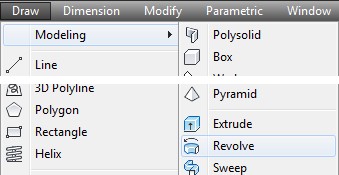
Constructing Solid Models Without Using Solid Primitives
Constructing most solid models using solid primitives would be to difficult and slow. It is much faster and simpler to construct most solid models using the EXTRUDE and/or the REVOLVE commands.
Extruding
Extruding involves drawing a closed object and, using the EXTRUDE or the PUSHPULL command, project it in the Z direction at a given distance. See Figure 18-1. The closed object can be a 2D polygon, a circle or an ellipse. Extruded solids can then be joined with the UNION command or subtracted using the SUBTRACT command to form the final solid model.
Revolving
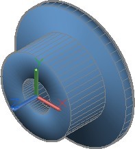
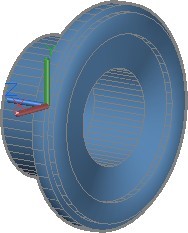
Not all solid models can be extruded. A solid model that is symmetrical can be created by revolving a closed object. See Figure 18-2. The closed 2D object can be a polygon, a circle or an ellipse. It is then revolved around an axis. The contour of the object will create the solid as it is revolved around the axis. It can be revolved any angle from 1 degree to 360 degrees.
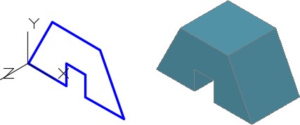
Extruding a Solid Model
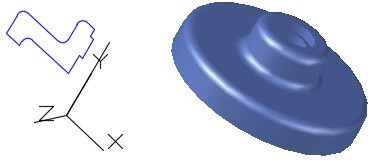
Revolving a Solid Model
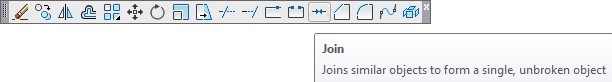
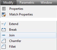
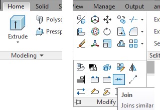
AutoCAD Command: JOIN
The JOIN combines a series of finite linear and open curved objects at their common endpoints to create a single 2D or 3D object.
Shortcut: J
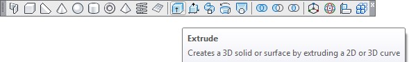
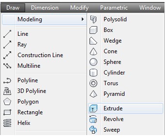
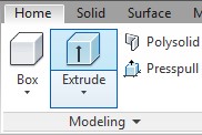
AutoCAD Command: EXTRUDE
The EXTRUDE command is used to create a solid by projecting a closed 2D object along the Z axis of the current UCS.
Shortcut: EXT
AutoCAD Command: DELOBJ
The DELOBJ system variable controls whether the EXTRUDE or REVOLVE command deletes or retains the closed object when the command is executed.
Command: DELOBJ
Enter new value for DELOBJ <0>: Command:
Set to:
0 – Will retain the closed polygon
1 – Will delete the closed polygon
WORK ALONG: Creating a Extruded Solid Model Using the EXTRUDE Command
Step 1
Using the NEW command, start a new drawing using template: 3D Layout English.
Step 2
Save and name the drawing: AutoCAD 3D Workalong 18-1.
Step 3
Set the current visual style to 2D Wireframe, set the layer: Pline as the current layer, the current view to SE Isometric, and the current UCS to World.
Step 4
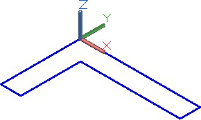
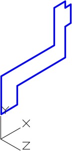
Draw the top contour of the wireframe model only. Use the multiview drawing as a reference. (Figure Step 4A and 4B)
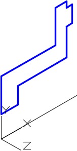
Step 5
Set the current UCS to Top and locate it at the centre of the circle as shown in the figure. (Figure Step 5)
Step 6
Enter the DELOBJ system variable as shown below. Ensure that it is set to 0. Command: DELOBJ
Enter new value for DELOBJ <1>: 0
Command:
Step 7
Set the system variable ISOLINES to 32, as shown below. Command: ISOLINES
Enter new value for ISOLINES <4>: 32
Command:
Step 8
Enter the JOIN command, as shown below, to create a single 2D polyline from the 8 lines and arcs. (Figure Step 8)
Command: JOIN
Select source object or multiple objects to join at once:
1 found
Select objects to join: 1 found, 2 total
Select objects to join: 1 found, 3 total
Select objects to join: 1 found, 4 total
Select objects to join: 1 found, 5 total
Select objects to join: 1 found, 6 total
Select objects to join: 1 found, 7 total
Select objects to join: 1 found, 8 total
Select objects to join:
8 objects converted to 1 polyline
Command:
Step 9
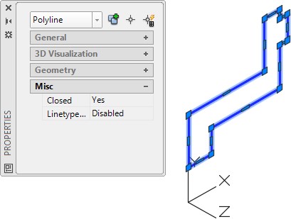
Click the newly created pline and insure it is closed using the Properties window. (Figure Step 9)
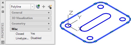
Step 10
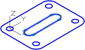
Using what you learned in the last two steps join the inside 4 lines and arcs to create on 2D polyline. Check to ensure it is closed using the Properties window. (Figure Step 10)
Step 11
Set layer: Solid 3 as the current layer. Enter the EXTRUDE command, as shown below, to create the solid model.
Command: EXTRUDE
Current wire frame density: ISOLINES=32
Select objects: 6 found
(Select all of the objects in a window or pick then individually.)
Select objects:
Specify height of extrusion or [Path]: -0.75
(Use -0.75 since the extrusion in the negative Z direction.)
Specify angle of taper for extrusion <0>:
(Press Enter to select the default.)
Command:
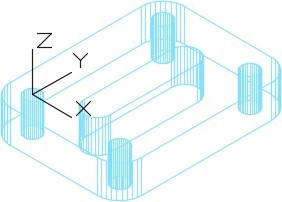
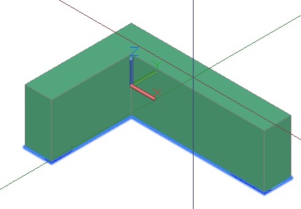
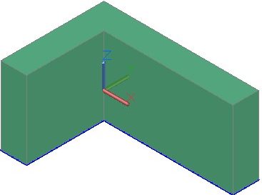
Step 12
Turn layer: Pline off and your model should appear as shown in the figure. (Figure Step 12)
Step 13
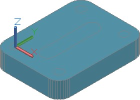
Set the current visual style to Realistic. (Figure Step 13)
Step 14
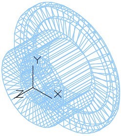
Set the current visual style to 2D Wireframe. Enter the SUBTRACT command to subtract the five inner solids from the larger solid. (Figure Step 14)
Step 15
Set the current visual style to Realistic. Your model should now appear as shown in the figures. Using the ORBIT command, orbit the model to enure the holes go through the model. (Figure Step 15)
Step 16
Save and close the drawing.
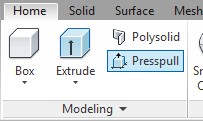
AutoCAD Command: PRESSPULL
The PRESSPULL command is used to create a solid by either selecting an area formed by a closed boundary (or boundaries) or a closed 2D object.
Shortcut: none
WORK ALONG: Creating a Extruded Solid Model Using the PRESSPULL Command
Step 1
Using the NEW command, start a new drawing using template: 3D Layout Metric.
Step 2
Save and name the drawing: AutoCAD 3D Workalong 18-2.
Step 3
Set the current visual style to 3D Wireframe, set layer: Pline, the current view to SE Isometric, and the current UCS to World.
Step 4
Draw the top contour of the wireframe model only. Use the multiview drawing as a reference. (Figure Step 4A and 4B)
Step 5
Use the JOIN command to create a single 2D polyline. Use the Properties window to ensure that the polyline is closed.
Step 6
Set layer: Solid 2 as the current layer.
Step 7
Enter the DELOBJ system variable as shown below and ensure that it is set to 0.
Command: DELOBJ
Enter new value for DELOBJ <1>: 0
Command:
Step 8
Enter the PRESSPULL command. When prompted, select the polyline. Move the cursor in the positive Z direction and the solid will extrude with it. Enter 30 for the height. (Figure Step 8A and 8B)
Command: PRESSPULL
Select object or bounded area:
Specify extrusion height or [Multiple]:
Specify extrusion height or [Multiple]: 30
1 extrusion(s) created
Select object or bounded area:
Command:
Step 9
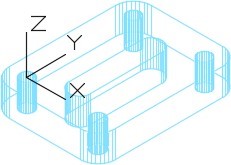
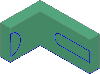
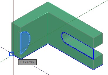
Using the multiview drawing for the dimensions, draw the lines and arcs in the Front and Right Side of the model. Use the JOIN command to join the plines and ensure that they are closed. (Figure Step 9)
Step 10
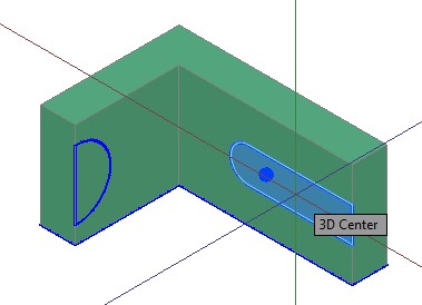
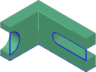
Enter the PRESSPULL command and when prompted, select inside the closed pline as shown in the figure. Snap to the back corner to indicate the depth of the extrusion. (Figure Step 10A and 10B)
Step 11
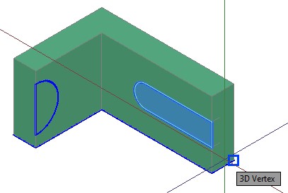
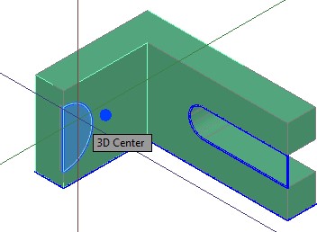
Using the same principle as Step 10, use the PRESSPULL command to extrude the other pline. (Figure Step 11A, 11B, and 11C)
Step 12
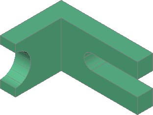
Turn layer: Pline off.
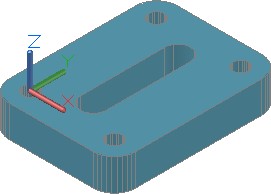
Step 13
Your completed model should appear as shown on the figure. (Figure Step 13)
Step 14
Save and close the drawing
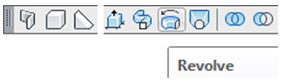
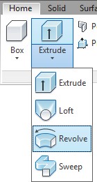
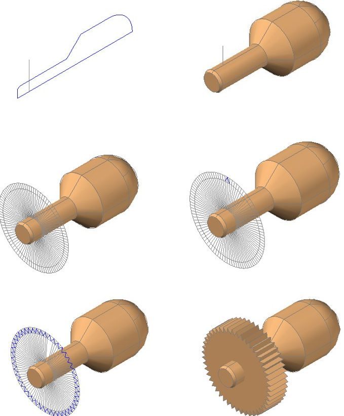
AutoCAD Command: REVOLVE
The REVOLVE command is used to create a solid model by revolving a 2D object around an axis.
Shortcut: REV
WORK ALONG: Creating a Revolved Solid Model
Step 1
Using the NEW command, start a new drawing using template: 3D Layout English.
Step 2
Save and name the drawing: AutoCAD 3D Workalong 18-3. (Figure Step 2)
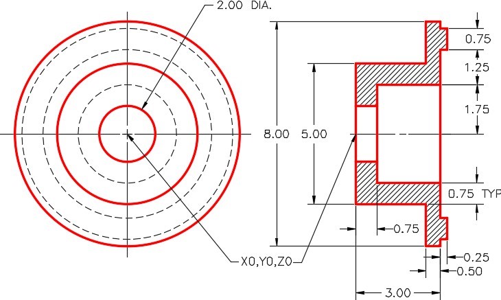
Dimensioned Multiview Drawing
Step 3
Set layer Pline as the current layer and current visual style to 2D Wireframe.
Step 4
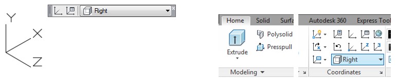
Set the current view to SE Isometric and the current UCS to Right. (Figure Step 4)
Step 5
Using the multiview drawing as a reference, draw one-half of the right side cross section of the solid part of the object. (Figure Step 5)
Step 6
On layer: Construction, from 0,0,0 draw a line, of any length, along the X axis. Use ortho mode to draw it quicker. This will be the axis for the revolution and is the centre line of the solid. (Figure Step 6)
Step 7
Using the JOIN command, create a closed polygon from the lines. Ensure that it is closed. (Figure Step 7)
Step 8
Set the ISOLINES system variable to 48 as shown below. Command: ISOLINES
Enter new value for ISOLINES <4>: 48
Command:
Step 9
Set layer Solid 3 as the current layer. Enter the REVOLVE command, as shown below. After completing the command, the model should appear as shown in the figure. (Figure Step 9)
Command: REVOLVE
Current wire frame density: ISOLINES=48
Select objects: 1 found
(Select the closed polyline.)
Select objects:
(Press Enter.)
Specify start point for axis of revolution or define axis by
[Object/X (axis)/Y (axis)]: O
Select an object:
(Select the axis (the construction line.)
Specify angle of revolution <360>:
(Press Enter to select the default.)
Command:
Step 10
Turn off layers: Construction and Pline and set the current visual style to Realistic. (Figure Step 10)
SE Isometric View
Step 11
Using 3D Orbit, orbit the model as shown in the figure. (Figure Step 11).
Step 12
Save and close the drawing.
Key Principles
Key Principles in Module 18
- The object being extruded or revolved with the EXTRUDE, PRESSPULL, and REVOLVE commands must be closed polyline, a circle, or an ellipse.
- Before entering the EXTRUDE command, ensure that UCS is located with the Z axis going in the direction of the extrusion.
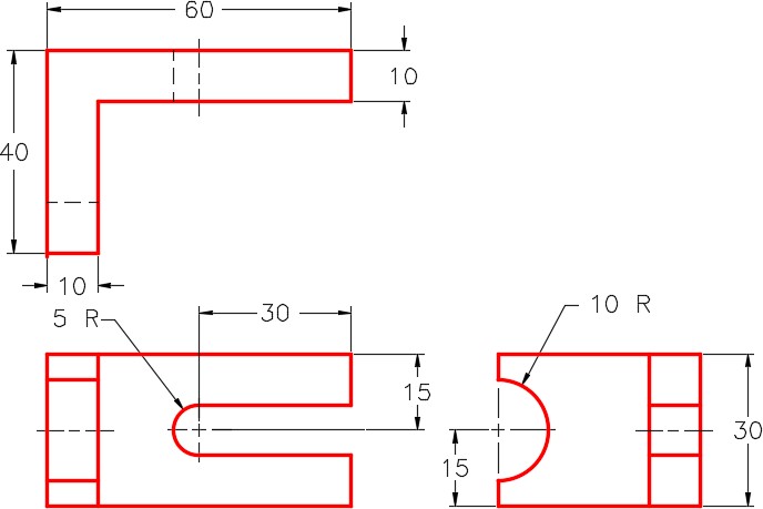
Lab Exercise 18-1
Time allowed: 45 minutes.
| Drawing Name | Template | Units |
|---|---|---|
| AutoCAD 3D Lab 18-1 | 3D Layout Metric | Millimeters |
Step 1
Set the system variable DELOBJ to 0.
Step 2
Draw the closed plines on layer: Pline.
Step 3
On layer: Solid 1, draw a solid model of the object. (Figure Step 3A and 3B)
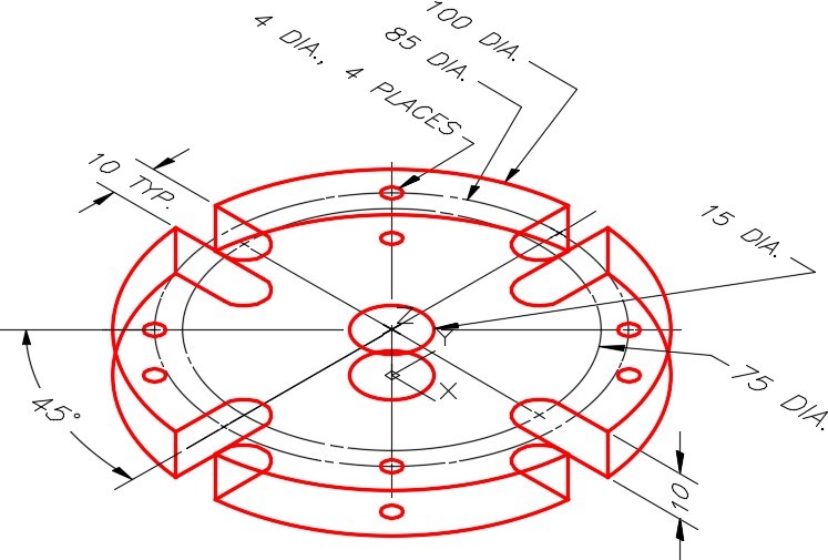
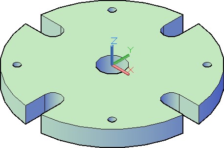
Solid Model SE Isometric View
Step 4
Use the UNION and SUBTRACT commands to complete the solid model. When complete, the solid must be one object.
Step 5
Turn layers: Construction and Pline off and set the current visual style to Realistic.
Step 6
Set the Insertion Units, change the current UCS to World and check the model with the key.
Step 7
Save and close the drawing.
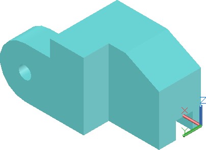
Lab Exercise 18-2
Time allowed: 45 minutes.
| Drawing Name | Template | Units |
|---|---|---|
| AutoCAD 3D Lab 18-2 | 3D Layout Metric | Millimeters |
Step 1
Set the system variable DELOBJ to 0.
Step 2
On layer: Solid 3, draw a solid model of the object. (Figure Step 2A, 2B, 2C, and 2D)
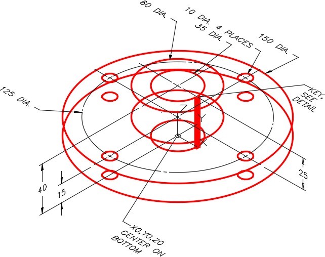
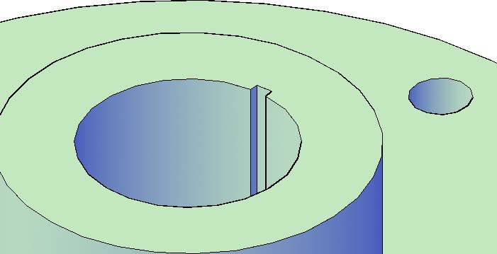
View of Keyway – Rotated
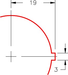
Key Detail
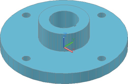
Solid Model SE Isometric View
Step 3
On layer: Pline, draw the closed plines.
Step 4
Use the UNION and SUBTRACT commands to complete the solid model. When complete, the solid must be one object.
Step 5
Turn layers: Construction and Pline off and set the current visual style to Realistic.
Step 6
Set the Insertion Units, change the current UCS to World, and check the model with the key.
Step 7
Save and close the drawing.
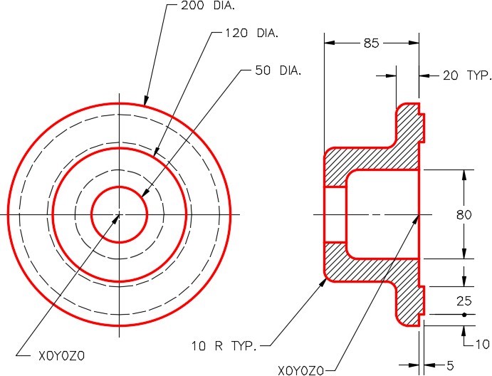
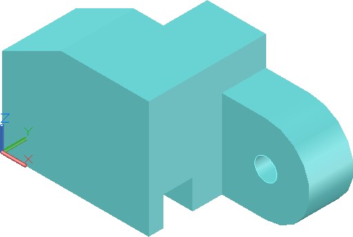
Lab Exercise 18-3
Time allowed: 60 minutes.
| Drawing Name | Template | Units |
|---|---|---|
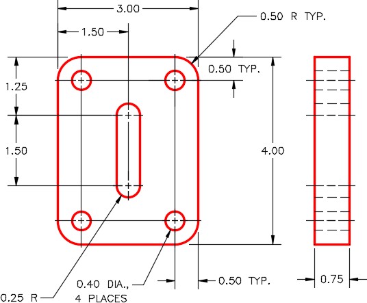
| AutoCAD 3D Lab 18-3 | 3D Layout English | Inches |
Step 1
Set the system variable DELOBJ to 0.
Step 2
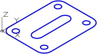
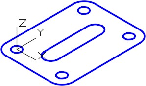
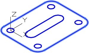
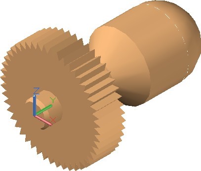
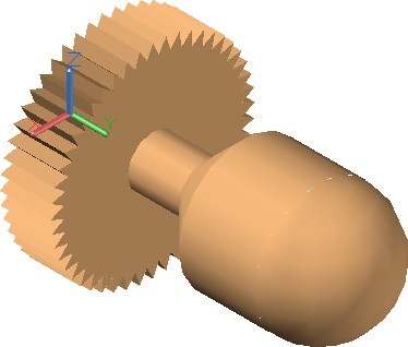
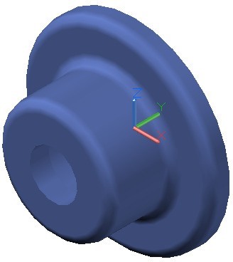
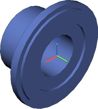
On layer: Solid 4, draw a solid model of the object. (Figure Step 2A, 2B, and 2C)
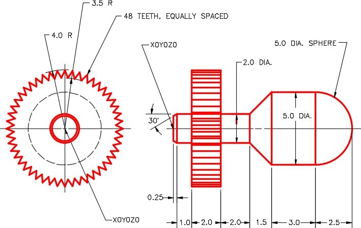
Dimensioned Multiview Drawing
Step 3
On layer: Pline, draw the closed plines.
Step 4
Use the UNION command to complete the solid model. When complete, the solid must be one object.
Step 5
Turn layers: Construction and Pline off and set the current visual style to Realistic.
Step 6
Set the Insertion Units, change the current UCS to World, and check the model with the key.
Step 7
Save and close the drawing.
Hint 1
See steps below:
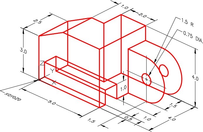
Lab Exercise 18-4
Time allowed: 45 minutes.
| Drawing Name | Template | Units |
|---|---|---|
| AutoCAD 3D Lab 18-4 | 3D Layout Metric | Millimeters |
Step 1
Set the system variable DELOBJ to 0.
Step 2
On layer: Solid 5, draw a solid model of the object. (Figure Step 2A, 2B, and 2C)
Dimensioned Multiview Drawing
Step 3
On layer: Pline, draw the closed pline.
Step 4
When complete, the solid model must be one object.
Step 5
Turn layers: Construction and Pline off and set the current visual style to Realistic.
Step 6
Set the Insertion Units, change the current UCS to World, and check the model with the key.
Step 7
Save and close the drawing.
Lab Exercise 18-5
Time allowed: 45 minutes.
| Drawing Name | Template | Units |
|---|---|---|
| AutoCAD 3D Lab 18-5 | 3D Layout English | Inches |
Step 1
Set the system variable DELOBJ to 0.
Step 2
On layer: Solid 3, draw a solid model of the object. (Figure Step 2A, 2B, and 2C)
Dimensioned Wireframe Model
Completed Solid Model SE Isometric View
Completed Solid Model NW Isometric View
Step 3
On layer: Pline, draw the closed plines.
Step 4
Use the UNION and SUBTRACT commands to complete the solid model. When complete, the solid must be one object.
Step 5
Turn layers: Construction and Pline off and set the current visual style to Realistic.
Step 6
Set the Insertion Units, change the current UCS to World, and check the model with the key.
Step 7
Save and close the drawing.