
4.3: Module 19 Solid Modeling – Part 3
- Page ID
- 19963

\( \newcommand{\vecs}[1]{\overset { \scriptstyle \rightharpoonup} {\mathbf{#1}} } \)
\( \newcommand{\vecd}[1]{\overset{-\!-\!\rightharpoonup}{\vphantom{a}\smash {#1}}} \)
\( \newcommand{\id}{\mathrm{id}}\) \( \newcommand{\Span}{\mathrm{span}}\)
( \newcommand{\kernel}{\mathrm{null}\,}\) \( \newcommand{\range}{\mathrm{range}\,}\)
\( \newcommand{\RealPart}{\mathrm{Re}}\) \( \newcommand{\ImaginaryPart}{\mathrm{Im}}\)
\( \newcommand{\Argument}{\mathrm{Arg}}\) \( \newcommand{\norm}[1]{\| #1 \|}\)
\( \newcommand{\inner}[2]{\langle #1, #2 \rangle}\)
\( \newcommand{\Span}{\mathrm{span}}\)
\( \newcommand{\id}{\mathrm{id}}\)
\( \newcommand{\Span}{\mathrm{span}}\)
\( \newcommand{\kernel}{\mathrm{null}\,}\)
\( \newcommand{\range}{\mathrm{range}\,}\)
\( \newcommand{\RealPart}{\mathrm{Re}}\)
\( \newcommand{\ImaginaryPart}{\mathrm{Im}}\)
\( \newcommand{\Argument}{\mathrm{Arg}}\)
\( \newcommand{\norm}[1]{\| #1 \|}\)
\( \newcommand{\inner}[2]{\langle #1, #2 \rangle}\)
\( \newcommand{\Span}{\mathrm{span}}\) \( \newcommand{\AA}{\unicode[.8,0]{x212B}}\)
\( \newcommand{\vectorA}[1]{\vec{#1}} % arrow\)
\( \newcommand{\vectorAt}[1]{\vec{\text{#1}}} % arrow\)
\( \newcommand{\vectorB}[1]{\overset { \scriptstyle \rightharpoonup} {\mathbf{#1}} } \)
\( \newcommand{\vectorC}[1]{\textbf{#1}} \)
\( \newcommand{\vectorD}[1]{\overrightarrow{#1}} \)
\( \newcommand{\vectorDt}[1]{\overrightarrow{\text{#1}}} \)
\( \newcommand{\vectE}[1]{\overset{-\!-\!\rightharpoonup}{\vphantom{a}\smash{\mathbf {#1}}}} \)
\( \newcommand{\vecs}[1]{\overset { \scriptstyle \rightharpoonup} {\mathbf{#1}} } \)
\( \newcommand{\vecd}[1]{\overset{-\!-\!\rightharpoonup}{\vphantom{a}\smash {#1}}} \)
\(\newcommand{\avec}{\mathbf a}\) \(\newcommand{\bvec}{\mathbf b}\) \(\newcommand{\cvec}{\mathbf c}\) \(\newcommand{\dvec}{\mathbf d}\) \(\newcommand{\dtil}{\widetilde{\mathbf d}}\) \(\newcommand{\evec}{\mathbf e}\) \(\newcommand{\fvec}{\mathbf f}\) \(\newcommand{\nvec}{\mathbf n}\) \(\newcommand{\pvec}{\mathbf p}\) \(\newcommand{\qvec}{\mathbf q}\) \(\newcommand{\svec}{\mathbf s}\) \(\newcommand{\tvec}{\mathbf t}\) \(\newcommand{\uvec}{\mathbf u}\) \(\newcommand{\vvec}{\mathbf v}\) \(\newcommand{\wvec}{\mathbf w}\) \(\newcommand{\xvec}{\mathbf x}\) \(\newcommand{\yvec}{\mathbf y}\) \(\newcommand{\zvec}{\mathbf z}\) \(\newcommand{\rvec}{\mathbf r}\) \(\newcommand{\mvec}{\mathbf m}\) \(\newcommand{\zerovec}{\mathbf 0}\) \(\newcommand{\onevec}{\mathbf 1}\) \(\newcommand{\real}{\mathbb R}\) \(\newcommand{\twovec}[2]{\left[\begin{array}{r}#1 \\ #2 \end{array}\right]}\) \(\newcommand{\ctwovec}[2]{\left[\begin{array}{c}#1 \\ #2 \end{array}\right]}\) \(\newcommand{\threevec}[3]{\left[\begin{array}{r}#1 \\ #2 \\ #3 \end{array}\right]}\) \(\newcommand{\cthreevec}[3]{\left[\begin{array}{c}#1 \\ #2 \\ #3 \end{array}\right]}\) \(\newcommand{\fourvec}[4]{\left[\begin{array}{r}#1 \\ #2 \\ #3 \\ #4 \end{array}\right]}\) \(\newcommand{\cfourvec}[4]{\left[\begin{array}{c}#1 \\ #2 \\ #3 \\ #4 \end{array}\right]}\) \(\newcommand{\fivevec}[5]{\left[\begin{array}{r}#1 \\ #2 \\ #3 \\ #4 \\ #5 \\ \end{array}\right]}\) \(\newcommand{\cfivevec}[5]{\left[\begin{array}{c}#1 \\ #2 \\ #3 \\ #4 \\ #5 \\ \end{array}\right]}\) \(\newcommand{\mattwo}[4]{\left[\begin{array}{rr}#1 \amp #2 \\ #3 \amp #4 \\ \end{array}\right]}\) \(\newcommand{\laspan}[1]{\text{Span}\{#1\}}\) \(\newcommand{\bcal}{\cal B}\) \(\newcommand{\ccal}{\cal C}\) \(\newcommand{\scal}{\cal S}\) \(\newcommand{\wcal}{\cal W}\) \(\newcommand{\ecal}{\cal E}\) \(\newcommand{\coords}[2]{\left\{#1\right\}_{#2}}\) \(\newcommand{\gray}[1]{\color{gray}{#1}}\) \(\newcommand{\lgray}[1]{\color{lightgray}{#1}}\) \(\newcommand{\rank}{\operatorname{rank}}\) \(\newcommand{\row}{\text{Row}}\) \(\newcommand{\col}{\text{Col}}\) \(\renewcommand{\row}{\text{Row}}\) \(\newcommand{\nul}{\text{Nul}}\) \(\newcommand{\var}{\text{Var}}\) \(\newcommand{\corr}{\text{corr}}\) \(\newcommand{\len}[1]{\left|#1\right|}\) \(\newcommand{\bbar}{\overline{\bvec}}\) \(\newcommand{\bhat}{\widehat{\bvec}}\) \(\newcommand{\bperp}{\bvec^\perp}\) \(\newcommand{\xhat}{\widehat{\xvec}}\) \(\newcommand{\vhat}{\widehat{\vvec}}\) \(\newcommand{\uhat}{\widehat{\uvec}}\) \(\newcommand{\what}{\widehat{\wvec}}\) \(\newcommand{\Sighat}{\widehat{\Sigma}}\) \(\newcommand{\lt}{<}\) \(\newcommand{\gt}{>}\) \(\newcommand{\amp}{&}\) \(\definecolor{fillinmathshade}{gray}{0.9}\)Module 19 Solid Modeling – Part 3
Learning Outcomes
When you have completed this module, you will be able to:
- Describe how the UNION, SUBTRACT, and INTERSECT commands are used and applied when solid modeling.
- Apply the INTERSECT, FILLETEDGE, CHAMFEREDGE, and OFFSETEDGE commands to construct and modify solid models.
Working With Composite Solids
When you are constructing solid models, it is important to ensure that the completed solid model consists of only one object. The three commands used to help you to do this are UNION, SUBTRACT and INTERSECT. Study the following figures to help you understand how these commands affect the solid model.
Figure 19-1 shows two solid models in which parts of each one occupies the same 3D space. This, of course, would be impossible in real life.
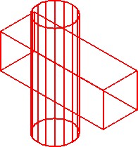
Two Solids
Figure 19-2 shows the same model after the UNION command was used to join the two solids into one.
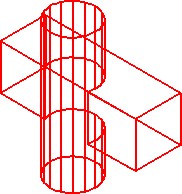
One Solid
Figure 19-3 shows a shaded model and how the model in Figure 19-1 will appear when the two solids are joined together with the UNION command.
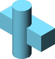
One Solid – Joined With UNION Command
Figure 19-4 shows how the two solids in Figure 19-1 will appear when the cylinder is subtracted from the box using the SUBTRACT command.
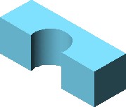
One Solid – Subtracted
Figure 19-5 shows how the two models in Figure 19-1 would appear when the box is subtracted from the cylinder using the SUBTRACT command.

One Solid
Subtracted
Figure 19-6 shows how the solid models in Figure 19-1 would appear if the INTERSECT command is used. Notice how only the volume shared by the two models remains.

One Solid
Intersection
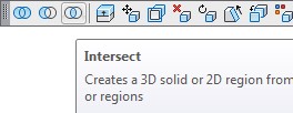
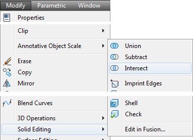
AutoCAD Command: INTERSECT
The INTERSECT command is used to create a solid by finding the volume shared by two or more solids.
Shortcut: none
WORK ALONG: Creating a Solid Model by Intersecting Two or Three Solid Models
Step 1
Using the NEW command, start a new drawing using template: 3D Layout English.
Step 2
Save and name the drawing: AutoCAD 3D Workalong 19-1.
Step 3
Ensure that the DELOBJ system variable is set to 0.
Step 4
Set layer: Pline as the current layer, the current UCS to Front, the current view to SE Isometric, and the current visual style to 2D Wireframe.
Step 5
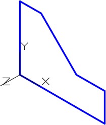
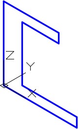
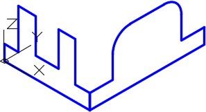
Set the current UCS to Front. Using the figures as a reference, draw the contour of the Front view. (Figure Step 5A and 5B)
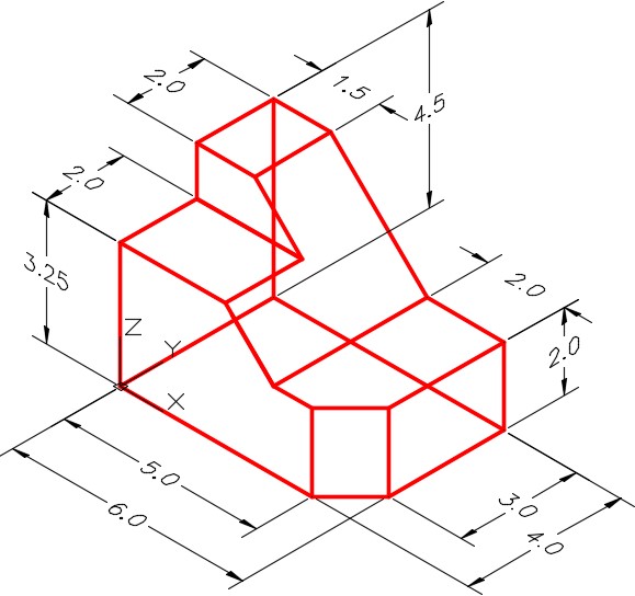
Dimensioned Wireframe Model
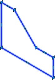
Step 6
Using the JOIN command, create a closed polyline. (Figure Step 6)
Step 7
Set the current UCS to Right and relocate the UCS to the right side as shown in the figure. Using the PLINE command, draw a closed pline of the contour of the right side. (Figure Step 7)
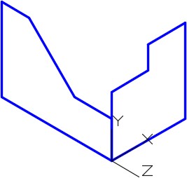
Step 8
Set the current UCS to Top and relocate it to the top corner of the model as shown in the figure. Using the PLINE command, draw a closed pline of the contour of the top view. (Figure Step 8)
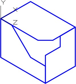
Step 9
Set layer: Solid 3 as the current layer. Extrude the Front view the depth of the model. (Figure Step 9)
Step 10
Set the current visual style to Realistic to see the extruded solid. (Figure Step 10)
Step 11
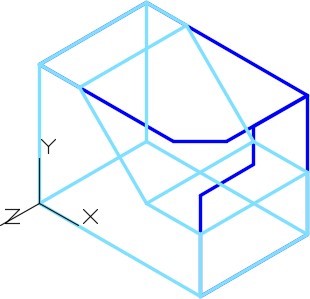
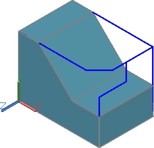
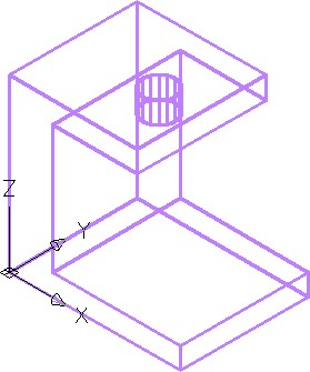
Set the current visual style to 2D Wireframe. Using PRESSPULL, extrude the Right Side and the Top view. Set the current visual style to Realistic to see all three extruded solids at the same time. (Figure Step 11A and 11B)
Step 12
Save drawing.
Step 13
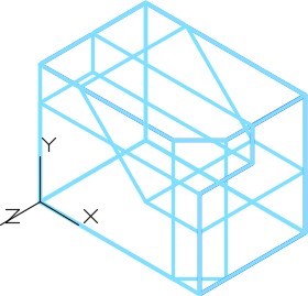
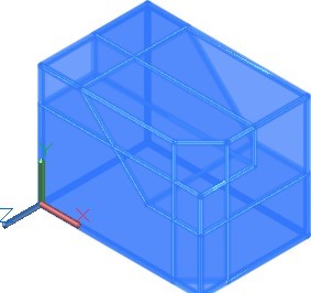
Set the current visual style to 2D Wireframe. Enter the INTERSECT command, as shown below, to create the common solid from the three intersecting solids. (Figure Step 13)
Command: INTERSECT
Select objects: 1 found
Select objects: 1 found, 2 total
Select objects: 1 found, 3 total
(Select each of the solid models.)
Select objects:
Command:
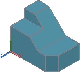
Step 14
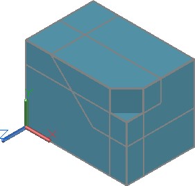
Set the current visual style to Realistic. (Figure Step 14)
Step 15
Save and close the drawing.
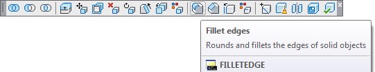
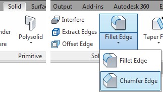
AutoCAD Command: FILLETEDGE
The FILLETEDGE command is used to create a fillet (tangent arc) on the edge or edges of a solid model.
Shortcut: none
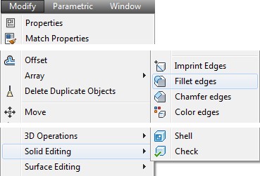
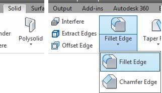
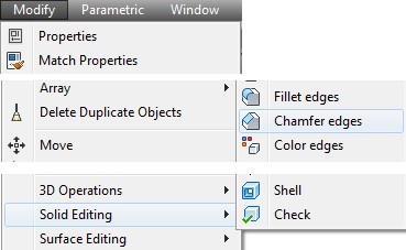
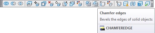
AutoCAD Command: CHAMFEREDGE
The CHAMFEREDGE command is used to create a chamfer on the edge or edges of a solid model.
Shortcut: none
WORK ALONG: Creating Fillets and Chamfers on Solid Models
Step 1
Using the NEW command, start a new drawing using template: 3D Layout English.
Step 2
Save and name the drawing: AutoCAD 3D Workalong 19-2.
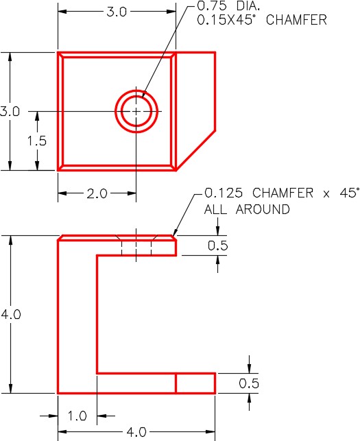
Step 3
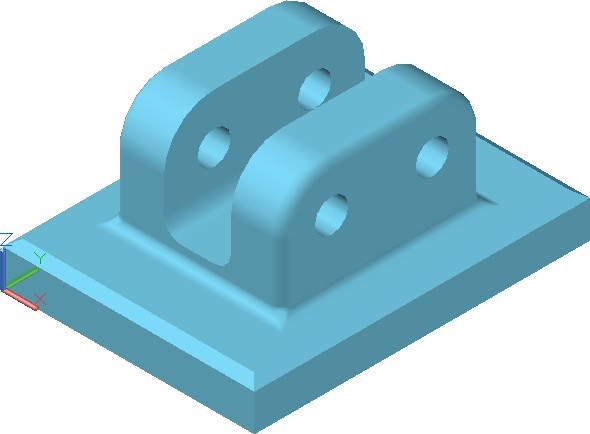
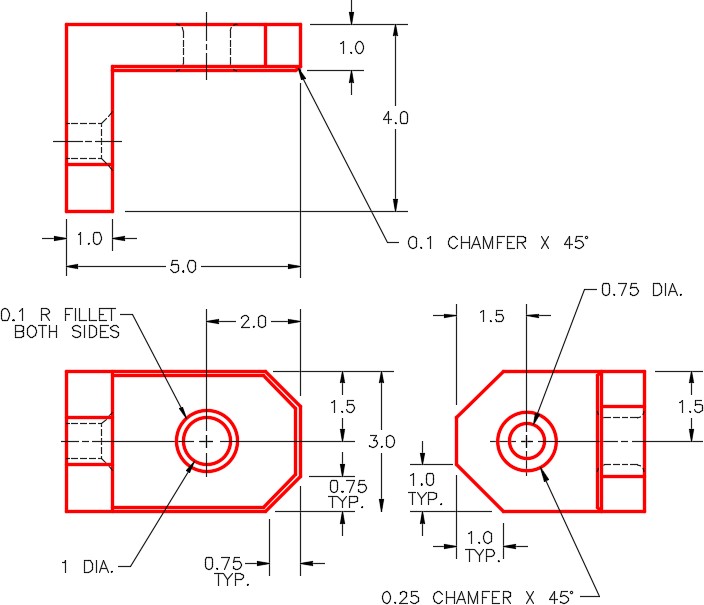
Set layer: Pline as the current layer, the current UCS to Front, the current view to SE Isometric, and the current visual style to 2D Wireframe. Create a the closed pline on the Front view using the figures as a reference. Ignore the fillets and rounds. (Figure Step 3A, 3B, and 3C)
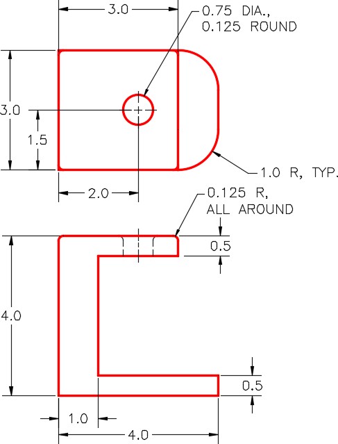
Dimensioned Multiview of Model 1
SE Isometric View
Location of 0,0,0
Step 4
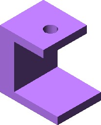
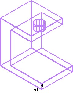
On layer: Solid 2, create a solid model as shown in the figure. Do not include the fillets and rounds. For the hole, extrude a circle. Check to ensure that your model is one solid object only using the Properties window. (Figure Step 4A and 4B)
Step 5
Turn layer: Pline off.
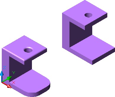
Step 6
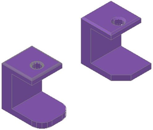
Set the current UCS to Top. Copy the solid model, that you completed in Step 4, 8 inches in the positive Y direction. The 8 inches is measured from the same point on model to the same point on the copy. The actual distance between the two model will be 5 inches. (Figure Step 6)
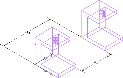
Apply Steps 7 to 10 to the model on the left side of Figure Step 6.
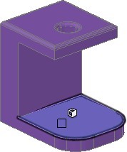
Step 7
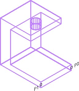
Turn layer: Pline off. Enter the FILLETEDGE command, as shown below, to fillet the bottom corners. (Figure Step 7)
Command: FILLETEDGE
Radius = 1.2500
Select an edge or [Chain/Loop/Radius]: P1
Select an edge or [Chain/Loop/Radius]: P2
Select an edge or [Chain/Loop/Radius]:
2 edge(s) selected for fillet.
Press Enter to accept the fillet or [Radius]: R
Specify Radius or [Expression] <1.0000>: 1
Press Enter to accept the fillet or [Radius]:
Command:
Step 8
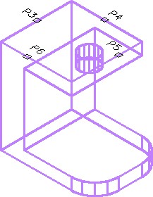
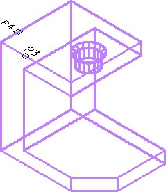
Enter the FILLETEDGE command, as shown below, to fillet the top edge. (Figure Step 8)
Command: FILLETEDGE
Radius = 1.0000
Select an edge or [Chain/Loop/Radius]: P3
select an edge or [Chain/Loop/Radius]: C
(Use the Chain option.)
Select an edge chain or [Edge/Radius]: E
Select an edge or [Chain/Loop/Radius]: P4
Select an edge or [Chain/Loop/Radius]: P5
Select an edge or [Chain/Loop/Radius]: P6
Select an edge or [Chain/Loop/Radius]: R
Enter fillet radius or [Expression] <1.0000>: .125
Select an edge or [Chain/Loop/Radius]:
4 edge(s) selected for fillet.
Press Enter to accept the fillet or [Radius]:
Command:
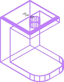
Step 9
Enter the FILLETEDGE command, as shown below, to fillet the top of the hole. (Figure Step 9)
Command: FILLETEDGE
Radius = 0.1250
Select an edge or [Chain/Loop/Radius]: P7
Select an edge or [Chain/Loop/Radius]:
1 edge(s) selected for fillet.
Press Enter to accept the fillet or [Radius]:
Command:
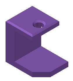
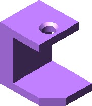
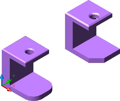
Step 10
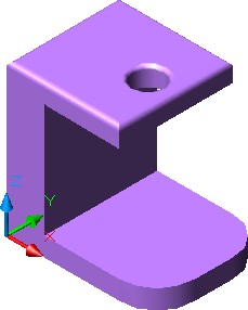
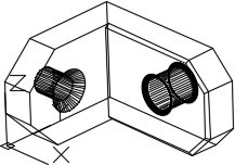
Set the visual style to Realistic. The drawing should appear as shown in the figure. (Figure Step 10)
Step 11
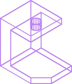
Referring to the figures, edit the model shown in Steps 11 to 13. (Figure Step 11A and 11B)
Dimensioned Multiview Of Model 2
Completed Solid Model of Model 2
– SE Isometric View
Apply Steps 12 to 14 to the model on the right side in Figure Step 6.
Step 12
Enter the CHAMFEREDGE command, as shown below, to chamfer the bottom corner. (Figure Step 12A and 12B)
Command: CHAMFEREDGE
Distance1 = 1.2500, Distance2 = 1.2500
Select an edge or [Loop/Distance]: P1
Select another edge on the same face or [Loop/Distance]: D
Specify Distance1 or [Expression] <1.0000>: 1
Specify Distance2 or [Expression] <1.0000>: 1
Select another edge on the same face or [Loop/Distance]:
Press Enter to accept the chamfer or [Distance]:
Command:
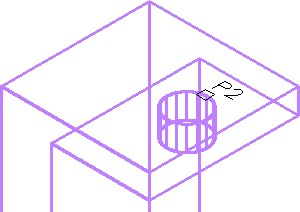
Step 13
Enter the CHAMFEREDGE command, as shown below, to chamfer the hole. (Figure Step 13A and 13B)
Command: CHAMFEREDGE
Distance1 = 1.0000, Distance2 = 1.0000
Select an edge or [Loop/Distance]: P2
Select another edge on the same face or [Loop/Distance]: D
Specify Distance1 or [Expression] <1.0000>: .15
Specify Distance2 or [Expression] <1.0000>: .15
Select another edge on the same face or [Loop/Distance]:
Press Enter to accept the chamfer or [Distance]:
Command:
Step 14
Enter the CHAMFEREDGE command, as shown below, to create a loop chamfer around the top of the model. (Figure Step 14)
Command: CHAMFEREDGE
Distance1 = 0.1500, Distance2 = 0.1500
Select an edge or [Loop/Distance]: L
Select edge of loop or [Edge/Distance]:
Enter an option [Accept/Next] <Accept>: N
Enter an option [Accept/Next] <Accept>:
Select edge of loop or [Edge/Distance]: D
Specify Distance1 or [Expression] <0.1500>: 0.125
Specify Distance2 or [Expression] <0.1500>: 0.125
Select another edge on the same face or [Loop/Distance]:
Press Enter to accept the chamfer or [Distance]:
Command:
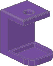
Step 15
Set the current UCS to Realistic. The final drawing should appear as shown in the figure. (Figure Step 15)
Step 16
Save and close the drawing.
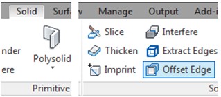
AutoCAD Command: OFFSETEDGE
The OFFSETEDGE command is used to create a closed polyline that is offset at a specified distance from the edges of a selected planar face on a 3D solid or surface.
Shortcut: none
WORK ALONG: Creating Fillets and Chamfers on Solid Models
Step 1
Open the drawing: AutoCAD 3D Workalong 19-2. Using SAVEAS, save the drawing with the name: AutoCAD 3D Workalong 19-3 (Figure Step 1)
Step 2
Set layer: Pline as the current layer.
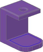
Step 3
Using the model on the left, enter the OFFSETEDGE command, as shown below, to create a closed polyline 0.25 inches from the edge. (Figure Step 3A and 3B)
Command: OFFSETEDGE
Corner = Sharp
Select face:
Specify through point or [Distance/Corner]: D
Specify distance <0.1250>: 0.25
Specify point on side to offset:
Select face:
Command:
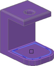
Step 4
Set layer: Solid 2 as the current layer. Enter the PRESSPULL command. When prompted, select inside the polyline and enter the height of -0.35 as shown below. (Figure Step 4A and 4B)
Command: PRESSPULL
Select object or bounded area: Specify extrusion height or [Multiple]:
Specify extrusion height or [Multiple]: -0.35
1 extrusion(s) created
Select object or bounded area:
Command:
Step 5
Save and close the drawing.
Key Principles
Key Principles in Module 19
- When constructing solid models, it is important to ensure that the completed solid model consists of one AutoCAD object.
- The INTERSECT command is used to create a solid by finding the volume shared by two or more solids.
- It is important to use the Chain option when starting a fillet on a solid model that starts and ends at the same That ensures that all the corners are filleted correctly.
- It is important to use the Loop option when starting a chamfer on a solid model that starts and ends at the same That ensures that all the corners are chamfered correctly.
Lab Exercise 19-1
Time allowed: 30 minutes.
| Drawing Name | Template | Units |
|---|---|---|
| AutoCAD 3D Lab 19-1 | 3D Layout Metric | Millimeters |
Step 1
On layer: Solid 3, draw a solid model of the object. (Figure Step 1A, 1B, and 1C)
Step 2
Draw the closed plines on layer: Pline.
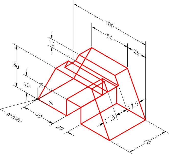
Dimensioned Wireframe Model
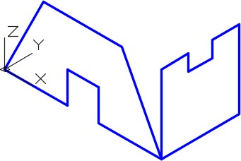
Hint
Step 3
Use the INTERSECT command and the two extruded solids to create the solid model.
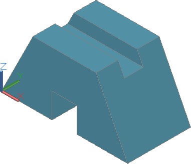
Step 4
Turn layer: Pline off and set the current visual style to Realistic.
Step 5
Set the Insertion Units, change the current UCS to World, and check the model with the key.
Step 6
Save and close the drawing.
Lab Exercise 19-2
Time allowed: 40 minutes.
| Drawing Name | Template | Units |
|---|---|---|
| AutoCAD 3D Lab 19-2 | 3D Layout Metric | Millimeters |
Step 1
Draw the closed plines on layer: Pline.
Step 2
On layer: Solid 3, draw a solid model of the object shown in the figures. (Figure Step 2A, 2B, and 2C)
Dimensioned Multiview Drawing
Hint
Step 3
Use the INTERSECT command and the two extruded solids to create the solid model.
Step 4
Add the fillets and chamfers to the solid model.
Step 5
Turn layer: Pline off and set the current visual style to Realistic.
Step 6
Set the Insertion Units, change the current UCS to World, and check the model with the key.
Step 7
Save and close the drawing.
Lab Exercise 19-3
Time allowed: 40 minutes.
| Drawing Name | Template | Units |
|---|---|---|
| AutoCAD 3D Lab 19-3 | 3D Layout English | Inches |
Step 1
Draw the closed plines on layer Pline.
Step 2
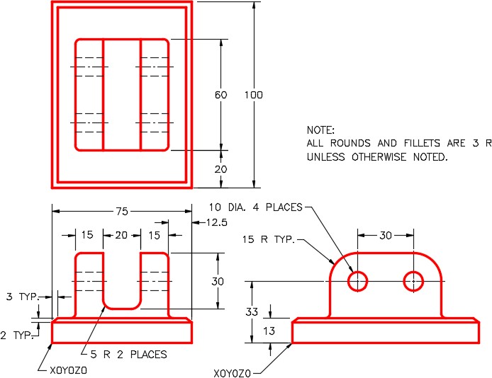
On layer: Solid 3, draw a solid model of the object shown in the figures. (Figure Step 2A, 2B, and 2C)
Dimensioned Multiview Drawing
Location of 0,0,0
Step 3
Add the fillets and chamfers to the solid model.
Step 4
Turn layer: Pline off and set the current visual style to Realistic.
Step 5
Set the Insertion Units, change the current UCS to World, and check the model with the key.
Step 6
Save and close the drawing.
Lab Exercise 19-4
Time allowed: 40 minutes.
| Drawing Name | Template | Units |
|---|---|---|
| AutoCAD 3D Lab 19-4 | 3D Layout English | Inches |
Step 1
Draw the closed plines on layer: Pline.
Step 2
On layer: Solid 4, draw a solid model of the object shown in the figures. Figure Step 2A, 2B, 2C, and 2D)
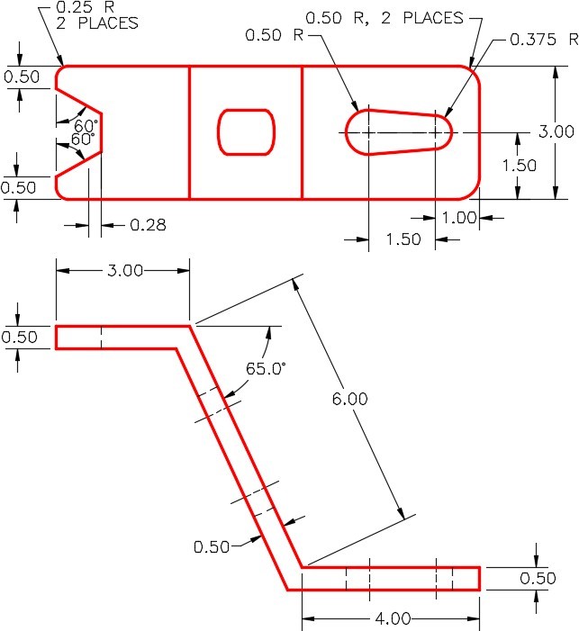
Dimensioned Multiview Drawing
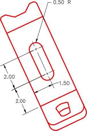
Auxiliary View
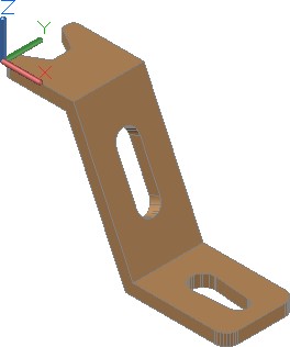
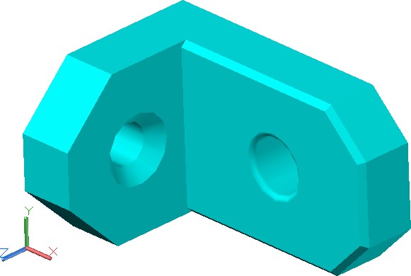
SE Isometric View
Location of 0,0,0
Step 3
Turn layer: Pline off and set the current visual style to Realistic.
Step 4
Set the Insertion Units, change the current UCS to World, and check the model with the key.
Step 5
Save and close the drawing.