
6.2: Module 23 Helix
- Page ID
- 19976

\( \newcommand{\vecs}[1]{\overset { \scriptstyle \rightharpoonup} {\mathbf{#1}} } \)
\( \newcommand{\vecd}[1]{\overset{-\!-\!\rightharpoonup}{\vphantom{a}\smash {#1}}} \)
\( \newcommand{\id}{\mathrm{id}}\) \( \newcommand{\Span}{\mathrm{span}}\)
( \newcommand{\kernel}{\mathrm{null}\,}\) \( \newcommand{\range}{\mathrm{range}\,}\)
\( \newcommand{\RealPart}{\mathrm{Re}}\) \( \newcommand{\ImaginaryPart}{\mathrm{Im}}\)
\( \newcommand{\Argument}{\mathrm{Arg}}\) \( \newcommand{\norm}[1]{\| #1 \|}\)
\( \newcommand{\inner}[2]{\langle #1, #2 \rangle}\)
\( \newcommand{\Span}{\mathrm{span}}\)
\( \newcommand{\id}{\mathrm{id}}\)
\( \newcommand{\Span}{\mathrm{span}}\)
\( \newcommand{\kernel}{\mathrm{null}\,}\)
\( \newcommand{\range}{\mathrm{range}\,}\)
\( \newcommand{\RealPart}{\mathrm{Re}}\)
\( \newcommand{\ImaginaryPart}{\mathrm{Im}}\)
\( \newcommand{\Argument}{\mathrm{Arg}}\)
\( \newcommand{\norm}[1]{\| #1 \|}\)
\( \newcommand{\inner}[2]{\langle #1, #2 \rangle}\)
\( \newcommand{\Span}{\mathrm{span}}\) \( \newcommand{\AA}{\unicode[.8,0]{x212B}}\)
\( \newcommand{\vectorA}[1]{\vec{#1}} % arrow\)
\( \newcommand{\vectorAt}[1]{\vec{\text{#1}}} % arrow\)
\( \newcommand{\vectorB}[1]{\overset { \scriptstyle \rightharpoonup} {\mathbf{#1}} } \)
\( \newcommand{\vectorC}[1]{\textbf{#1}} \)
\( \newcommand{\vectorD}[1]{\overrightarrow{#1}} \)
\( \newcommand{\vectorDt}[1]{\overrightarrow{\text{#1}}} \)
\( \newcommand{\vectE}[1]{\overset{-\!-\!\rightharpoonup}{\vphantom{a}\smash{\mathbf {#1}}}} \)
\( \newcommand{\vecs}[1]{\overset { \scriptstyle \rightharpoonup} {\mathbf{#1}} } \)
\( \newcommand{\vecd}[1]{\overset{-\!-\!\rightharpoonup}{\vphantom{a}\smash {#1}}} \)
\(\newcommand{\avec}{\mathbf a}\) \(\newcommand{\bvec}{\mathbf b}\) \(\newcommand{\cvec}{\mathbf c}\) \(\newcommand{\dvec}{\mathbf d}\) \(\newcommand{\dtil}{\widetilde{\mathbf d}}\) \(\newcommand{\evec}{\mathbf e}\) \(\newcommand{\fvec}{\mathbf f}\) \(\newcommand{\nvec}{\mathbf n}\) \(\newcommand{\pvec}{\mathbf p}\) \(\newcommand{\qvec}{\mathbf q}\) \(\newcommand{\svec}{\mathbf s}\) \(\newcommand{\tvec}{\mathbf t}\) \(\newcommand{\uvec}{\mathbf u}\) \(\newcommand{\vvec}{\mathbf v}\) \(\newcommand{\wvec}{\mathbf w}\) \(\newcommand{\xvec}{\mathbf x}\) \(\newcommand{\yvec}{\mathbf y}\) \(\newcommand{\zvec}{\mathbf z}\) \(\newcommand{\rvec}{\mathbf r}\) \(\newcommand{\mvec}{\mathbf m}\) \(\newcommand{\zerovec}{\mathbf 0}\) \(\newcommand{\onevec}{\mathbf 1}\) \(\newcommand{\real}{\mathbb R}\) \(\newcommand{\twovec}[2]{\left[\begin{array}{r}#1 \\ #2 \end{array}\right]}\) \(\newcommand{\ctwovec}[2]{\left[\begin{array}{c}#1 \\ #2 \end{array}\right]}\) \(\newcommand{\threevec}[3]{\left[\begin{array}{r}#1 \\ #2 \\ #3 \end{array}\right]}\) \(\newcommand{\cthreevec}[3]{\left[\begin{array}{c}#1 \\ #2 \\ #3 \end{array}\right]}\) \(\newcommand{\fourvec}[4]{\left[\begin{array}{r}#1 \\ #2 \\ #3 \\ #4 \end{array}\right]}\) \(\newcommand{\cfourvec}[4]{\left[\begin{array}{c}#1 \\ #2 \\ #3 \\ #4 \end{array}\right]}\) \(\newcommand{\fivevec}[5]{\left[\begin{array}{r}#1 \\ #2 \\ #3 \\ #4 \\ #5 \\ \end{array}\right]}\) \(\newcommand{\cfivevec}[5]{\left[\begin{array}{c}#1 \\ #2 \\ #3 \\ #4 \\ #5 \\ \end{array}\right]}\) \(\newcommand{\mattwo}[4]{\left[\begin{array}{rr}#1 \amp #2 \\ #3 \amp #4 \\ \end{array}\right]}\) \(\newcommand{\laspan}[1]{\text{Span}\{#1\}}\) \(\newcommand{\bcal}{\cal B}\) \(\newcommand{\ccal}{\cal C}\) \(\newcommand{\scal}{\cal S}\) \(\newcommand{\wcal}{\cal W}\) \(\newcommand{\ecal}{\cal E}\) \(\newcommand{\coords}[2]{\left\{#1\right\}_{#2}}\) \(\newcommand{\gray}[1]{\color{gray}{#1}}\) \(\newcommand{\lgray}[1]{\color{lightgray}{#1}}\) \(\newcommand{\rank}{\operatorname{rank}}\) \(\newcommand{\row}{\text{Row}}\) \(\newcommand{\col}{\text{Col}}\) \(\renewcommand{\row}{\text{Row}}\) \(\newcommand{\nul}{\text{Nul}}\) \(\newcommand{\var}{\text{Var}}\) \(\newcommand{\corr}{\text{corr}}\) \(\newcommand{\len}[1]{\left|#1\right|}\) \(\newcommand{\bbar}{\overline{\bvec}}\) \(\newcommand{\bhat}{\widehat{\bvec}}\) \(\newcommand{\bperp}{\bvec^\perp}\) \(\newcommand{\xhat}{\widehat{\xvec}}\) \(\newcommand{\vhat}{\widehat{\vvec}}\) \(\newcommand{\uhat}{\widehat{\uvec}}\) \(\newcommand{\what}{\widehat{\wvec}}\) \(\newcommand{\Sighat}{\widehat{\Sigma}}\) \(\newcommand{\lt}{<}\) \(\newcommand{\gt}{>}\) \(\newcommand{\amp}{&}\) \(\definecolor{fillinmathshade}{gray}{0.9}\)Module 23 Helix
Learning Outcomes
When you have completed this module, you will be able to:
- Describe and apply the HELIX command to create solid models of springs, coils, and threads.
Helix
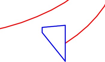
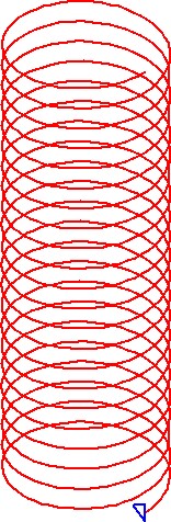
Coils, springs, and threads are constructed by drawing a profile and then using the SWEEP command, sweeping it along a path that is a helix drawn with the HELIX command. See Figure 23-1. The shape of the coil, spring or thread is controlled by the shape of the profile. See Figure 23-2, 23-3 and 23-4.
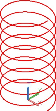
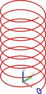
A Helix
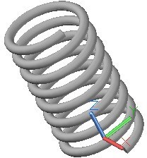
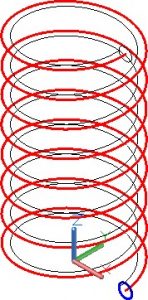
A Coil
The HELIX command is used to construct a helix. A helix is constructed by specifying one or more setting that consist of the base radius, top radius, height, number of turns, turn height or twist direction.
If the same value for both the base radius and the top radius is specified, a cylindrical helix is created. If different values are specified for the top radius and the base radius, a conical helix is created. If a height value of zero is specified, a flat 2D spiral is created.

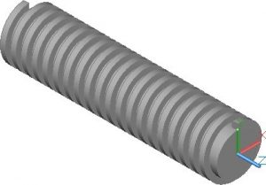
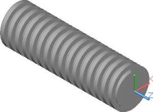
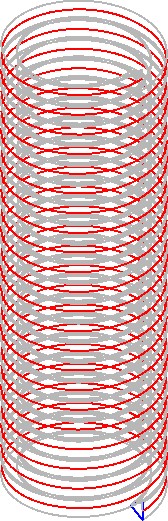
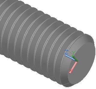
Threads
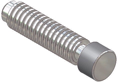
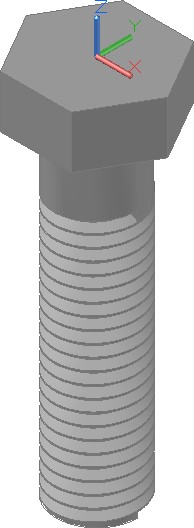
Rendered Solid Model
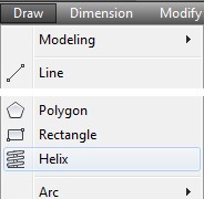
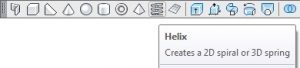
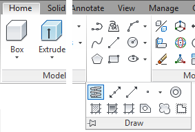
AutoCAD Command: HELIX
The HELIX command is used to create a helix.
Shortcut: none
Drafting Lesson: Springs and Threads
Study the Figure 23-5, shown below, to learn the terms used when drawing coil, springs and threads. Pitch is an important term that must be understood and is required when drawing a helix using the HELIX command. AutoCAD’s HELIX command uses the term turn height for the pitch.
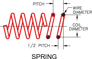
Threads and Spring Shape and Terminology
Figure 23-6 shows four common thread types and their specifications.
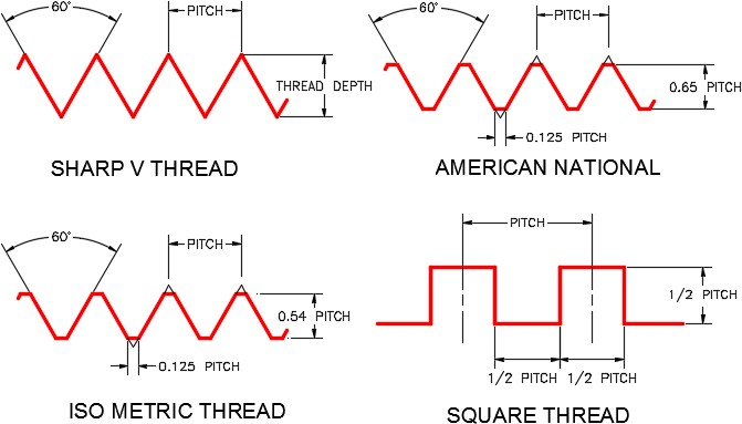
Four Common Thread Types
WORK ALONG: Creating Coils
Step 1
Using the NEW command, start a new drawing using template: 3D Layout English.
Step 2
Save and name the drawing: AutoCAD 3D Workalong 23-1. (Figure Step 2A and 2B)
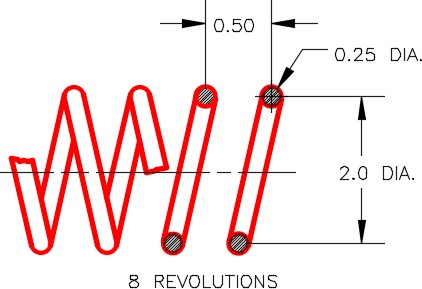
Dimensioned Drawing

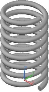
Completed Coil
Step 3
Set layer: Helix as the current layer, the current view to SE Isometric, the current UCS to Top, and the current visual style to 3D Wireframe.
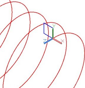
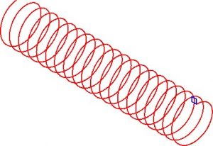
Step 4
Enter the HELIX command, as shown below, to draw the coil shown in Figure Step 2A. (Figure Step 4)
Command: HELIX
Number of turns = 3.0000 Twist=CCW
Specify centre point of base: 0,0,0
Specify base radius or [Diameter] <0.5000>: @1,0,0
(I used coordinates to ensure that the helix start along the X axis.)
Specify top radius or [Diameter] <1.0000>: 1
(Diameter of the coil is 2 inches.)
Specify helix height or [Axis endpoint/Turns/turn Height/tWist] <4.0000>: H
Specify distance between turns <1.000>: 0.5
(The pitch is 0.5 inches.)
Specify helix height or [Axis endpoint/Turns/turn Height/tWist] <4.0000>: T
Enter number of turns <3.0000>: 8
(8 turns means that the coil is 4 inches long.)
Command:

Step 5
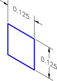
Change the current UCS to Front and set layer: Profile as the current layer. Draw a 0.25 diameter circle with its centre located at the end of the helix. (Figure Step 5)
Step 6
Set layer: Solid 8 as the current layer.
Step 7
Using what you learned in Module 22, create the coil by entering the SWEEP command. Select the circle as the profile and the helix as the path. (Figure Step 7)
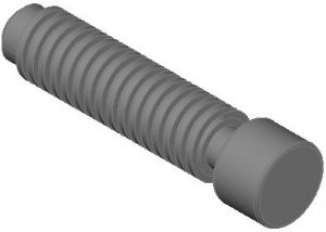
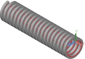
Step 8
Turn layers: Helix and Profile off. Set the current visual style to Realistic. Your completed 3D solid coil should appear as shown in the figure. (Figure Step 8)
Step 9
Save and close the drawing.
WORK ALONG: Creating Square Threads
Step 1
Using the NEW command, start a new drawing using template: 3D Layout English.
Step 2
Save and name the drawing: AutoCAD 3D Workalong 23-2. (Figure Step 2A and 2B)
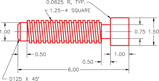
Dimensioned Multiview Drawing
Completed Solid Model – SE Isometric View
Step 3
Set layer: Pline as the current layer, the current UCS to Right, the current view to SE Isometric, and the current visual style to 3D Wireframe.
Step 4
Draw a circle, with a diameter of 1 inch. Locate its centre at 0,0,0. (Figure Step 4)

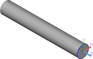
Step 5
Set layer: Solid 8 as the current layer and extrude the circle 5 inches in the negative Z direction. (Figure Step 5)
Step 6
Change the layer of the solid, that you created in Step 5, to layer: Solid Off. Turn off layers: Solid off and Pline. Set layer: Helix as the current layer.
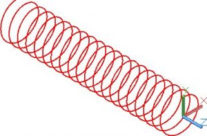
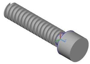
Step 7
Enter the HELIX command, as shown below, to draw a helix for the thread. (Figure Step 7)
Command: HELIX
Number of turns = 3.0000 Twist=CCW
Specify centre point of base: 0,0,0
Specify base radius or [Diameter] <1.0000>: @0,0.5,0
(This starts the helix at the top at the radius of 0.5 inches.)
Specify top radius or [Diameter] <0.5000>:
(Press Enter)
Specify helix height or [Axis endpoint/Turns/turn Height/tWist] <1.0000>: T
Enter number of turns <3.0000>: 20
(Since there are 4 turns per inch and the shaft is 5 inches long, there are 20 turns.)
Specify helix height or [Axis endpoint/Turns/turn Height/tWist] <1.0000>: A
Specify axis end point: @0,0,-5
(The end of the axis is 5 inches in the negative Z direction.)
Command:
Step 8
Set layer: Profile as the current layer and the current UCS to Front.
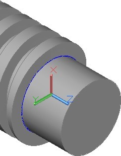
Step 9
Using the figures as a reference, draw a closed pline starting at the end of the helix. (Figure Step 9A, 9B, and 9C)
Step 10
Set layer: Solid 8 as the current layer. Using the SWEEP command, create the square thread by sweeping the profile along the helix. (Figure Step 10)
Step 11
Turn layers: Helix and Profile off. Change the solid on layer: Solid Off to layer: Solid 8.
Step 12
Using the UNION command, union the two solids to form one solid model. (Figure Step 12)
Step 13
Turn layer: Pline on and set it as the current layer.
Step 14
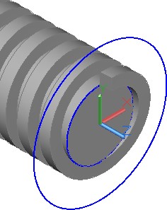
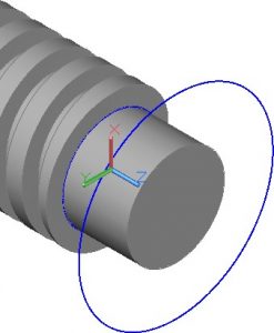
Change the current UCS to Right. Draw a 2 Inch diameter circle with its centre located at 0,0,0. (Figure Step 14)
Step 15
Change the current view to Front. (Figure Step 15)
Step 16
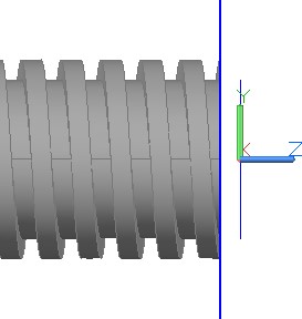
Using the MOVE command, move the 2 inch diameter circle 0.125 inches in the negative Z direction. Using the SLICE command, as shown below, slice the solid model using the 2 inch diameter circle as the Object to create a plane at the slice location. (Figure Step 16)
Command: SLICE
Select objects to slice: 1 found
(Select the solid model.)
Select objects to slice:
(Press Enter.)
Specify start point of slicing plane or [planar Object/Surface/Zaxis/View/XY/YZ/ZX/3points]
<3points>: O
Select a circle, ellipse, arc, 2D-spline, 2D-polyline to define the slicing plane:
(Select the circle.)
Specify a point on desired side or [keep Both sides] <Both>:
(Press Enter.)
Command:
Step 17
Delete the end of the solid that you sliced off. (Figure Step 17)
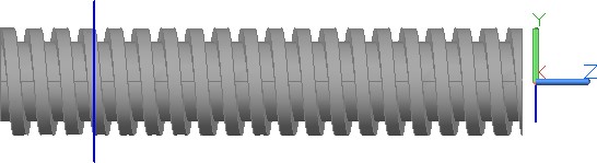
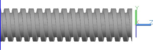
Step 18
Move the circle 4 inches in the negative Z direction. Using what you learned in the last two steps, slice the solid and delete the portion you sliced off. Set the current view to SE Isometric. (Figure Step 18A, 18B, and 18C)
Step 19
Locate the UCS at the centre of the end of the solid thread. Draw a 0.75 inch diameter circle locating the centre at 0,0,0. On layer: Solid 8, extrude the circle 0.5 inches in the positive Z direction. (Figure Step19)
Step 20
On layer: Pline, draw a 1.5 inch diameter circle locating its centre at the end of the extrusion that you created in Step 19. On layer: Solid 8, extrude the circle 1 inch in the positive Z direction. (Figure Step 20A and 20B)
Step 21
Using what you just learned, orbit the model, relocate the UCS and extrude a 1 inch diameter circle 0.5 inches in the negative Z direction. (Figure Step 21A, 21B, and 21C)
Step 22
Chamfer the end of the shaft 0.125 inches at 45 degrees. (Figure Step 22)
Step 23
Fillet the two edges of the head of the bolt using the radius 0.0625.
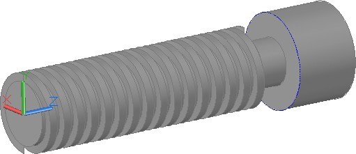
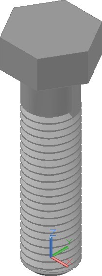
Step 24
Change the current view to SE Isometric. Using the UNION command, union the four solids to create on solid model. Your completed model should appear as shown in the figure. (Figure Step 24)
Step 25
Save and close the drawing.
WORK ALONG: Using the HELIX Command – Part 3
Step 1
Using the NEW command, start a new drawing using template: 3D Layout English.
Step 2
Save and name the drawing: AutoCAD 3D Workalong 23-3. (Figure Step 2A and 2B)
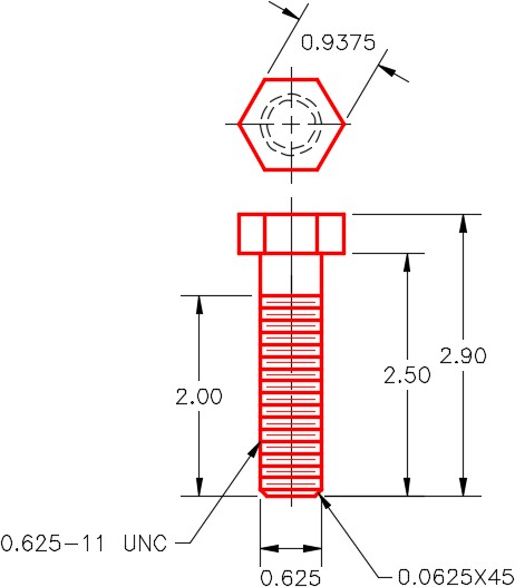
Dimensioned Multiview Drawing

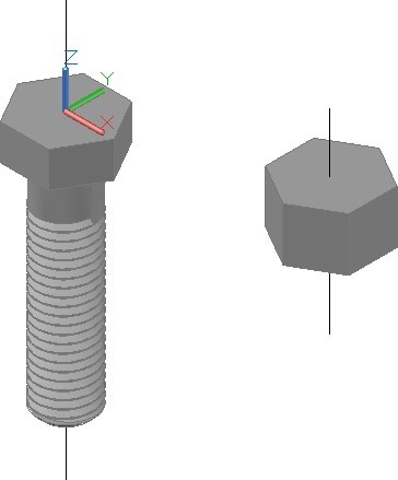
Step 3
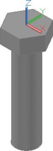
Using what you learned in the last workalong and using Figure Step 2A as a reference, draw the solid model on layer: Solid 8 to match the figure. Ensure that you union the hexagon and cylinder to create one solid model. (Figure Step 3)
Step 4
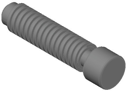
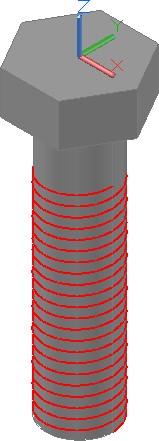
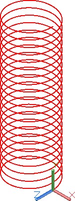
Using what you learned in the last workalong, on layer: Helix, draw the helix using the figure as a reference. (Figure Step 4A and 4B)
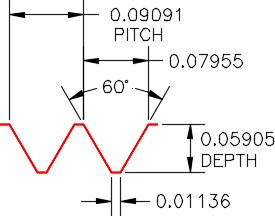
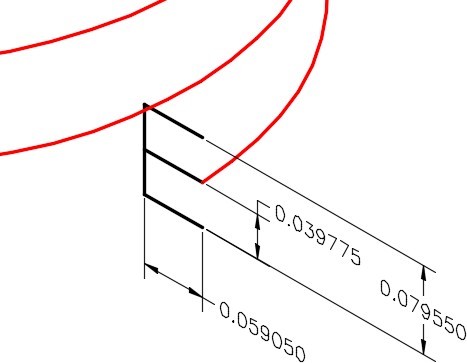
Thread Details
Step 5
Change the layer of the solid that you drew in Step 3 to layer: Solid Off. Turn off layers: Solid off and Pline.
Step 6
Set layer: Construction as the current layer and the current UCS to Front. (Figure Step 6)
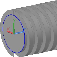
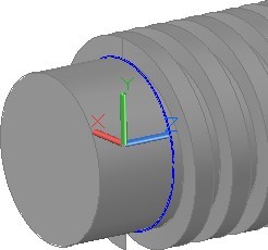
Step 7
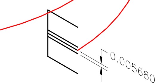
On layer: Construction, draw the construction lines for the thread profile. (Figure Step 7A and 7B)
Step 8
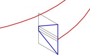
On layer: Profile, snapping to the ends of the construction lines, draw the thread profile as a closed pline. (Figure Step 8)
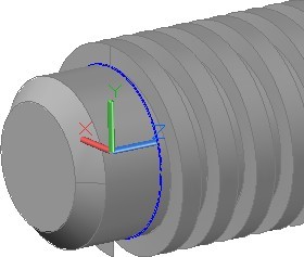
Step 9
Turn layer: Construction off. (Figure Step 9A and 9B)
Step 10
Set layer: Solid 8 as the current layer and the current UCS to Top.
Step 11
Using the SWEEP command, sweep the profile using the helix as a path. (Figure Step 11)
Step 12
Turn layers: Helix and Profile off. Change the solid from layer: Solid Off to layer: Solid 8.
Step 13
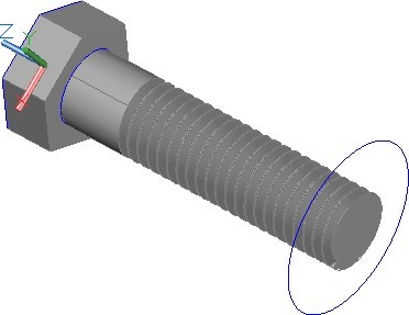
Using the SUBTRACT command, subtract the solid thread, that you created in the SWEEP command, from the solid model to create the bolt. (Figure Step 13)
Step 14
Using what you learned in the last workalong, on layer: Pline, draw 1.5 diameter circle locating its centre at the centre of the bottom of the bolt. (Figure Step 14)
Step 15
Set the current view to Front. Move the circle 0.0625 inches in the positive Z direction. (Figure Step 15)
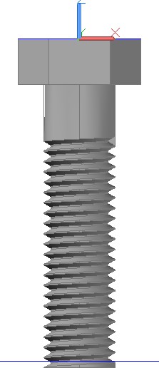
Step 16
Slice the bolt and delete the end. (Figure Step 16)
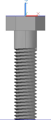
Step 17
Draw a circle at the end of the threaded shaft and extrude it 0.0625 inches. (Figure Step 17)
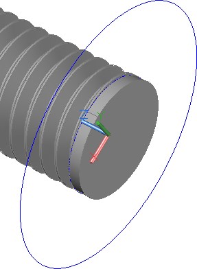
Step 18
Union the two solids together and chamfer the end of the bolt using the dimensioned drawing as a reference. (Figure Step 18A and 18B)
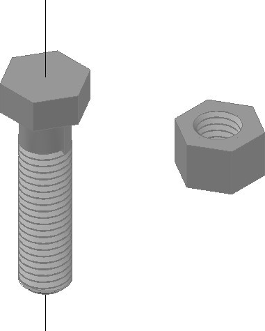
Step 19
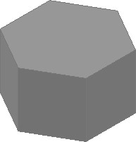
On layer: Solid 8, anywhere in model space, draw the solid model of the nut to match the figure. Do not draw the hole in the centre. (Figure Step 19A and 19B)
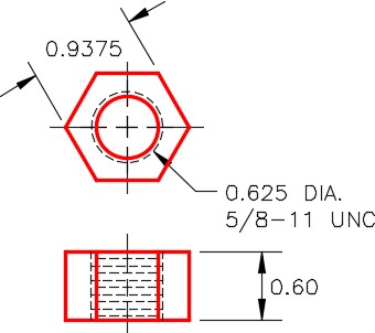
Dimensioned Multiview Drawing
Step 20
On layer: Center Line, draw a line on the centerline of the bolt and the nut. The length of the lines is not important. (Figure Step 20)
Step 21
Using the centerlines to snap to, copy the bolt exactly in the centre of the nut. The vertical location is not important as long as the nut is totally in the threaded area. (Figure Step 21)
Step 22
Using the SUBTRACT command, Subtract the bolt from the nut to leave the nut threaded. (Figure Step 22)
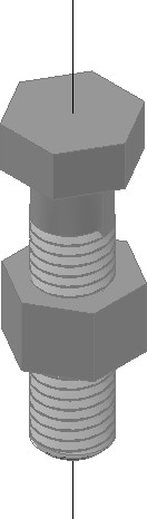
Step 23
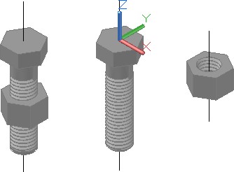
Using the centerlines, copy the solid models to create an assembly solid model. After you assemble the two parts by snapping to the centerlines, with Ortho enabled, move the nut, by eye, to locate it vertically. Do not union the bolt and nut together. (Figure Step 23A and 23B)
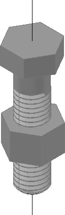
Step 24
Save and close the drawing.
Key Principles
Key Principles in Module 23
- Coils, springs and threads are constructed by drawing a profile and then using the SWEEP command, sweeping it along a path that is a helix drawn with the HELIX command.
- A helix is constructed by specifying one or more setting that consist of the base radius, top radius, height, number of turns, turn height or twist direction.