
6.3: Module 24 Loft
- Page ID
- 19978

\( \newcommand{\vecs}[1]{\overset { \scriptstyle \rightharpoonup} {\mathbf{#1}} } \)
\( \newcommand{\vecd}[1]{\overset{-\!-\!\rightharpoonup}{\vphantom{a}\smash {#1}}} \)
\( \newcommand{\id}{\mathrm{id}}\) \( \newcommand{\Span}{\mathrm{span}}\)
( \newcommand{\kernel}{\mathrm{null}\,}\) \( \newcommand{\range}{\mathrm{range}\,}\)
\( \newcommand{\RealPart}{\mathrm{Re}}\) \( \newcommand{\ImaginaryPart}{\mathrm{Im}}\)
\( \newcommand{\Argument}{\mathrm{Arg}}\) \( \newcommand{\norm}[1]{\| #1 \|}\)
\( \newcommand{\inner}[2]{\langle #1, #2 \rangle}\)
\( \newcommand{\Span}{\mathrm{span}}\)
\( \newcommand{\id}{\mathrm{id}}\)
\( \newcommand{\Span}{\mathrm{span}}\)
\( \newcommand{\kernel}{\mathrm{null}\,}\)
\( \newcommand{\range}{\mathrm{range}\,}\)
\( \newcommand{\RealPart}{\mathrm{Re}}\)
\( \newcommand{\ImaginaryPart}{\mathrm{Im}}\)
\( \newcommand{\Argument}{\mathrm{Arg}}\)
\( \newcommand{\norm}[1]{\| #1 \|}\)
\( \newcommand{\inner}[2]{\langle #1, #2 \rangle}\)
\( \newcommand{\Span}{\mathrm{span}}\) \( \newcommand{\AA}{\unicode[.8,0]{x212B}}\)
\( \newcommand{\vectorA}[1]{\vec{#1}} % arrow\)
\( \newcommand{\vectorAt}[1]{\vec{\text{#1}}} % arrow\)
\( \newcommand{\vectorB}[1]{\overset { \scriptstyle \rightharpoonup} {\mathbf{#1}} } \)
\( \newcommand{\vectorC}[1]{\textbf{#1}} \)
\( \newcommand{\vectorD}[1]{\overrightarrow{#1}} \)
\( \newcommand{\vectorDt}[1]{\overrightarrow{\text{#1}}} \)
\( \newcommand{\vectE}[1]{\overset{-\!-\!\rightharpoonup}{\vphantom{a}\smash{\mathbf {#1}}}} \)
\( \newcommand{\vecs}[1]{\overset { \scriptstyle \rightharpoonup} {\mathbf{#1}} } \)
\( \newcommand{\vecd}[1]{\overset{-\!-\!\rightharpoonup}{\vphantom{a}\smash {#1}}} \)
\(\newcommand{\avec}{\mathbf a}\) \(\newcommand{\bvec}{\mathbf b}\) \(\newcommand{\cvec}{\mathbf c}\) \(\newcommand{\dvec}{\mathbf d}\) \(\newcommand{\dtil}{\widetilde{\mathbf d}}\) \(\newcommand{\evec}{\mathbf e}\) \(\newcommand{\fvec}{\mathbf f}\) \(\newcommand{\nvec}{\mathbf n}\) \(\newcommand{\pvec}{\mathbf p}\) \(\newcommand{\qvec}{\mathbf q}\) \(\newcommand{\svec}{\mathbf s}\) \(\newcommand{\tvec}{\mathbf t}\) \(\newcommand{\uvec}{\mathbf u}\) \(\newcommand{\vvec}{\mathbf v}\) \(\newcommand{\wvec}{\mathbf w}\) \(\newcommand{\xvec}{\mathbf x}\) \(\newcommand{\yvec}{\mathbf y}\) \(\newcommand{\zvec}{\mathbf z}\) \(\newcommand{\rvec}{\mathbf r}\) \(\newcommand{\mvec}{\mathbf m}\) \(\newcommand{\zerovec}{\mathbf 0}\) \(\newcommand{\onevec}{\mathbf 1}\) \(\newcommand{\real}{\mathbb R}\) \(\newcommand{\twovec}[2]{\left[\begin{array}{r}#1 \\ #2 \end{array}\right]}\) \(\newcommand{\ctwovec}[2]{\left[\begin{array}{c}#1 \\ #2 \end{array}\right]}\) \(\newcommand{\threevec}[3]{\left[\begin{array}{r}#1 \\ #2 \\ #3 \end{array}\right]}\) \(\newcommand{\cthreevec}[3]{\left[\begin{array}{c}#1 \\ #2 \\ #3 \end{array}\right]}\) \(\newcommand{\fourvec}[4]{\left[\begin{array}{r}#1 \\ #2 \\ #3 \\ #4 \end{array}\right]}\) \(\newcommand{\cfourvec}[4]{\left[\begin{array}{c}#1 \\ #2 \\ #3 \\ #4 \end{array}\right]}\) \(\newcommand{\fivevec}[5]{\left[\begin{array}{r}#1 \\ #2 \\ #3 \\ #4 \\ #5 \\ \end{array}\right]}\) \(\newcommand{\cfivevec}[5]{\left[\begin{array}{c}#1 \\ #2 \\ #3 \\ #4 \\ #5 \\ \end{array}\right]}\) \(\newcommand{\mattwo}[4]{\left[\begin{array}{rr}#1 \amp #2 \\ #3 \amp #4 \\ \end{array}\right]}\) \(\newcommand{\laspan}[1]{\text{Span}\{#1\}}\) \(\newcommand{\bcal}{\cal B}\) \(\newcommand{\ccal}{\cal C}\) \(\newcommand{\scal}{\cal S}\) \(\newcommand{\wcal}{\cal W}\) \(\newcommand{\ecal}{\cal E}\) \(\newcommand{\coords}[2]{\left\{#1\right\}_{#2}}\) \(\newcommand{\gray}[1]{\color{gray}{#1}}\) \(\newcommand{\lgray}[1]{\color{lightgray}{#1}}\) \(\newcommand{\rank}{\operatorname{rank}}\) \(\newcommand{\row}{\text{Row}}\) \(\newcommand{\col}{\text{Col}}\) \(\renewcommand{\row}{\text{Row}}\) \(\newcommand{\nul}{\text{Nul}}\) \(\newcommand{\var}{\text{Var}}\) \(\newcommand{\corr}{\text{corr}}\) \(\newcommand{\len}[1]{\left|#1\right|}\) \(\newcommand{\bbar}{\overline{\bvec}}\) \(\newcommand{\bhat}{\widehat{\bvec}}\) \(\newcommand{\bperp}{\bvec^\perp}\) \(\newcommand{\xhat}{\widehat{\xvec}}\) \(\newcommand{\vhat}{\widehat{\vvec}}\) \(\newcommand{\uhat}{\widehat{\uvec}}\) \(\newcommand{\what}{\widehat{\wvec}}\) \(\newcommand{\Sighat}{\widehat{\Sigma}}\) \(\newcommand{\lt}{<}\) \(\newcommand{\gt}{>}\) \(\newcommand{\amp}{&}\) \(\definecolor{fillinmathshade}{gray}{0.9}\)Module 24 Loft
Learning Outcomes
When you have completed this module, you will be able to:
- Describe and apply the LOFT command to create solid or surface models by blending them between two or more cross sections.
Loft
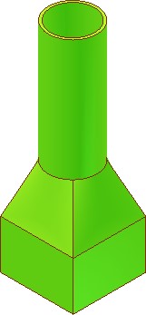
A loft is a blend or transition solid or surface that connects two or more cross sections. The cross sections, also called profiles, can be the same or different shapes. See Figure 24-1. The cross sections can also be projected along a path.
The most common drawing objects that can be used for the cross sections are 2D and 3D splines, 2D polylines, 2D solids, arcs, circles, ellipses, elliptical arcs, and lines. For a complete list, see the AutoCAD Help files.
The path must be a single open or closed object. The most common objects that can be used for the path are 2D and 3D splines, 2D and 3D polylines, helices, arcs, circles, ellipses, elliptical arcs, and lines. See AutoCAD’s Help.
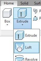
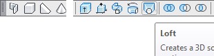
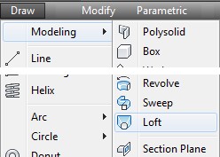
A Loft
AutoCAD Command: LOFT
The LOFT command is used to create a solid or surface by blending two or more cross sections with the same or different shapes.
Shortcut: none
WORK ALONG: Using the LOFT Command
Step 1
Using the NEW command, start a new drawing using template: 3D Layout English.
Step 2
Save and name the drawing: AutoCAD 3D Workalong 24-1.
Step 3
Set the current visual style to 3D Wireframe, the current layer to Profile, the current view to SE Isometric, and the current UCS to Right.
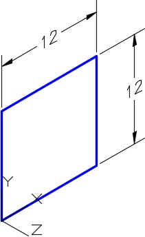
Step 4
Using Figure Step 4A as a reference, draw a 12 × 12 inch closed pline. Start the bottom left corner at 0,0,0 as shown in the figure. (Figure Step 4A and 4B)
Step 5
Using the Properties window, ensure that the square is a closed pline.
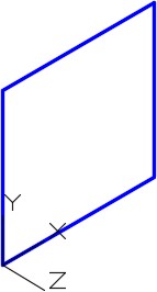
Step 6
Copy the closed pline 6 inches in the positive Z direction. (Figure Step 6)
Step 7
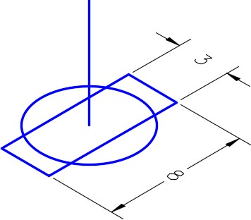
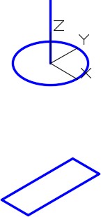
Draw a 6 inch diameter circle exactly in the centre of the copied square. (Figure Step 7)
Step 8
Move the circle 8 inches in the positive Z direction. (Figure Step 8)
Step 9
Change the current UCS to Front and the set layer: Path as the current layer.
Step 10
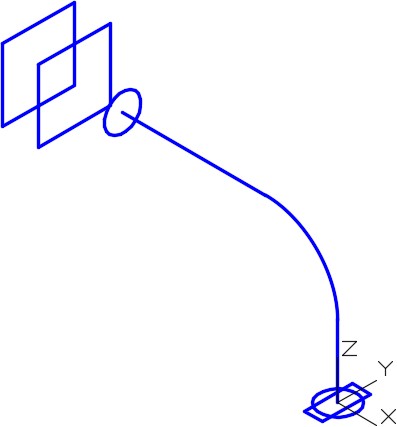
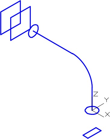
Draw a pline 36 inches in the positive X direction and then 24 inches in the negative Y direction. Start it at the centre of the circle. (Figure Step 10)
Step 11
Fillet the pline with a radius of 12 inches. (Figure Step 11)
Step 12
Change the current UCS to Top and the set layer: Profile as current layer.
Step 13
Draw a 6 diameter circle locating its centre at the bottom end of the pline that you just drew. (Figure Step 13)
Step 14
After drawing the necessary construction lines, draw a 3 x 8 closed rectangular pline with its centre located at the end of the pline. (Figure Step 14A and 14B)
Step 15
Move the rectangular pline 10 inches in the negative Z direction. (Figure Step 15)
Step 16
Set the current view to SE Isometric. (Figure Step 16)
Step 17
Ensure that the system variable DELOBJ is set to 0.
Step 18
Set the current layer to Solid 4 and the system variable ISOLINES to 4.
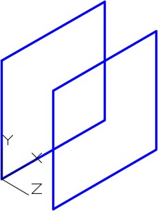
Step 19
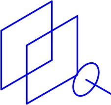
Enter the LOFT command, as shown below, and select the two squares for the cross sections. (Figure Step 19)
Command: LOFT
Current wire frame density: ISOLINES=4, Closed profiles creation mode = Solid
Select cross sections in lofting order or [POint/Join multiple edges/MOde]: 1 found
Select cross sections in lofting order or [POint/Join multiple edges/MOde]: 1 found, 2 total
Select cross sections in lofting order or [POint/Join multiple edges/MOde]: 2 cross sections selected
Enter an option [Guides/Path/Cross sections only/Settings] <Cross sections only>:
(Press Enter)
Command:
Step 20
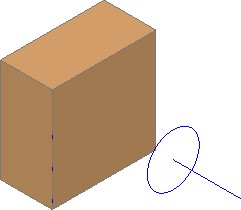
Turn off layer: Solid Off. Change the layer of the solid that you just created in Step 18 to layer: Solid Off. (Figure Step 20)
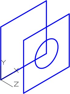
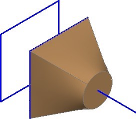
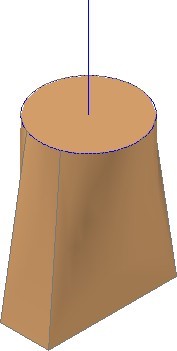
Step 21
Using the LOFT command, create a loft selecting the square and circle as the cross sections. (Figure Step 21)
Step 22
Change the layer of the solid that you just created in the loft to layer: Solid Off.
Step 23
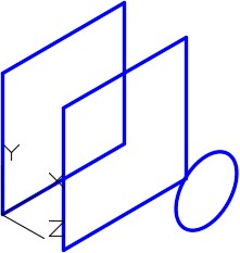
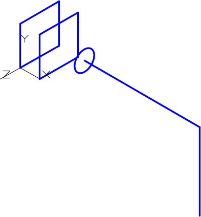
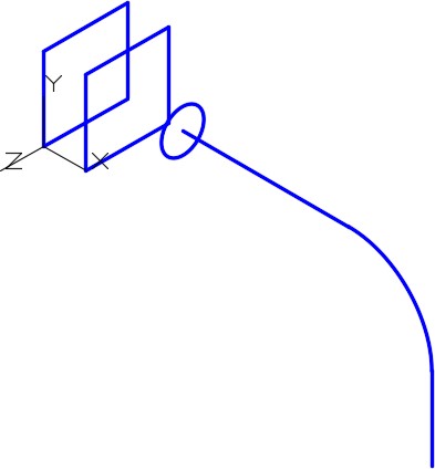
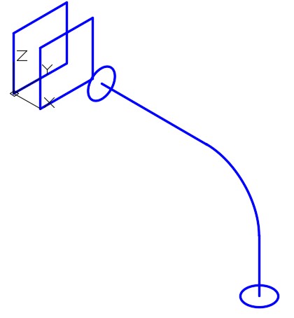
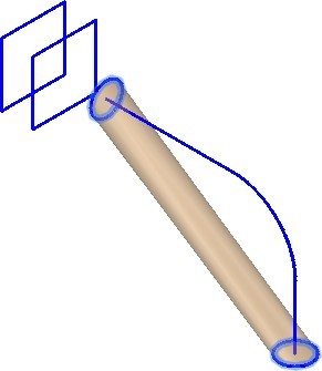
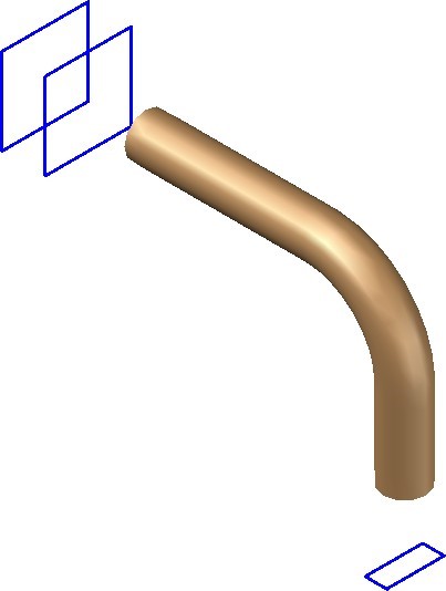
Enter the LOFT command, as shown below, to draw a loft between two cross sections that follow a path. Select the two circles for the cross sections, and the pline as the path. (Figure Step 23A and 23B)
Command: LOFT
Current wire frame density: ISOLINES=4, Closed profiles creation mode = Solid
Select cross sections in lofting order or [Point/Join multiple edges/MOde]: 1 found
Select cross sections in lofting order or [POint/Join multiple edges/MOde]: 1 found,2 total
Select cross sections in lofting order or [POint/Join multiple edges/MOde]: 2 cross sections selected
Enter an option [Guides/Path/Cross sections only/Settings] <Cross sections only>: P
Select path profile: 1 found
(Select the pline.)
Command:
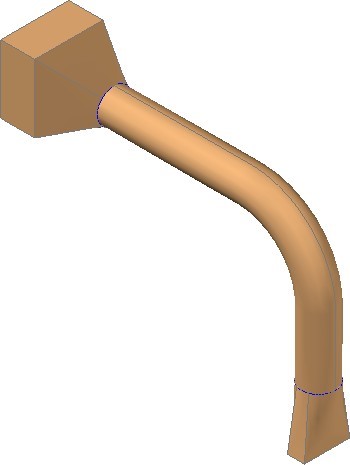
Step 24
Using what you already learned in the workalong, change the layer of the solid created in Step 23 to layer: Solid off. Create a solid using the loft command between the circle and the rectangle. (Figure Step 24)
Step 25
Turn off layers: Profile and Path.
Step 26
Change the layer of all solids, that are on layer: Solid Off, to layer: Solid 4.
Step 27
Using the UNION command, union all solids to form a single solid. (Figure Step 27)
Step 28
Save and close the drawing.
Key Principles
Key Principles in Module 24
- A loft, created with the LOFT command, is a blend or transition solid or surface that connects two or more cross sections. The cross sections, sometimes called profiles, can be the same or different shapes. The cross sections can also be projected along a path.
Lab Exercise 24-1
Time allowed: 60 minutes.
| Drawing Name | Template | Units |
|---|---|---|
| AutoCAD 3D Lab 24-1 | 3D Layout Metric | Millimeters |
Step 1
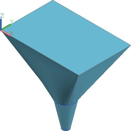
On layer: Solid 3, draw a solid model of the object shown in the figure by drawing cross sections and then using the LOFT command. (Figure Step 1)
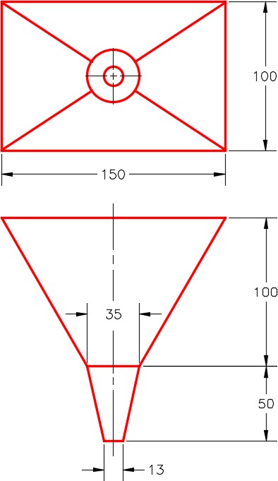
Dimensioned Multiview Drawing
Step 2
Draw the cross sections on layer: Profile.
Step 3
Union the solids to create one single solid model. (Figure Step 3)
Step 4
Save and close the drawing.
Lab Exercise 24-2
Time allowed: 60 minutes.
| Drawing Name | Template | Units |
|---|---|---|
| AutoCAD 3D Lab 24-2 | 3D Layout English | Inches |
Step 1
On layer: Solid 2, draw a solid model of the object shown in the figure by drawing cross sections and then using the LOFT command. (Figure Step 1)
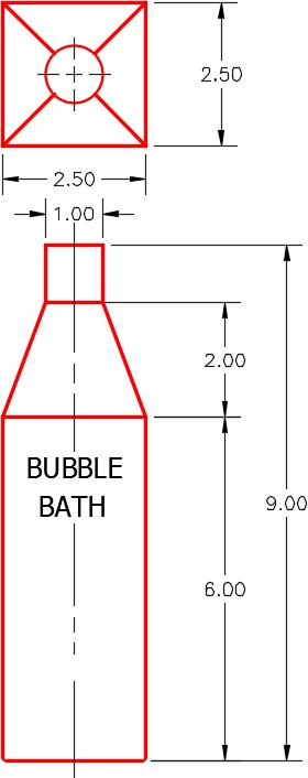
Dimensioned Multiview Drawing
Step 2
Draw the cross sections on layer: Profile.
Step 3
Draw the text on layer: Text after you create the solid. Use the font: Tohoma. Select the height of your choice.
Step 4
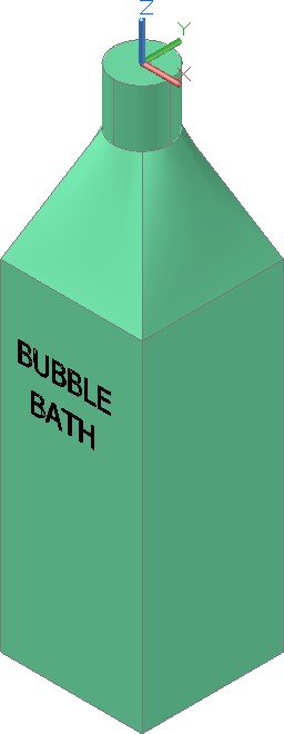
Union the solids together to create one single solid model. (Figure Step 4)
Step 5
Save and close the drawing.