1.4: Module 4 Sketching Lines
- Page ID
- 19868

\( \newcommand{\vecs}[1]{\overset { \scriptstyle \rightharpoonup} {\mathbf{#1}} } \)
\( \newcommand{\vecd}[1]{\overset{-\!-\!\rightharpoonup}{\vphantom{a}\smash {#1}}} \)
\( \newcommand{\id}{\mathrm{id}}\) \( \newcommand{\Span}{\mathrm{span}}\)
( \newcommand{\kernel}{\mathrm{null}\,}\) \( \newcommand{\range}{\mathrm{range}\,}\)
\( \newcommand{\RealPart}{\mathrm{Re}}\) \( \newcommand{\ImaginaryPart}{\mathrm{Im}}\)
\( \newcommand{\Argument}{\mathrm{Arg}}\) \( \newcommand{\norm}[1]{\| #1 \|}\)
\( \newcommand{\inner}[2]{\langle #1, #2 \rangle}\)
\( \newcommand{\Span}{\mathrm{span}}\)
\( \newcommand{\id}{\mathrm{id}}\)
\( \newcommand{\Span}{\mathrm{span}}\)
\( \newcommand{\kernel}{\mathrm{null}\,}\)
\( \newcommand{\range}{\mathrm{range}\,}\)
\( \newcommand{\RealPart}{\mathrm{Re}}\)
\( \newcommand{\ImaginaryPart}{\mathrm{Im}}\)
\( \newcommand{\Argument}{\mathrm{Arg}}\)
\( \newcommand{\norm}[1]{\| #1 \|}\)
\( \newcommand{\inner}[2]{\langle #1, #2 \rangle}\)
\( \newcommand{\Span}{\mathrm{span}}\) \( \newcommand{\AA}{\unicode[.8,0]{x212B}}\)
\( \newcommand{\vectorA}[1]{\vec{#1}} % arrow\)
\( \newcommand{\vectorAt}[1]{\vec{\text{#1}}} % arrow\)
\( \newcommand{\vectorB}[1]{\overset { \scriptstyle \rightharpoonup} {\mathbf{#1}} } \)
\( \newcommand{\vectorC}[1]{\textbf{#1}} \)
\( \newcommand{\vectorD}[1]{\overrightarrow{#1}} \)
\( \newcommand{\vectorDt}[1]{\overrightarrow{\text{#1}}} \)
\( \newcommand{\vectE}[1]{\overset{-\!-\!\rightharpoonup}{\vphantom{a}\smash{\mathbf {#1}}}} \)
\( \newcommand{\vecs}[1]{\overset { \scriptstyle \rightharpoonup} {\mathbf{#1}} } \)
\( \newcommand{\vecd}[1]{\overset{-\!-\!\rightharpoonup}{\vphantom{a}\smash {#1}}} \)
\(\newcommand{\avec}{\mathbf a}\) \(\newcommand{\bvec}{\mathbf b}\) \(\newcommand{\cvec}{\mathbf c}\) \(\newcommand{\dvec}{\mathbf d}\) \(\newcommand{\dtil}{\widetilde{\mathbf d}}\) \(\newcommand{\evec}{\mathbf e}\) \(\newcommand{\fvec}{\mathbf f}\) \(\newcommand{\nvec}{\mathbf n}\) \(\newcommand{\pvec}{\mathbf p}\) \(\newcommand{\qvec}{\mathbf q}\) \(\newcommand{\svec}{\mathbf s}\) \(\newcommand{\tvec}{\mathbf t}\) \(\newcommand{\uvec}{\mathbf u}\) \(\newcommand{\vvec}{\mathbf v}\) \(\newcommand{\wvec}{\mathbf w}\) \(\newcommand{\xvec}{\mathbf x}\) \(\newcommand{\yvec}{\mathbf y}\) \(\newcommand{\zvec}{\mathbf z}\) \(\newcommand{\rvec}{\mathbf r}\) \(\newcommand{\mvec}{\mathbf m}\) \(\newcommand{\zerovec}{\mathbf 0}\) \(\newcommand{\onevec}{\mathbf 1}\) \(\newcommand{\real}{\mathbb R}\) \(\newcommand{\twovec}[2]{\left[\begin{array}{r}#1 \\ #2 \end{array}\right]}\) \(\newcommand{\ctwovec}[2]{\left[\begin{array}{c}#1 \\ #2 \end{array}\right]}\) \(\newcommand{\threevec}[3]{\left[\begin{array}{r}#1 \\ #2 \\ #3 \end{array}\right]}\) \(\newcommand{\cthreevec}[3]{\left[\begin{array}{c}#1 \\ #2 \\ #3 \end{array}\right]}\) \(\newcommand{\fourvec}[4]{\left[\begin{array}{r}#1 \\ #2 \\ #3 \\ #4 \end{array}\right]}\) \(\newcommand{\cfourvec}[4]{\left[\begin{array}{c}#1 \\ #2 \\ #3 \\ #4 \end{array}\right]}\) \(\newcommand{\fivevec}[5]{\left[\begin{array}{r}#1 \\ #2 \\ #3 \\ #4 \\ #5 \\ \end{array}\right]}\) \(\newcommand{\cfivevec}[5]{\left[\begin{array}{c}#1 \\ #2 \\ #3 \\ #4 \\ #5 \\ \end{array}\right]}\) \(\newcommand{\mattwo}[4]{\left[\begin{array}{rr}#1 \amp #2 \\ #3 \amp #4 \\ \end{array}\right]}\) \(\newcommand{\laspan}[1]{\text{Span}\{#1\}}\) \(\newcommand{\bcal}{\cal B}\) \(\newcommand{\ccal}{\cal C}\) \(\newcommand{\scal}{\cal S}\) \(\newcommand{\wcal}{\cal W}\) \(\newcommand{\ecal}{\cal E}\) \(\newcommand{\coords}[2]{\left\{#1\right\}_{#2}}\) \(\newcommand{\gray}[1]{\color{gray}{#1}}\) \(\newcommand{\lgray}[1]{\color{lightgray}{#1}}\) \(\newcommand{\rank}{\operatorname{rank}}\) \(\newcommand{\row}{\text{Row}}\) \(\newcommand{\col}{\text{Col}}\) \(\renewcommand{\row}{\text{Row}}\) \(\newcommand{\nul}{\text{Nul}}\) \(\newcommand{\var}{\text{Var}}\) \(\newcommand{\corr}{\text{corr}}\) \(\newcommand{\len}[1]{\left|#1\right|}\) \(\newcommand{\bbar}{\overline{\bvec}}\) \(\newcommand{\bhat}{\widehat{\bvec}}\) \(\newcommand{\bperp}{\bvec^\perp}\) \(\newcommand{\xhat}{\widehat{\xvec}}\) \(\newcommand{\vhat}{\widehat{\vvec}}\) \(\newcommand{\uhat}{\widehat{\uvec}}\) \(\newcommand{\what}{\widehat{\wvec}}\) \(\newcommand{\Sighat}{\widehat{\Sigma}}\) \(\newcommand{\lt}{<}\) \(\newcommand{\gt}{>}\) \(\newcommand{\amp}{&}\) \(\definecolor{fillinmathshade}{gray}{0.9}\)4
Module 4 Sketching Lines
Wally Baumback
idLearning Outcomes
When you have completed this module, you will be able to:
- Describe the Cartesian Coordinate System, parametric solid modeling, the Base sketch, and geometrical constraints.
- Describe snapping onto grids, lines, endpoints, and midpoints.
- Describe and apply the PROJECT GEOMETRY command to project the Center Point onto the Base sketch.
- Following Inventors 2D sketching rules, describe and apply the LINE command to draw the Base sketch of simple solid models.
Geometry Lesson: Points and Lines
A point is defined as a single XY coordinate. It does not have width, height, or depth. A line is the shortest distance between two XY coordinates. Lines can be horizontal, vertical, or inclined. Lines that are the same distance apart are called parallel lines. Perpendicular lines are at right angles to each other or 90 degrees apart. See Figure 4-1 and 4-2.
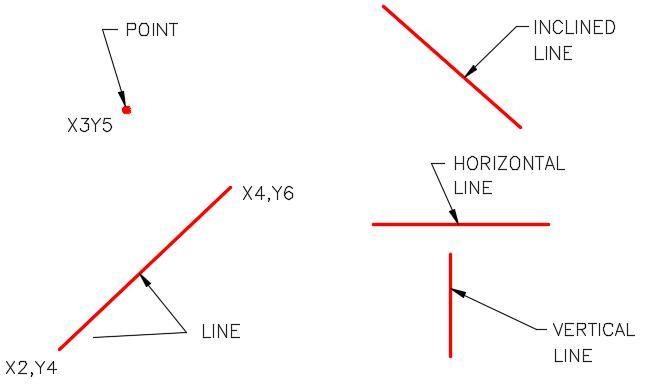
Points and Lines [Click to see image full size]
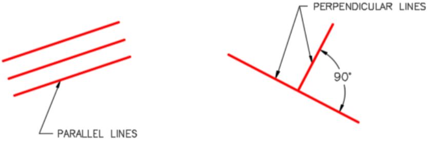
Parallel and Perpendicular Lines [Click to see image full size]
The Cartesian Coordinate System
To accurately draw two dimensional (2D) Base sketches, you must understand the Cartesian Coordinate System.
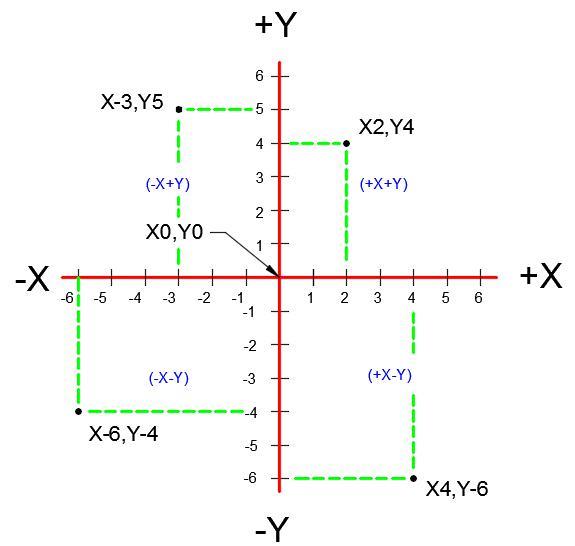
The Cartesian Coordinate System [Click to see image full size]
The Cartesian Coordinate System consists of two numbered lines crossing perpendicular to one another at their zero values. The horizontal axis is the X axis and the vertical axis is the Y axis. See Figure 4-3. A coordinate value is assigned to each location on the current construction plane. Each coordinate value consists of a pair of numbers, the first is the X coordinate and the second is the Y coordinate, written X,Y. The X and Y values are separated by a comma. For example, X2,Y4 is the location 2 units to the right and 4 units up from X0,Y0 or 0,0.
The values can be either positive or negative. Positive numbers are default so the plus sign is not required. If the value is negative, the minus sign must precede the number. For example, -3,5 is X minus 3 and Y positive 5.
Parametric Solid Modeling
Inventor is a true Three Dimensional Parametric Solid Modeling system. A parametric solid model is a 3 dimensional solid model designed with geometrical and dimensional constraints rather then hard dimensions. A model designed in this way can then be modified by changing the dimensions, and/or constraints during or after the design is complete. When one or more constraints are modified, all other dependant constraints will automatically modify the model to conform to the new constraints. Geometric constraints are taught in this modules and dimensional constraints are taught in Module 5.
Geometrical Constraints
Geometrical constraints are used to apply geometrical relationships to the objects in the 2D sketch. They specify the geometrical relationship that the objects have to the sketching plane and to one another. Relationships like horizontal, vertical, parallel, or perpendicular are used. By applying geometrical constraints the number of dimensional constraints required to fully constrain the model is reduced. Applying the correct geometrical constraints prevents unwanted changes to a feature when geometry or dimensions are modified.
Since the geometrical constraint symbol displays and the constraints are automatically applied as the sketch is drawn, you have control on which constraints are applied to the objects as you are drawing the sketch. Constraints can be added while creating the sketch or by editing the sketch after the solid model is constructed. The geometrical constraints taught in this module are shown in Figure 4-4. Additional geometrical constraints will be taught throughout the Inventor book.
USER TIP: If you draw an incorrect line, you can click the Undo icon to remove it and insert it again. See Module 2, Undo and Redo Commands. It is sometimes easier to undo rather than deleting the line. This will only work if you click Undo icon immediately after you inserted the line and have not exited the LINE command.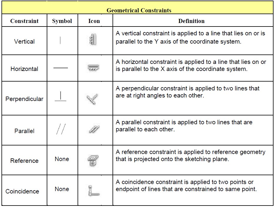
Geometrical Constraints
Projecting Reference Geometry
Projected reference geometry is geometry that has its position fixed relative to the sketching plane it resides on. Objects in the sketch are constrained with geometrical or dimensional constraints to the reference geometry to constrain it to the sketching plane. If the objects in the sketch are not constrained to the sketching plane, they will free float. A sketch that is not constrained to the sketching plane can never be fully constrained.
Inventor allows reference geometry to be projected in many different methods and uses. Many of these methods will be covered in the Inventor book. In this module, projecting the Center Point onto the plane of the Base sketch is taught.
Snapping
It is absolutely imperative that, when required, you snap to grids or locations on objects when drawing 2D sketches. Snapping to these locations ensures that the sketch is drawn accurately and constrained correctly. Inventor has many different snapping locations and they will be taught throughout the Inventor book. For now, the snap locations shown in Figure 4-5 should be used when drawing sketches. Study the figure before starting the workalong.
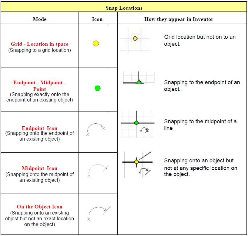
Snap Locations and Symbols
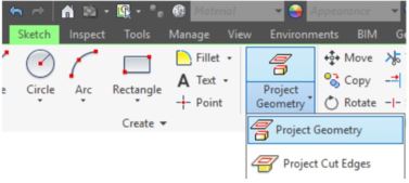
Inventor Command: PROJECT GEOMETRY
The PROJECT GEOMETRY command is used to project geometry to a fixed position on the 2D sketch plane.
Shortcut: none
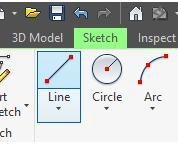
Inventor Command: LINE
The LINE command is used to draw lines on a sketch.
Shortcut: L

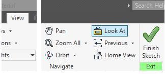
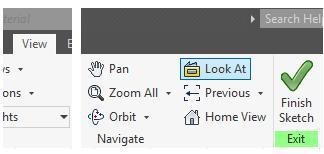
Inventor Command: LOOK AT
The LOOK AT command is used to change the users viewpoint to view the model or sketch perpendicular to the selected object, edge, or plane.
Shortcut: PAGE UP
Lines
Lines are the drawing objects that are used the most when drawing 2D sketches. A line is defined as the shortest distance between two XY coordinate locations. Once a line is drawn, Inventor knows the location of its endpoints as well as the midpoint of the line. Other lines or drawing objects can be drawn by snapping to those locations. See Figure 4-6.
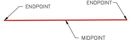
A Line
Base Sketch
The Base sketch is the first 2D sketch drawn in a new part. After the Base sketch is complete, it is extruded or revolved to create the Base model. Before drawing the Base sketch, you should study the model being constructed to determine the best plane to draw it on. The best view to use is the view with the most complex contour shape that does not contain arcs and curves. Draw the lines using lengths close to the finished dimensions. They do not have to be 100% accurate in length. The following rules should be followed when drawing the base sketch.
- The objects in the sketch must meet exactly at their endpoints and cannot overlap.
- The objects must form a perfect closed polygon and cannot contain any gaps.
- The objects must have geometrical constraints applied to control the shape of the sketch.
- Leave fillets and chamfers out of the original sketch. They can be added to the model after it is created. This is taught in Module 15.
X0Y0Z0
The two bold grid lines on the sketching plane represents the X and Y axis of the Cartesian Coordinate System. The axis lines display can be either enabled or disabled. It should currently be enabled. The horizontal line is the X axis and the vertical line is the Y axis. The point where they intersect is X0Y0Z0 of the sketch. Z is always zero since it is a 2D sketch.
The location of X0Y0Z0 on the Base sketch is a very important. You should pick its location on sketch carefully since it dictates the location of X0Y0Z0 on the completed model. See Figure 4-7.
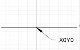
X0Y0 Origin Location
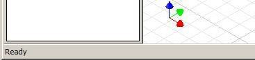
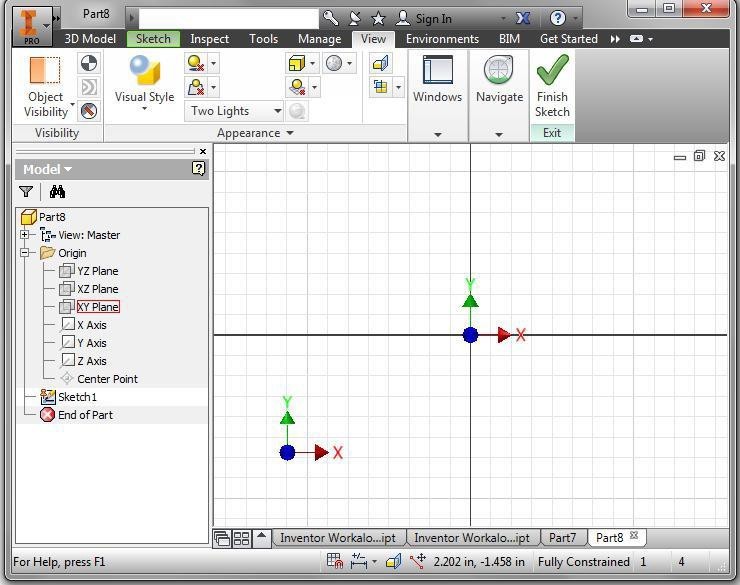
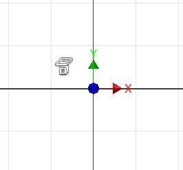
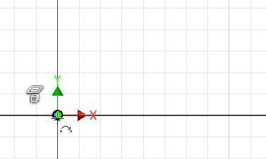
The Coordinate System Indicator shows the X, Y, and Z axis. The arrows always point in the positive X, Y, and Z direction. The red arrow is the X axis , the green arrow is the Y axis, the blue arrow is the z axis. See Figure 4-8 and 4-9.
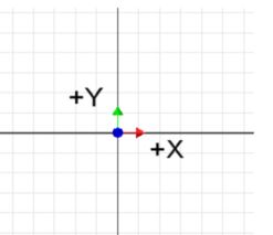
Coordinate System Indicator
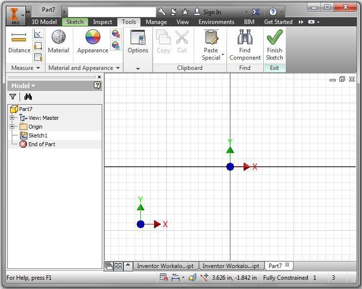
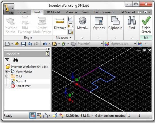
The Graphic window in 2D Sketch Mode [Click to see image full size]
AUTHOR’S COMMENTS: Your Graphic window should appear black as shown in the upper figure below while the Graphic window figures shown in future modules in the Inventor book will have a white background as shown in the lower figure. I used the white background in the book because they displays better.

WORK ALONG: Drawing the Base Sketch
Step 1
Start Inventor. Ensure that the current project is Inventor Course.
Step 2
Click the NEW command and start a new part using the template: English-Modules Part (in).ipt.
Step 3
Change to Model mode by clicking in the Finish sketch icon.
Step 4
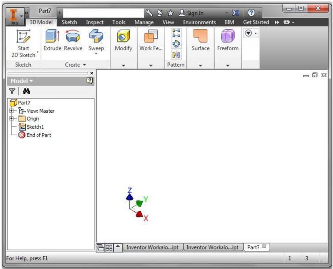
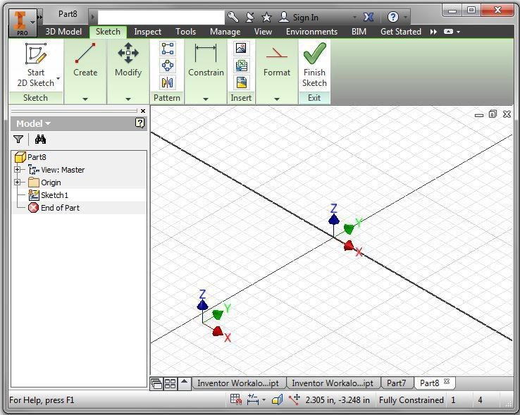
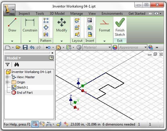
Save the part file with the name: Inventor Workalong 04-1. The Graphic window should appear similar to the figure. (Figure Step 4)
Step 5
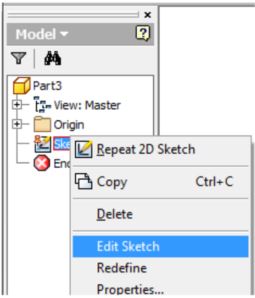
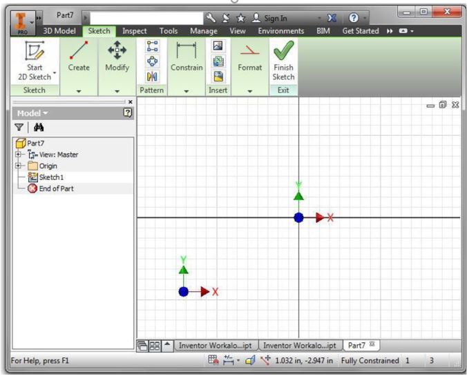
Change to Sketch mode by right clicking Sketch1 in the Browser bar and click Edit Sketch. (Figure Step 5A and 5B)
Step 6
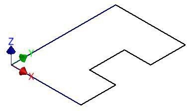
The 3D model that you are constructing in this workalong is shown in the figure. (Figure Step 6A)

Step 7
Press F6 to change to the Home view. (Figure Step 7)
Step 8
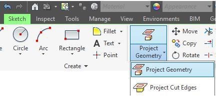
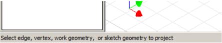
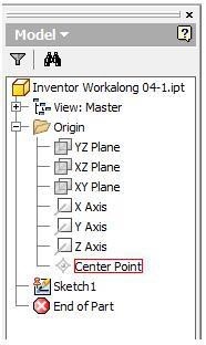
Click the PROJECT GEOMETRY command. Note the Status bar, it displays the command prompt. Expand the Origin folder in the Browser bar and click Center Point. Press Esc to end the command and note that after you do that, the Status bar displays the Ready prompt. That means there is no current command. (Figure Step 8A, 8B, 8C, and 8D)
Step 9
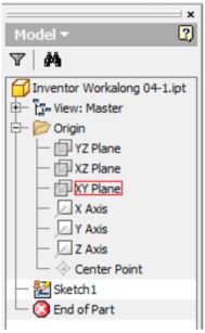
Click the LOOK AT command. Move the cursor onto the Browser bar and click the XY Plane. The Graphic window will change to display the top view. Press Esc to end the command. (Figure Step 9A, 9B, and 9C)
Step 10
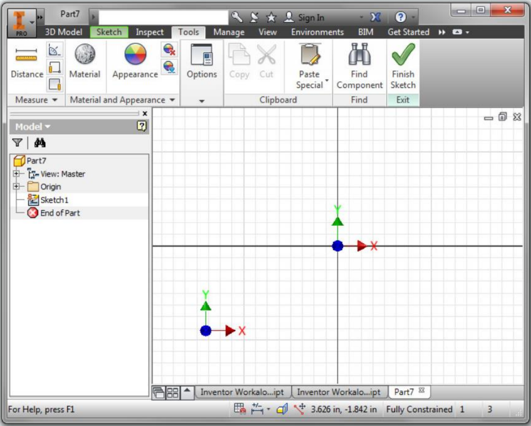
Press F8. It enables the display of the geometrical constraint icons. To this point, there is only one geometrical constraint applied to sketch. It is the Reference constrain that was applied when you projected the Center Point using the PROJECT GEOMETRY command in Step 8. (Figure Step 10)
Step 11
Press F9 to disable the display of the geometrical constraint icons.
Step 12
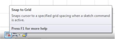
Move the cursor somewhere in the Graphic window and right click the mouse. In the Right-click menu, ensure that Snap to Grid is enabled. (Figure Step 12)
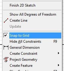
AUTHOR’S COMMENTS: Snap to Grid can be also enabled in the Status bar as shown below.
Step 13
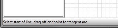
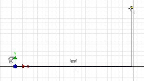
Click the LINE command. Note the Status bar prompt. Move the cursor to X0Y0Z0 and hold it there. A green snap point will display. That means it is snapping to the Center Point geometry that was projected in Step 8. While the green snap point is displayed, click the left mouse button. (Figure Step 13A, 13B, and 13C)
Step 14
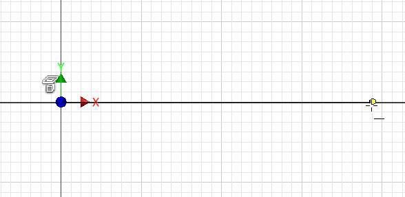
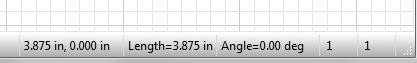
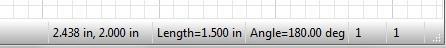
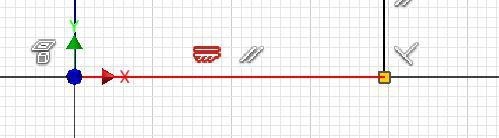
Move the cursor about 4 inches along the positive X axis. Watch the Status bar and it will display the length of the line as the cursor is moved. When it is about 4 inches long and the Horizontal geometrical constraint symbol and the yellow snap point displays, click the left mouse button. (Figure Step 14A and 14B)
Step 15
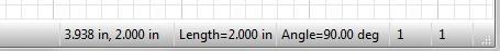
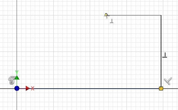
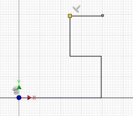
Move the cursor about 2 inches in the positive Y direction. When the Perpendicular geometrical constraint symbol displays at the same time as the yellow grid snap point, click the left mouse button. (Figure Step 15A and 15B)
Step 16
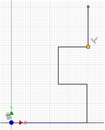
Move the cursor about 2 inches in the negative X direction. When the Perpendicular constraint symbol displays and the yellow snap grid point displays, click the left mouse button. (Figure Step 16A and 16B)
Step 17
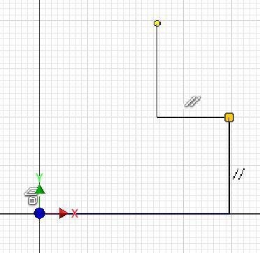
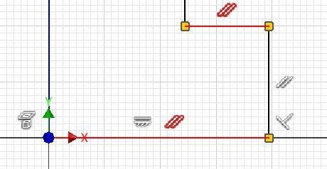
Move the cursor about 2 inches in the positive Y direction. When the Parallel constraint symbol and the yellow snap grid point displays, click the left mouse button. (Figure Step 17A and 17B)

Step 18
Move the cursor about 2 inches in the positive X direction. When the Perpendicular constraint symbol and the yellow snap grid point displays, click the left mouse button. (Figure Step 18A and 18B)

Step 19
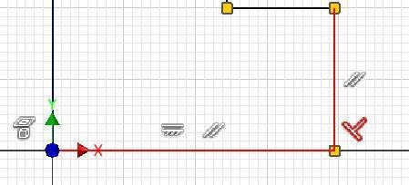
Move the cursor about 2 inches in the positive Y direction. When the Perpendicular constraint symbol and the yellow snap grid point displays, click the left mouse button. (Figure Step 19)
Step 20
Move the cursor about 4 inches in the negative X direction. When the Perpendicular constraint symbol and the yellow snap grid point displays, on the Y axis, click the left mouse button. (Figure Step 20)
Step 21
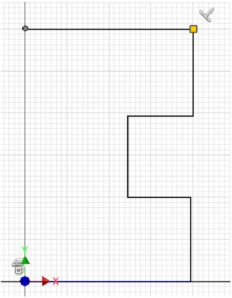
Move the cursor to X0Y0Z0. When the green snap point and the Perpendicular constraint symbol displays, click the left mouse button. (Figure Step 21)
Step 22
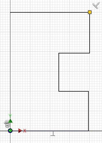
Press Esc to end the LINE command. Note that the Status bar prompts Ready meaning there is no current command. (Figure Step 22)
Step 23
Click the LOOK AT command and change the view to the top or XY plane. If you have trouble, see Step 9.
Step 24
Press F8 to display the geometrical constraint icons. They should appear similar to the figure. (Figure Step 24)
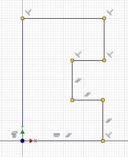
Step 25
Move the cursor onto the Horizontal geometrical constraint icon. Note how the bottom line display red to indicate that the constraint is applied to that line. (Figure Step 25)
Step 26
Move the cursor onto a Parallel geometrical constraint icon and note how another Parallel geometrical constraint icon will highlight showing you which two icons match one another. Note how the two parallel lines will also highlight to indicate that the upper line is constrained to the lower line with a Parallel geometric constraint. (Figure Step 26)
Step 27
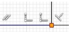
Move the cursor onto the Perpendicular geometrical constraint icon. Note how the two lines highlight. The vertical line is constrained perpendicular to the horizontal line. (Figure Step 27)
Step 28
Move the cursor onto the small square icon at the bottom right corner of the object. Note how two Coincident geometrical constraint icons will display indicating both line’s endpoints are at the exact same XY location. (Figure Step 28)
Step 29
Press F9 to disable the display of the geometrical constraint icons. Press F6 to display the Home view. The completed sketch should appear as shown in the figure. (Figure Step 29)
Step 30
Return to Model mode.
Step 31
Save and close the file.
AUTHOR’S COMMENTS: The final sketch is shown in black as your screen should. Note that two lines are purple and the remainder are blue. If the two lines do not display purple, redo the workalong. You will learn the importance of this in Module 5.
Deleting Lines
There are two methods to delete any unwanted drawing object.
Method 1
Ensure that there is no active command and without entering a command, select the drawing object with the cursor. If it is successfully selected, it will change colour. Right click the mouse. In the Right-click menu, click Delete as shown in Figure 4-9.
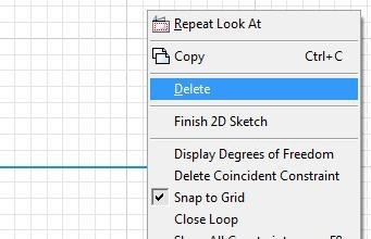
Deleting Lines
Method 2
Select the drawing object the same way as in Method 1. When the selected object changes colour, press the Delete key on the keyboard.
Key Principles
Key Principles in Module 4
- Inventor is a true Three Dimensional Parametric Solid Modeling system. A parametric solid model is a 3 dimensional solid model designed with parameters and constraints rather then hard dimensions.
- Geometrical constraints are used to apply geometrical relationships on or between the objects in the 2D sketch. They specify the geometrical relationship the objects have to the sketching plane or one another.
- It is absolutely imperative that, when required, you snap to grids or pre-defined locations on objects when drawing 2D sketches. Snapping ensures that the sketch is drawn accurately and constrained correctly.
- The Base sketch is the first sketch drawn. The Base sketch is extruded or revolved to create the Base model. Before drawing the Base sketch, you should select the view with the most complex contour shape to draw the sketch on.
- Projected geometry is geometry that has its position fixed relative to the sketching plane where it originates. Drawing objects in the sketch are constrained or dimensioned to the projected geometry to constrain it to the sketching plane.
Lab Exercise 4-1
Time allowed: 40 minutes.
| Part Name | Project | Units | Template | Color | Material |
| Inventor Lab 04-1 | Inventor Course | Inches | English-Modules Part (in).ipt | N/A | N/A |
Step 1
Start a new part file with the template: English – Modules Part(in).ipt save the file with the name: Inventor Lab 04-1 as shown above.
Step 2
Project the Center Point onto the Base sketch.
Step 3
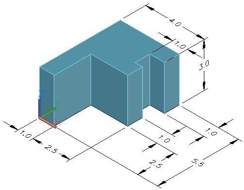
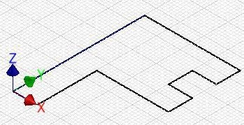
Draw the Base sketch for the 3D model shown below and apply all of the necessary geometrical constraints. Note the location of X0Y0Z0. (Figure Step 3A and 3B)
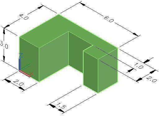
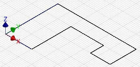
Base Sketch
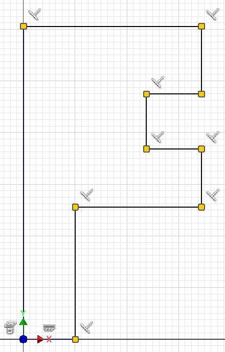
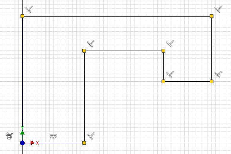
AUTHOR’S GEOMETRIC CONSTRAINS: The following figure shows the Base sketch’s geometric constraints suggested by the author to help you learn how to construct and constrain sketches. It is only the suggested method and if you can complete a fully constrained sketch using different construction methods and constraints, that is what is important. You may want to compare your construction method and constraints used with the authors.
Lab Exercise 4-2
Time allowed: 40 minutes.
| Part Name | Project | Units | Template | Color | Material |
| Inventor Lab 04-2 | Inventor Course | Inches | English-Modules Part (in).ipt | N/A | N/A |
Step 1
Start a new part file with the template: English – Modules Part(in).ipt and save the file with the name: Inventor Lab 04-2 as shown above.
Step 2
Project the Center Point onto the Base sketch.
Step 3
Draw the Base sketch for the 3D model shown below and apply all of the necessary geometrical constraints. Note the location of X0Y0Z0. (Figure Step 3A and 3B)
AUTHOR’S GEOMETRIC CONSTRAINS: The following figure shows the Base sketch’s geometric constraints suggested by the author to help you learn how to construct and constrain sketches. It is only the suggested method and if you can complete a fully constrained sketch using different construction methods and constraints, that is what is important. You may want to compare your construction method and constraints used with the authors.