
3.1: Module 12 Circles
- Page ID
- 19876

\( \newcommand{\vecs}[1]{\overset { \scriptstyle \rightharpoonup} {\mathbf{#1}} } \)
\( \newcommand{\vecd}[1]{\overset{-\!-\!\rightharpoonup}{\vphantom{a}\smash {#1}}} \)
\( \newcommand{\id}{\mathrm{id}}\) \( \newcommand{\Span}{\mathrm{span}}\)
( \newcommand{\kernel}{\mathrm{null}\,}\) \( \newcommand{\range}{\mathrm{range}\,}\)
\( \newcommand{\RealPart}{\mathrm{Re}}\) \( \newcommand{\ImaginaryPart}{\mathrm{Im}}\)
\( \newcommand{\Argument}{\mathrm{Arg}}\) \( \newcommand{\norm}[1]{\| #1 \|}\)
\( \newcommand{\inner}[2]{\langle #1, #2 \rangle}\)
\( \newcommand{\Span}{\mathrm{span}}\)
\( \newcommand{\id}{\mathrm{id}}\)
\( \newcommand{\Span}{\mathrm{span}}\)
\( \newcommand{\kernel}{\mathrm{null}\,}\)
\( \newcommand{\range}{\mathrm{range}\,}\)
\( \newcommand{\RealPart}{\mathrm{Re}}\)
\( \newcommand{\ImaginaryPart}{\mathrm{Im}}\)
\( \newcommand{\Argument}{\mathrm{Arg}}\)
\( \newcommand{\norm}[1]{\| #1 \|}\)
\( \newcommand{\inner}[2]{\langle #1, #2 \rangle}\)
\( \newcommand{\Span}{\mathrm{span}}\) \( \newcommand{\AA}{\unicode[.8,0]{x212B}}\)
\( \newcommand{\vectorA}[1]{\vec{#1}} % arrow\)
\( \newcommand{\vectorAt}[1]{\vec{\text{#1}}} % arrow\)
\( \newcommand{\vectorB}[1]{\overset { \scriptstyle \rightharpoonup} {\mathbf{#1}} } \)
\( \newcommand{\vectorC}[1]{\textbf{#1}} \)
\( \newcommand{\vectorD}[1]{\overrightarrow{#1}} \)
\( \newcommand{\vectorDt}[1]{\overrightarrow{\text{#1}}} \)
\( \newcommand{\vectE}[1]{\overset{-\!-\!\rightharpoonup}{\vphantom{a}\smash{\mathbf {#1}}}} \)
\( \newcommand{\vecs}[1]{\overset { \scriptstyle \rightharpoonup} {\mathbf{#1}} } \)
\( \newcommand{\vecd}[1]{\overset{-\!-\!\rightharpoonup}{\vphantom{a}\smash {#1}}} \)
\(\newcommand{\avec}{\mathbf a}\) \(\newcommand{\bvec}{\mathbf b}\) \(\newcommand{\cvec}{\mathbf c}\) \(\newcommand{\dvec}{\mathbf d}\) \(\newcommand{\dtil}{\widetilde{\mathbf d}}\) \(\newcommand{\evec}{\mathbf e}\) \(\newcommand{\fvec}{\mathbf f}\) \(\newcommand{\nvec}{\mathbf n}\) \(\newcommand{\pvec}{\mathbf p}\) \(\newcommand{\qvec}{\mathbf q}\) \(\newcommand{\svec}{\mathbf s}\) \(\newcommand{\tvec}{\mathbf t}\) \(\newcommand{\uvec}{\mathbf u}\) \(\newcommand{\vvec}{\mathbf v}\) \(\newcommand{\wvec}{\mathbf w}\) \(\newcommand{\xvec}{\mathbf x}\) \(\newcommand{\yvec}{\mathbf y}\) \(\newcommand{\zvec}{\mathbf z}\) \(\newcommand{\rvec}{\mathbf r}\) \(\newcommand{\mvec}{\mathbf m}\) \(\newcommand{\zerovec}{\mathbf 0}\) \(\newcommand{\onevec}{\mathbf 1}\) \(\newcommand{\real}{\mathbb R}\) \(\newcommand{\twovec}[2]{\left[\begin{array}{r}#1 \\ #2 \end{array}\right]}\) \(\newcommand{\ctwovec}[2]{\left[\begin{array}{c}#1 \\ #2 \end{array}\right]}\) \(\newcommand{\threevec}[3]{\left[\begin{array}{r}#1 \\ #2 \\ #3 \end{array}\right]}\) \(\newcommand{\cthreevec}[3]{\left[\begin{array}{c}#1 \\ #2 \\ #3 \end{array}\right]}\) \(\newcommand{\fourvec}[4]{\left[\begin{array}{r}#1 \\ #2 \\ #3 \\ #4 \end{array}\right]}\) \(\newcommand{\cfourvec}[4]{\left[\begin{array}{c}#1 \\ #2 \\ #3 \\ #4 \end{array}\right]}\) \(\newcommand{\fivevec}[5]{\left[\begin{array}{r}#1 \\ #2 \\ #3 \\ #4 \\ #5 \\ \end{array}\right]}\) \(\newcommand{\cfivevec}[5]{\left[\begin{array}{c}#1 \\ #2 \\ #3 \\ #4 \\ #5 \\ \end{array}\right]}\) \(\newcommand{\mattwo}[4]{\left[\begin{array}{rr}#1 \amp #2 \\ #3 \amp #4 \\ \end{array}\right]}\) \(\newcommand{\laspan}[1]{\text{Span}\{#1\}}\) \(\newcommand{\bcal}{\cal B}\) \(\newcommand{\ccal}{\cal C}\) \(\newcommand{\scal}{\cal S}\) \(\newcommand{\wcal}{\cal W}\) \(\newcommand{\ecal}{\cal E}\) \(\newcommand{\coords}[2]{\left\{#1\right\}_{#2}}\) \(\newcommand{\gray}[1]{\color{gray}{#1}}\) \(\newcommand{\lgray}[1]{\color{lightgray}{#1}}\) \(\newcommand{\rank}{\operatorname{rank}}\) \(\newcommand{\row}{\text{Row}}\) \(\newcommand{\col}{\text{Col}}\) \(\renewcommand{\row}{\text{Row}}\) \(\newcommand{\nul}{\text{Nul}}\) \(\newcommand{\var}{\text{Var}}\) \(\newcommand{\corr}{\text{corr}}\) \(\newcommand{\len}[1]{\left|#1\right|}\) \(\newcommand{\bbar}{\overline{\bvec}}\) \(\newcommand{\bhat}{\widehat{\bvec}}\) \(\newcommand{\bperp}{\bvec^\perp}\) \(\newcommand{\xhat}{\widehat{\xvec}}\) \(\newcommand{\vhat}{\widehat{\vvec}}\) \(\newcommand{\uhat}{\widehat{\uvec}}\) \(\newcommand{\what}{\widehat{\wvec}}\) \(\newcommand{\Sighat}{\widehat{\Sigma}}\) \(\newcommand{\lt}{<}\) \(\newcommand{\gt}{>}\) \(\newcommand{\amp}{&}\) \(\definecolor{fillinmathshade}{gray}{0.9}\)12
Module 12 Circles
Wally Baumback
Learning Outcomes
When you have completed this module, you will be able to:
- Describe construction objects and their use in a 2D sketch.
- Describe drawing circles and offsets in a 2D sketch.
- Apply the CENTER POINT CIRCLE and OFFSET commands to complete 2D sketches.
Geometry Lesson: Circles
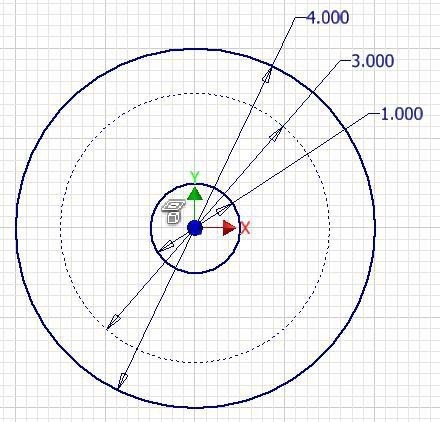
A circle is defined as a closed curve in which all points are the same distance from its centre point. The centre point is a single XY coordinate. A circle is 360 degrees and can be divided into four quadrants. All points on a circle are at a given distance from is centre point. The distance between any of the points and the centre is called the radius.
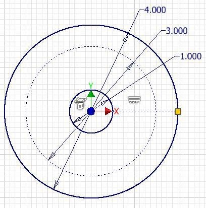
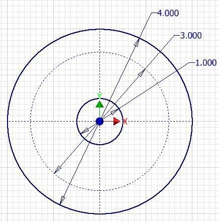
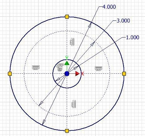
Study the drawings in Figure 12-1, 12-2, 12-3, and 12-4 for a description of the geometry of a circle.
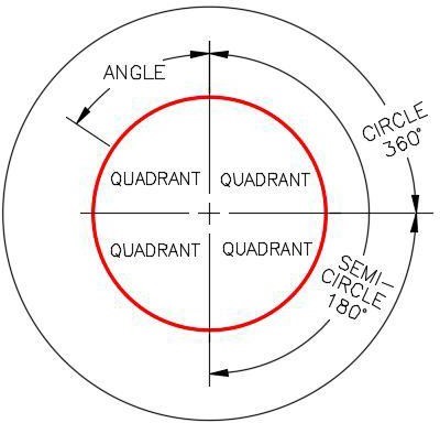
Geometry of a Circle – Part 1 [Click to see image full size]
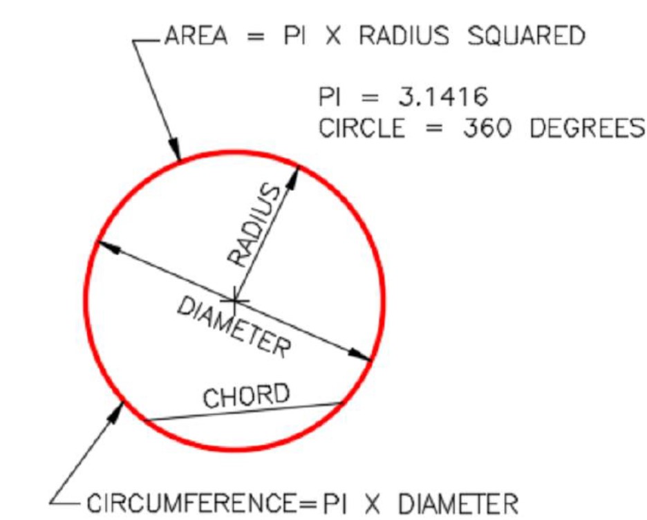
Geometry of a Circle – Part 2 [Click to see image full size]
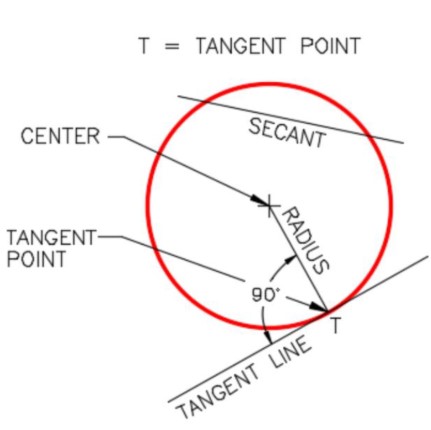
Geometry of a Circle – Part 3 [Click to see image full size]
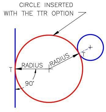
Geometry of a Circle – Part 4
Drafting Lesson: Reading Dimensions for Circles and Arcs
When reading the dimensions for circles and arcs, consider the following: Circles are dimensioned as diameters. For example: 2.0 DIA.
Arcs are dimensioned as radii. For example: 1.5 R
When there is more than one circle of the same diameter, they are only dimensioned once. For example: 0.5 DIA., 4 PLACES
Sometimes multiple arcs are dimensioned as typical (TYP.). For example: 2.0 R TYP. This simply means that there is at least one additional arc of the same size, See Figure 12-5.
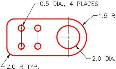
Typical Drawing
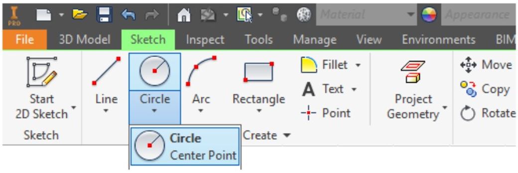
Inventor Command: CENTER POINT CIRCLE
The CENTER POINT CIRCLE command is used to draw a circle by entering the location of its centre point and its radius.
Shortcut: C
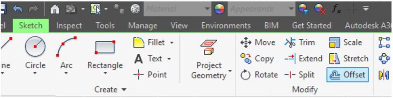
Inventor Command: OFFSET
The OFFSET command is used to draw an object parallel to an existing object.
Shortcut: O
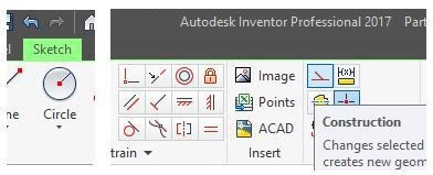
Construction objects are objects that are drawn in the sketch to assist you to complete the sketch but will be ignored by Inventor when the sketch is extruded or revolved to create the Base model. Geometrical and dimensional constraints can be applied to construction objects the same as they are to drawing objects. Construction objects and drawing objects only differ in the properties of the objects. They are both drawn and manipulated the same way in a 2D sketch.
There are two methods of creating construction objects as follows:
Method 1
Enable the Construction icon, see Figure 12-6, and then draw the objects. All objects drawn while the Construction icon is enabled, will be created as construction objects.
Method 2
Draw the object with the Construction icon disabled. After the drawing object(s) is created, select it. While it is selected, click the Construction icon. Construction objects will appear as a dashed lines as shown in Figure 12-7.
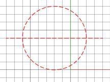
Construction Objects
WORK ALONG: Drawing Circles and Cylindrical Models
Step 1
Check the default project and if necessary, set it to Inventor Course.
Step 2
Enter the NEW command to start a new part file using the template: English-Modules Part (in).ipt.
Step 3
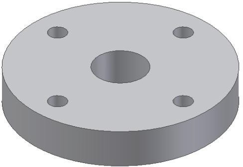
Save the file with the name: Inventor Workalong 12-1. (Figure Step 3A and 3B)
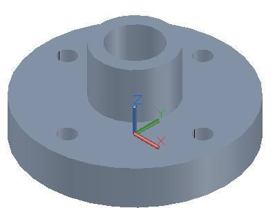
3D Model
Home View [Click to see image full size]
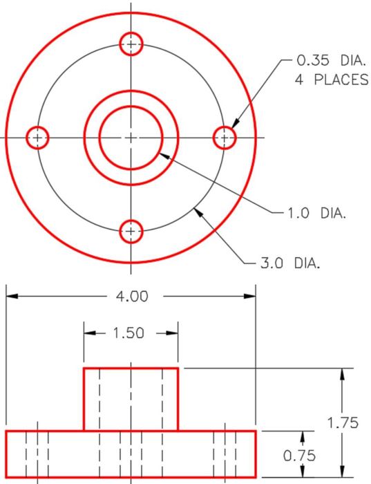
Dimensioned Multiview Drawing [Click to see image full size]
Step 4
Draw the Base sketch on the Top view. Since this is the XY plane (the default plane), use Sketch1.
Step 5
Project the Center Point onto the sketching plane.
Step 6
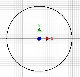
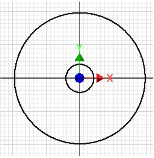
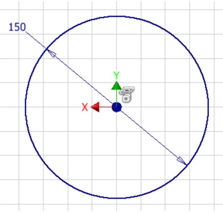
Enter the CENTER POINT CIRCLE command and draw a 4.0 inch diameter circle. Watch the Status bar. The first prompt will be to select the centre point for the circle. For the centre point location, snap to the Center Point that was projected onto the sketching plane. Select the radius by guessing 2 inches from the centre. (Figure Step 6)
Step 7
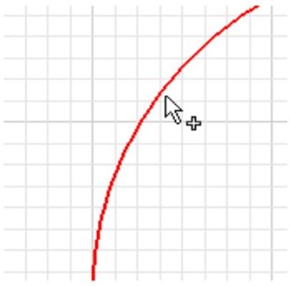
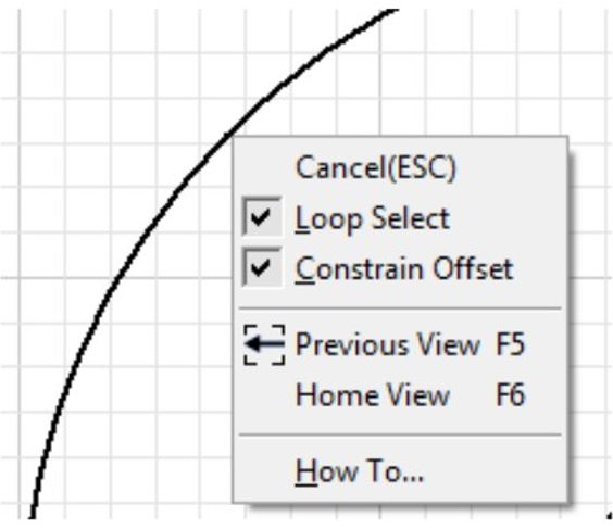
Click the OFFSET command and when prompted, select the circle. Right-click the mouse. In the Right-click menu, ensure that Loop Select is enabled. Move the mouse towards the centre, guess at the diameter size of the 1.0 inch. (Figure Step 7A, 7B, and 7C)
Step 8
Click the Construction icon to enable it. (Figure Step 8)

Step 9
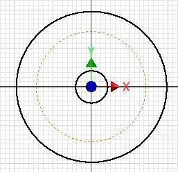
Using what you just learned, enter the OFFSET command and offset the large circle to draw the 3 inch diameter construction circle. (Figure Step 9)
Step 10
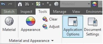
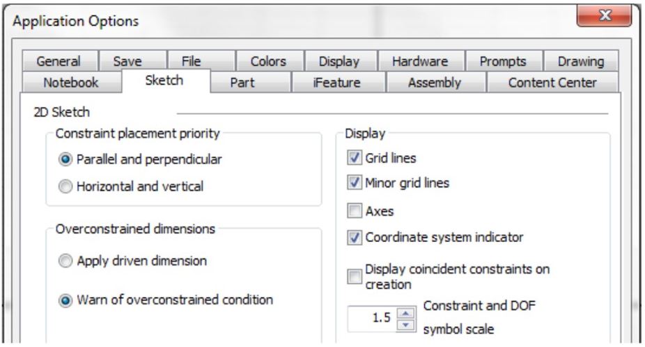
Click the Tools menu. Click the Applications Options icon to open the Applications Options dialogue box. Enable the Sketch tab. In the Display area, disable Axes. Click OK to close the dialogue box. (Figure Step 10A and 10B)
Step 11
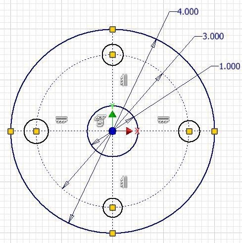
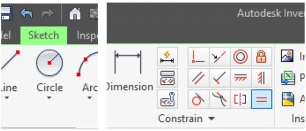
Dimension the three circles. Press F8 to display the geometrical constraint icons. (Figure Step 11)
Step 12
Using the LINE command, draw a line by first snapping to the Center Point and ending it by snapping onto the circle. Make sure that the Horizontal constraint icon displays when you are drawing the line. The constraint icons should appear similar to the figure. (Figure Step 12)
Step 13
Using the LINE command, draw three additional construction lines by first snapping to the Center Point and ending them by snapping onto the circle. The constraint icons should appear similar to the figure. (Figure Step 13)
Step 14
Press F8 to display the constraint icons. (Figure Step 14)
Step 15
Click the Construction icon to disable it.
Step 16
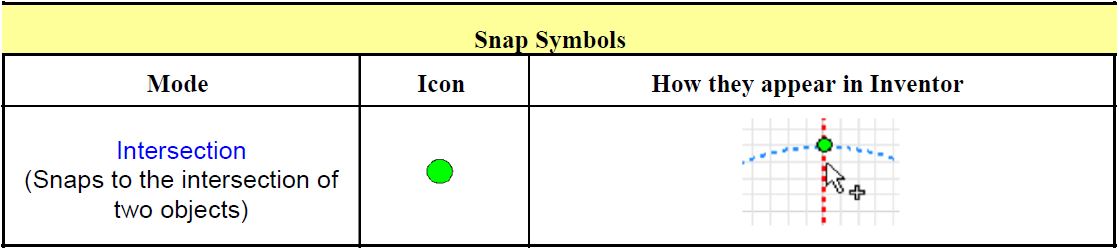
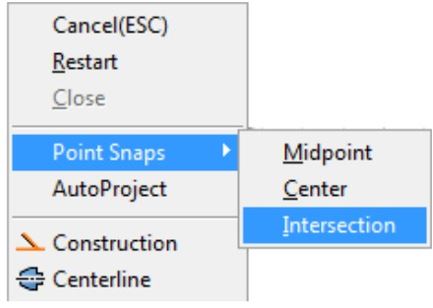
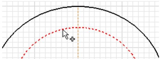
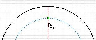
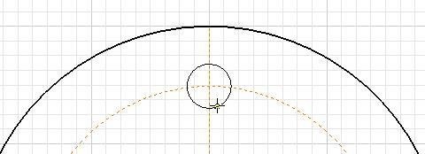
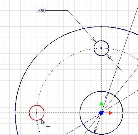
Enter the CENTER POINT CIRCLE command. With the cursor in the sketching window, right-click the mouse. In the Right-click menu, select Intersection. Select the construction circle and then the construction line. Notice how the cursor will display a plus sign beside it. When you select the line, the green snap indicator will display. Select a location for the radius of the circle by guessing at its size. (Figure Step 16A, 16B, 16C, and 16D)
Step 17
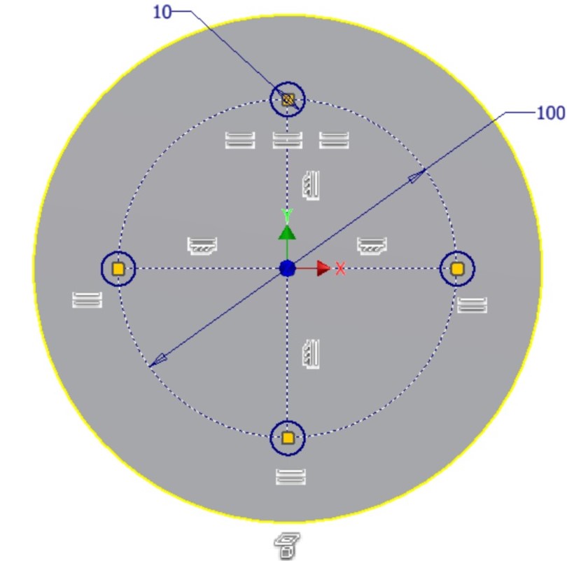
Using what you just learned in Step 14, insert the 3 additional circles. For now, the diameter of the circles is not important. (Figure Step 17)
Step 18
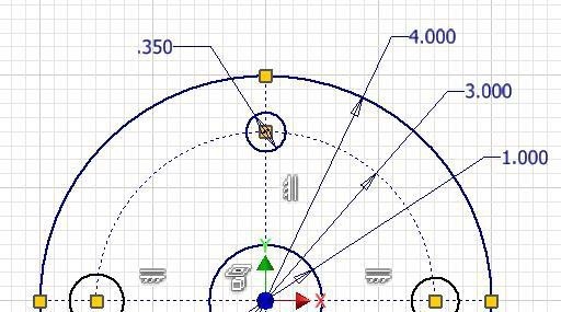
Dimension one circle only. (Figure Step 18)
Step 19
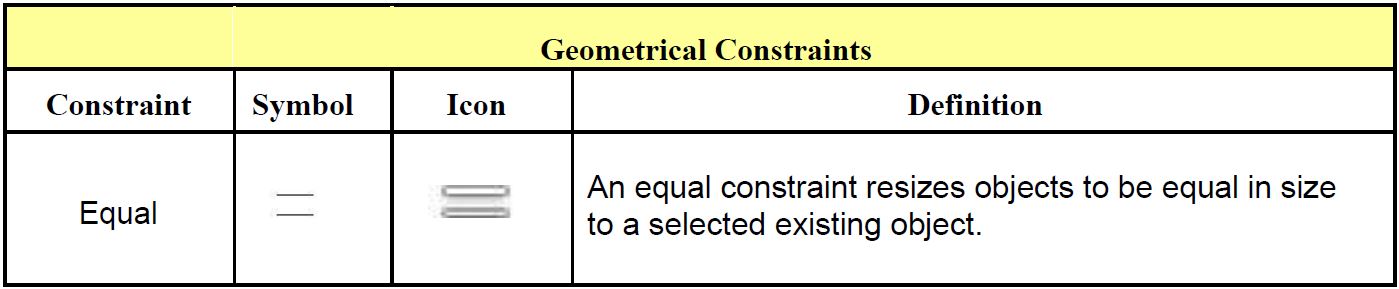
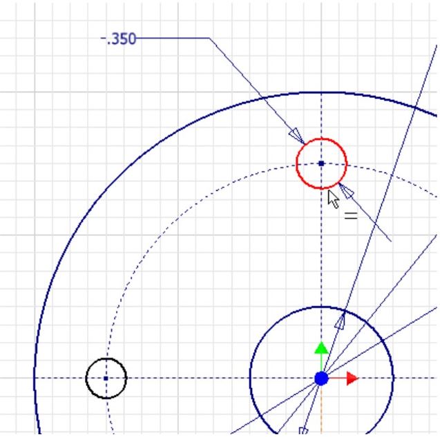
Ensure that there is no active command and select the Equal constrain icon. (Figure Step 19)
Step 20
For the first circle, select the top (dimensioned circle) and for the second circle select one of the other circles. It will constrain the second circle as equal in size to the dimensioned circle. (Figure Step 20A and 20B)
Step 21
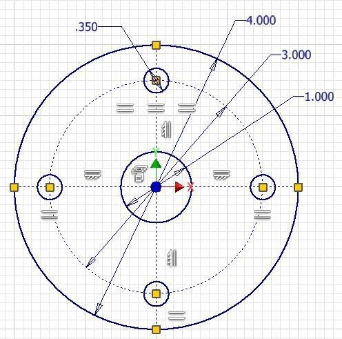
Using what you learned in Step 20, constrain the additional 2 circles with the Equal constraint to equal the dimensioned circle. The constraint icons should appear similar to the figure. (Figure Step 21)
Step 22
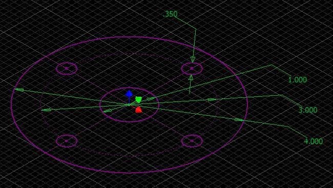
Change the view to the Home view. The sketch should be fully constrained and display purple. (Figure Step 22)
Step 23
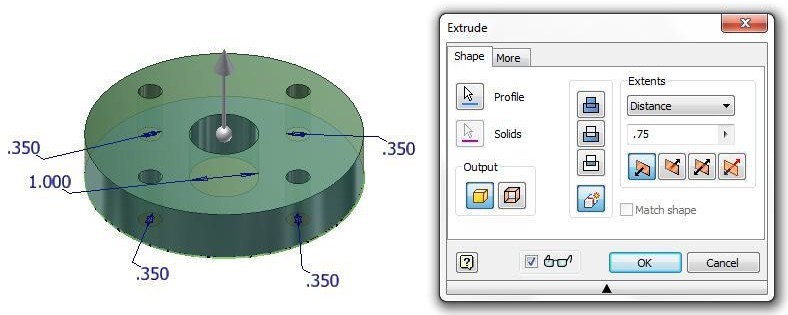
Extrude the sketch as shown in the figure. (Figure Step 23A and 23B)
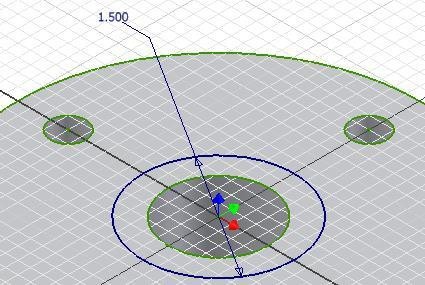
Step 24
Start a new sketch on the top plane of the model. Using the OFFSET command, offset the outside diameter of the object to insert a 1.5 inch circle. Add the diameter dimension as shown in figure. (Figure Step 24)
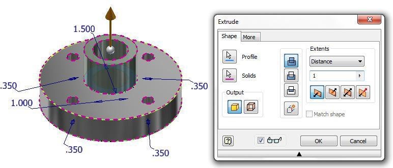
Step 25
Extrude the sketch as shown in figure. (Figure Step 25)
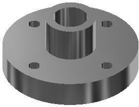
Step 26
Change the colour to: Chrome -Polished Black. (Figure Step 26)
Step 27
Save and close the file.
Key Principles
Key Principles in Module 12
- Construction objects are objects that are drawn in the sketch to assist you in completing the sketch but will be ignored by Inventor when the sketch is extruded or revolved. Geometrical and dimensional constraints can be applied to construction objects the same as they are to drawing Construction objects and drawing objects only differ in the properties of the objects. They are both drawn and manipulated the same way in a 2D sketch.
- To select more then one object at time, hold down either the CTRL or SHIFT key while selecting the objects.
Lab Exercise 12-1
Time allowed: 45 minutes.
| Part Name | Project | Units | Template | Color | Material |
| Inventor Lab Lab 12-1 | Inventor Course | Millimeters | Metric-Modules Part (mm).ipt | Aluminum – Flat | N/A |
Step 1
Project the Center Point onto the Base plane.
Step 2
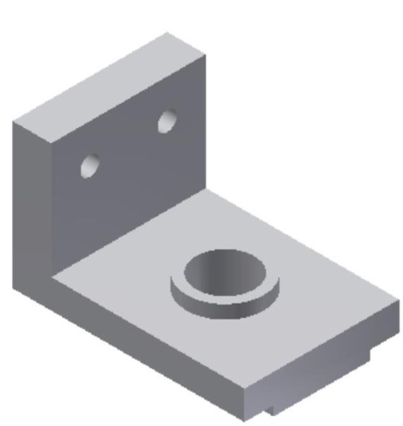
Note the location of X0Y0Z0. Draw the necessary sketches and extrude them to produced the solid model shown below. Apply all of the necessary geometrical and dimensional constraints to fully constrain all sketches. (Figure Step 2A and 2B)
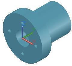
Solid Model – Home View
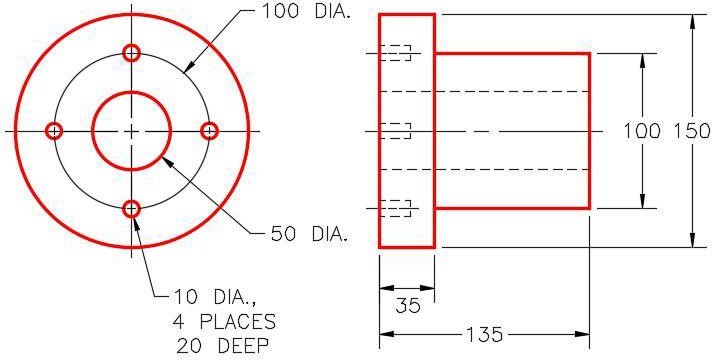
Dimensioned Multiview Drawing [Click to see image full size]
Step 3
Apply the colour shown above. (Figure Step 3A and 3B)
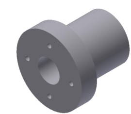
Solid Model – Home View
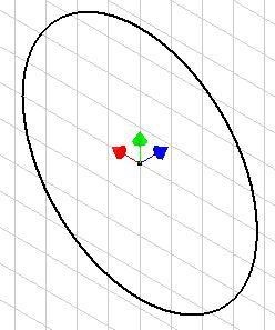
Suggested Base Sketch –
Front – XZ Plane
Hint:
The small holes do NOT go all the way through the flange.
AUTHOR’S GEOMETRIC CONSTRAINTS: The following figures shows the sketch’s construction method plus geometric and dimensional constraints suggested by the author to help you learn how to construct and constrain sketches. It is only the suggested method and if you can complete a fully constrained sketch using a different construction method and constraints, that is what is important. You may want to compare your construction method and constraints with the authors.
Lab Exercise 12-2
Time allowed: 45 minutes.
| Part Name | Project | Units | Template | Color | Material |
| Inventor Lab Lab 12-2 | Inventor Course | Inches | English-Modules Part (in).ipt | White | N/A |
Step 1
Project the Center Point onto the base plane.
Step 2
Note the location of X0Y0Z0. Draw the necessary sketches and extrude them to produced the solid model shown below. Apply all of the necessary geometrical and dimensional constraints to fully constrain all sketches. (Figure Step 2A and 2B)
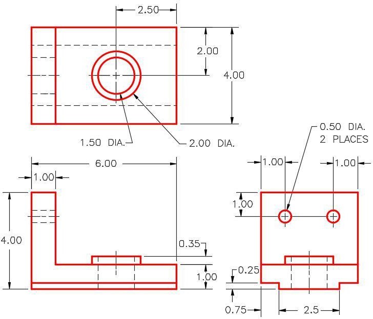
Dimensioned Multiview Drawing [Click to see image full size]
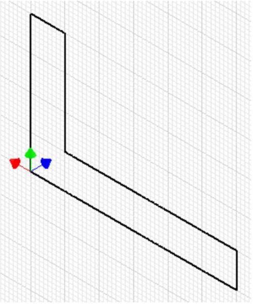
Suggested Base Sketch –
Front – XZ Plane [Click to see image full size]
Hint
Draw the base sketch on the Front view or XZ plane.
Step 3
Apply the colour shown above. (Figure Step 3A and 3B)
Completed Solid Model – Home View [Click to see image full size]
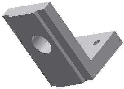
Completed Solid Model – Bottom View [Click to see image full size]