4.1: Module 17 Angles
- Page ID
- 19882

\( \newcommand{\vecs}[1]{\overset { \scriptstyle \rightharpoonup} {\mathbf{#1}} } \)
\( \newcommand{\vecd}[1]{\overset{-\!-\!\rightharpoonup}{\vphantom{a}\smash {#1}}} \)
\( \newcommand{\id}{\mathrm{id}}\) \( \newcommand{\Span}{\mathrm{span}}\)
( \newcommand{\kernel}{\mathrm{null}\,}\) \( \newcommand{\range}{\mathrm{range}\,}\)
\( \newcommand{\RealPart}{\mathrm{Re}}\) \( \newcommand{\ImaginaryPart}{\mathrm{Im}}\)
\( \newcommand{\Argument}{\mathrm{Arg}}\) \( \newcommand{\norm}[1]{\| #1 \|}\)
\( \newcommand{\inner}[2]{\langle #1, #2 \rangle}\)
\( \newcommand{\Span}{\mathrm{span}}\)
\( \newcommand{\id}{\mathrm{id}}\)
\( \newcommand{\Span}{\mathrm{span}}\)
\( \newcommand{\kernel}{\mathrm{null}\,}\)
\( \newcommand{\range}{\mathrm{range}\,}\)
\( \newcommand{\RealPart}{\mathrm{Re}}\)
\( \newcommand{\ImaginaryPart}{\mathrm{Im}}\)
\( \newcommand{\Argument}{\mathrm{Arg}}\)
\( \newcommand{\norm}[1]{\| #1 \|}\)
\( \newcommand{\inner}[2]{\langle #1, #2 \rangle}\)
\( \newcommand{\Span}{\mathrm{span}}\) \( \newcommand{\AA}{\unicode[.8,0]{x212B}}\)
\( \newcommand{\vectorA}[1]{\vec{#1}} % arrow\)
\( \newcommand{\vectorAt}[1]{\vec{\text{#1}}} % arrow\)
\( \newcommand{\vectorB}[1]{\overset { \scriptstyle \rightharpoonup} {\mathbf{#1}} } \)
\( \newcommand{\vectorC}[1]{\textbf{#1}} \)
\( \newcommand{\vectorD}[1]{\overrightarrow{#1}} \)
\( \newcommand{\vectorDt}[1]{\overrightarrow{\text{#1}}} \)
\( \newcommand{\vectE}[1]{\overset{-\!-\!\rightharpoonup}{\vphantom{a}\smash{\mathbf {#1}}}} \)
\( \newcommand{\vecs}[1]{\overset { \scriptstyle \rightharpoonup} {\mathbf{#1}} } \)
\( \newcommand{\vecd}[1]{\overset{-\!-\!\rightharpoonup}{\vphantom{a}\smash {#1}}} \)
\(\newcommand{\avec}{\mathbf a}\) \(\newcommand{\bvec}{\mathbf b}\) \(\newcommand{\cvec}{\mathbf c}\) \(\newcommand{\dvec}{\mathbf d}\) \(\newcommand{\dtil}{\widetilde{\mathbf d}}\) \(\newcommand{\evec}{\mathbf e}\) \(\newcommand{\fvec}{\mathbf f}\) \(\newcommand{\nvec}{\mathbf n}\) \(\newcommand{\pvec}{\mathbf p}\) \(\newcommand{\qvec}{\mathbf q}\) \(\newcommand{\svec}{\mathbf s}\) \(\newcommand{\tvec}{\mathbf t}\) \(\newcommand{\uvec}{\mathbf u}\) \(\newcommand{\vvec}{\mathbf v}\) \(\newcommand{\wvec}{\mathbf w}\) \(\newcommand{\xvec}{\mathbf x}\) \(\newcommand{\yvec}{\mathbf y}\) \(\newcommand{\zvec}{\mathbf z}\) \(\newcommand{\rvec}{\mathbf r}\) \(\newcommand{\mvec}{\mathbf m}\) \(\newcommand{\zerovec}{\mathbf 0}\) \(\newcommand{\onevec}{\mathbf 1}\) \(\newcommand{\real}{\mathbb R}\) \(\newcommand{\twovec}[2]{\left[\begin{array}{r}#1 \\ #2 \end{array}\right]}\) \(\newcommand{\ctwovec}[2]{\left[\begin{array}{c}#1 \\ #2 \end{array}\right]}\) \(\newcommand{\threevec}[3]{\left[\begin{array}{r}#1 \\ #2 \\ #3 \end{array}\right]}\) \(\newcommand{\cthreevec}[3]{\left[\begin{array}{c}#1 \\ #2 \\ #3 \end{array}\right]}\) \(\newcommand{\fourvec}[4]{\left[\begin{array}{r}#1 \\ #2 \\ #3 \\ #4 \end{array}\right]}\) \(\newcommand{\cfourvec}[4]{\left[\begin{array}{c}#1 \\ #2 \\ #3 \\ #4 \end{array}\right]}\) \(\newcommand{\fivevec}[5]{\left[\begin{array}{r}#1 \\ #2 \\ #3 \\ #4 \\ #5 \\ \end{array}\right]}\) \(\newcommand{\cfivevec}[5]{\left[\begin{array}{c}#1 \\ #2 \\ #3 \\ #4 \\ #5 \\ \end{array}\right]}\) \(\newcommand{\mattwo}[4]{\left[\begin{array}{rr}#1 \amp #2 \\ #3 \amp #4 \\ \end{array}\right]}\) \(\newcommand{\laspan}[1]{\text{Span}\{#1\}}\) \(\newcommand{\bcal}{\cal B}\) \(\newcommand{\ccal}{\cal C}\) \(\newcommand{\scal}{\cal S}\) \(\newcommand{\wcal}{\cal W}\) \(\newcommand{\ecal}{\cal E}\) \(\newcommand{\coords}[2]{\left\{#1\right\}_{#2}}\) \(\newcommand{\gray}[1]{\color{gray}{#1}}\) \(\newcommand{\lgray}[1]{\color{lightgray}{#1}}\) \(\newcommand{\rank}{\operatorname{rank}}\) \(\newcommand{\row}{\text{Row}}\) \(\newcommand{\col}{\text{Col}}\) \(\renewcommand{\row}{\text{Row}}\) \(\newcommand{\nul}{\text{Nul}}\) \(\newcommand{\var}{\text{Var}}\) \(\newcommand{\corr}{\text{corr}}\) \(\newcommand{\len}[1]{\left|#1\right|}\) \(\newcommand{\bbar}{\overline{\bvec}}\) \(\newcommand{\bhat}{\widehat{\bvec}}\) \(\newcommand{\bperp}{\bvec^\perp}\) \(\newcommand{\xhat}{\widehat{\xvec}}\) \(\newcommand{\vhat}{\widehat{\vvec}}\) \(\newcommand{\uhat}{\widehat{\uvec}}\) \(\newcommand{\what}{\widehat{\wvec}}\) \(\newcommand{\Sighat}{\widehat{\Sigma}}\) \(\newcommand{\lt}{<}\) \(\newcommand{\gt}{>}\) \(\newcommand{\amp}{&}\) \(\definecolor{fillinmathshade}{gray}{0.9}\)17
Module 17 Angles
Wally Baumback
Learning Outcomes
When you have completed this module, you will be able to:
- Describe drawing inclined lines, aligned and angular dimensions, loops, trimming, and extending.
- Apply the GENERAL DIMENSIONS command to insert aligned and angular dimensions on a sketch.
- Apply the TRIM and EXTEND commands to trim and extend objects in a sketch.
Drafting Lesson: Auxiliary Views
When a model has an inclined side, its plane is not parallel to the horizontal and vertical sides of the glass box. If the inclined view is drawn in one of the predefined views in a multiview drawing, some or all parts of the object will not be their true size and shape. To correct this, an auxiliary view is drawn instead of a predefined view. An auxiliary view is a view looking perpendicular to the inclined plane as shown in Figure 17-1.
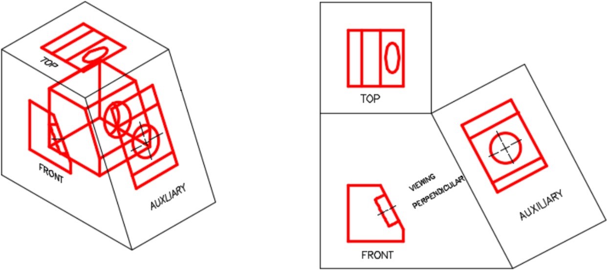
An Auxiliary View [Click to see image full size]
Drafting Lesson: Broken Views and Break Lines
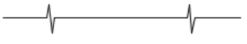
To simplify or speed up drawing some of the views of a multiview drawing are only partially drawn. In these cases, the cutoff (sometimes called the broken) portion of the view is not required for the reader to visualize the object. Auxiliary views are frequently cutoff. When a view is cutoff, a break line is drawn to indicate where the view was broken as shown in Figure 17-2. A short break line and a long break line are drawn differently as show in Figure 17-2.
Broken Views and Break Lines
Inventor Command: TRIM
The TRIM command is used to trim a portion of an existing line or arc. The object to be trimmed must intersect an existing object. If it does not intersect an object, the complete object will be deleted instead of being trimmed.
Shortcut: X
Inventor Command: EXTEND
The TRIM command is used to trim a portion of an existing line or arc. The object to be trimmed must intersect an existing object. If it does not intersect an object, the complete object will be deleted instead of being trimmed.
Shortcut: X
Drawing and Dimensioning Inclined Lines
Drawing and dimensioning inclined lines in sketches is a simple operation in Inventor compared to most CAD systems. The reason for this is that you can guess at the angle when drawing the inclined line rather then entering the exact number of degrees. After the sketch is complete, the angle is dimensioned using the exact angle and Inventor will adjust the sketch to match.
Aligned Dimensions
An aligned dimension is a dimension measuring the true length of a line or the true distance between two points. See Figure 17-3. The extension lines will be perpendicular and the dimension line will be parallel to the line or an imaginary line between two points.
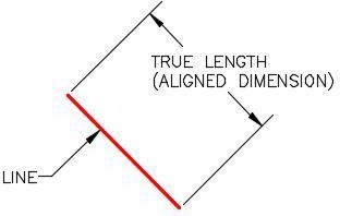
An Aligned Dimension
Placing an Aligned Dimension
To place an aligned dimension, enter the GENERAL DIMENSION command or the shortcut D and regardless if you are selecting a line, two points, or two lines to dimension, the same Aligned dimension icon will display as shown in Figures 17-4 and Figure 17-5.
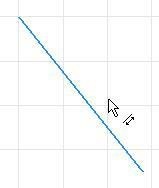
Placing a Aligned
Dimension

Aligned
Dimension Icon
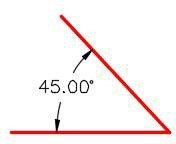
Angular Dimensions
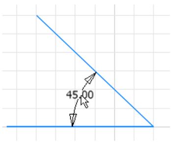
An angular dimension is a dimension measuring the angle between two lines or the angle between the imaginary lines between three points. See Figure 17-6. The lines cannot be parallel to each other.
Placing an Angular Dimension
To place an angular dimension, enter the GENERAL DIMENSION command or the shortcut D and either select two lines or three points to place the angular dimension between.
The Two-Line Method
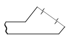
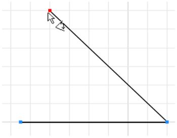
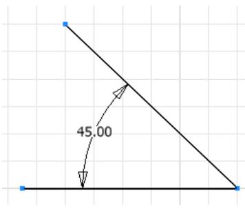
Select the first line. It will change colour. Move the cursor onto the second line and without selecting it, note how it changes colour. The Angular Dimension icon will display as shown in Figure 17-7. Select the second line. Drag the dimension to locate it. See Figure 17-8
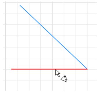
Placing an Angular Dimension – Two line Method
The Angular Dimension – Two line Method
The Three-Point Method
Select the first two points and move the cursor onto the third point as shown in Figure 17-9. The second point MUST be the vertex of the angle. The Angular Dimension icon will display as shown in Figure 17-9. Select the third point and drag the angular dimension to the desired location. See Figure 17-10.
Placing an Angular Dimension – Three Point Method
The Angular Dimension – Three Point Method
WORK ALONG: Drawing Models that Contain Inclined Lines
Step 1
Check the default project and if necessary, set it to Inventor Course.
Step 2
Using the NEW command start a new part file using the template: English-Modules Part (in).ipt.
Step 3
Save the file with the name: Inventor Workalong 17-1. (Figure Step 3A, 3B, and 3C)
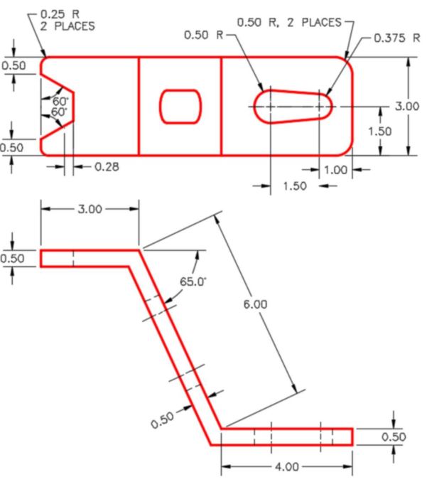
Dimensioned Multiview Drawing [Click to see image full size]
Auxiliary View
3D Model
Home View
Step 4
Start the Base sketch on the Front or XZ plane.
Step 5
Project the Center Point onto the sketch.
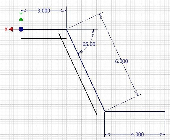
Step 6
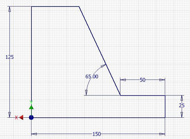
Draw the three top lines of the Front view and dimension them. Ensure that the sketch is fully constrained. (Figure Step 6)
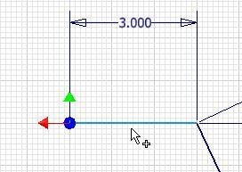
Step 7
Enter the OFFSET command. When prompted, select the top line. (Figure Step 7)
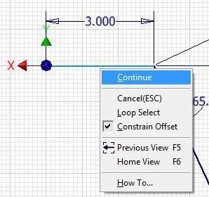
Step 8
Right click the mouse and in the Right-click menu, select Continue. Move the cursor down about 0.5 inches. The offset line will drag with it. Click to select the location. (Figure Step 8)
Step 9
Do the same for the other two lines. (Figure Step 9)
Step 10
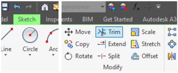
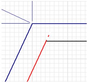
Enter the TRIM command. When prompted, select the overlapping end of the lines on the top intersection. (Figure Step 10A and 10B)
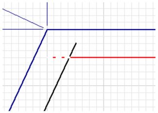
Step 11
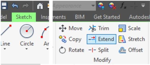
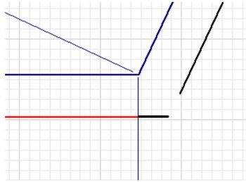
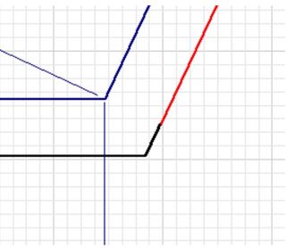
Enter the EXTEND command and extend the lines at the bottom intersection by selecting each of them. (Figure Step 11A and 11B)
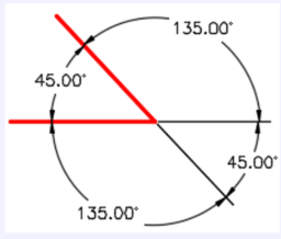
MUST KNOW: When inserting an angular dimension, only one dimension can be placed at a time even though there is a choice of placing the dimension in four different locations and two different angles. The figure on the right shows the four different angular dimension locations and the two different angles that can be inserted.
Step 12
Add three dimensions for the 0.5 thickness. The sketch should be fully constrained. (Figure Step 12)
Step 13
Press F6 to return to Home view.
Step 14
Extrude the sketch. (Figure Step 14)
Step 15
Start a new sketch on the top plane. Draw three lines and add the dimensions to fully constrain the sketch. (Figure Step 15)
Step 16
Extrude the sketch using the cut option. (Figure Step 16)
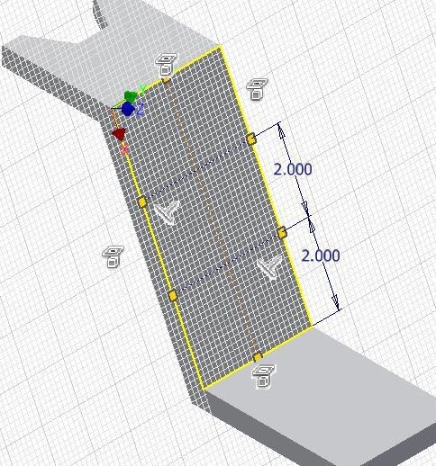
Step 17
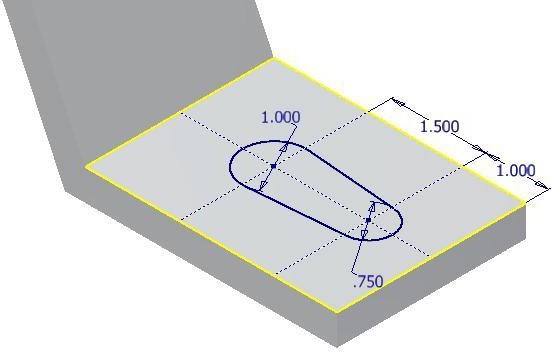
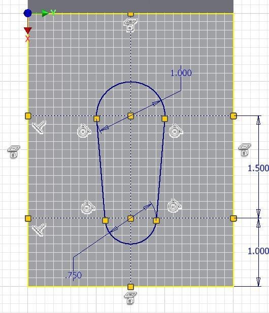
Start a new sketch on the inclined plane. Draw three construction lines and dimension them to locate the centre of the circles. Ensure that the lines are fully constrained. (Figure Step 17)
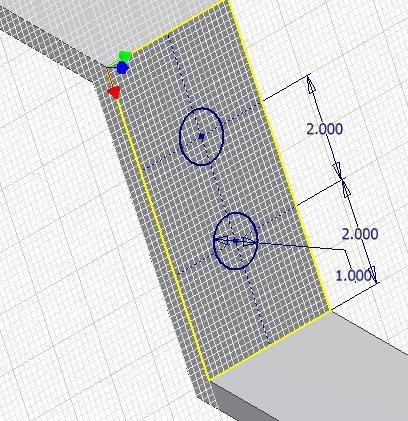
Step 18
Insert two circles locating their centers at the intersection of the construction lines. Dimension only one of them and then apply the Equal constrain to the other circle. (Figure Step 18)
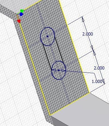
Step 19
Draw a line from one circle to the other. Don’t worry about constraining them tangent at this time. Ensure that the Snap On icon appears when you select the endpoint of the lines. (Figure 19A and 19B)
Step 19A
Step 19B
Step 20
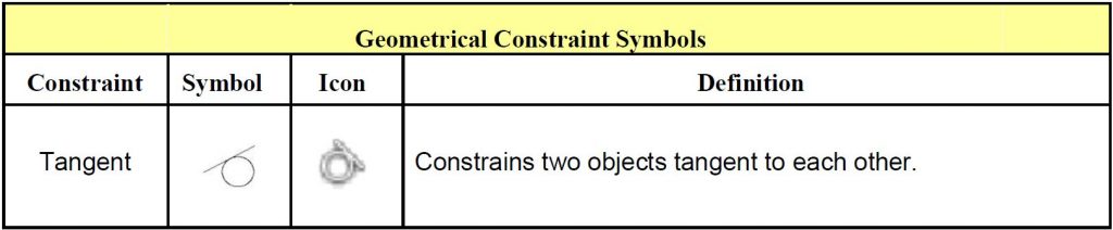
In the right-click menu, select Create Constrain – Tangent. (Figure Step 20).
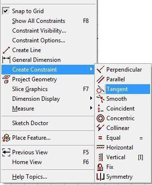
Step 20
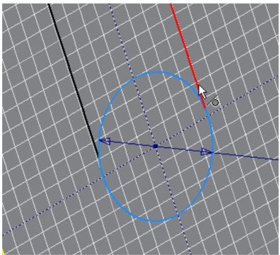
Step 21
Apply the Tangent constraint between the circle and the line. Repeat with the other circle. (Figure Step 21A and 21B)
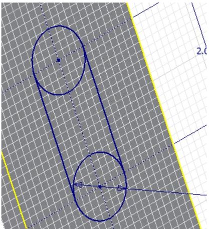
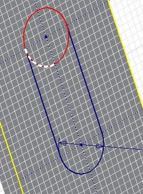
Step 22
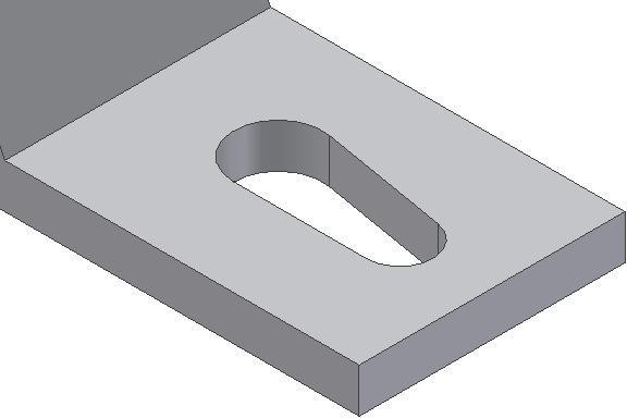
Trim the circles. This will take four steps. (Figure Step 22)
Step 23
Extrude the sketch. (Figure Step 23)
Step 24
Draw a 2D Sketch on the bottom plane. Using what you just learned, ensure that you constrain the lines tangent to the circles and then trim. (Figure Step 24A and 24B)
Step 25
Extrude the sketch. (Figure Step 25)
Step 26
Insert the fillets and change to the color: Orange to complete the solid model. (Figure Step 26)
Step 27
Save and close the part file.
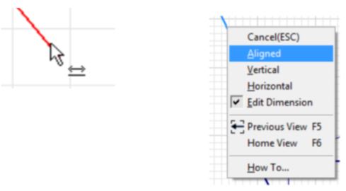
USER TIP: When inserting an aligned dimension and the Linear dimension icon displays, as shown in the figure immediate right, rather then the Aligned dimension icon, you can change that and force Inventor to place an aligned dimension. Right-click the mouse while the icon is displayed. In the Right-click menu, select Aligned as shown in the figure far right. This will also work in reverse. If the Aligned dimension icon displays, you can instruct Inventor to place a linear dimension either horizontal or vertical.
USER TIP: The TRIM command can be used to completely delete an object rather then just trimming it. If the object to be deleted does not intersect another object, simply press X and select the object to be deleted. If it intersects another object, it will take you more picks to delete it, but, it is still possible. The reason that it is best to use the TRIM command rather then the DELETE command to delete objects is the fact that TRIM has a shortcut (X) while the DELETE command does not have a shortcut. Entering a shortcut on the keyboard is faster then clicking an icon.
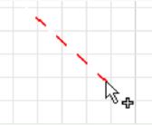
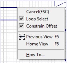
MUST KNOW: When offsetting most objects, the offset object can be geometrically constrained to the existing object. If the angle of the object that was offset is modified or the object is moved, the object that was offset will maintain its position in relation to the offset object. In the Right-click menu, during the OFFSET command, the Constrain Offset can be enabled or disabled as required. See the figure on the right.
Key Principles
Key Principles in Module 17
- You can guess at the angle when drawing inclined lines rather then entering the exact number of degrees. After the sketch is complete, the angles are dimensioned using the exact angle and Inventor will adjust the sketch to match.
- The TRIM command is used to trim a portion of an existing line or arc. The object to be trimmed must intersect an existing object. If it does not intersect an object, the complete object will be deleted instead of being trimmed.
- The EXTEND command is used to extend the length of an existing line or arc.
Lab Exercise 17-1
Time allowed: 60 minutes.
| Part Name | Project | Units | Template | Color | Material |
| Inventor Lab 17-1 | Inventor Course | Millimeters | Metric-Modules Part (mm).ipt | Beige | N/A |
Step 1
Project the Center Point onto the base plane.
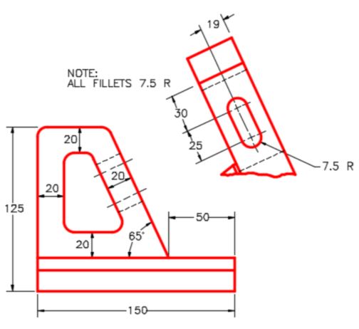
Step 2
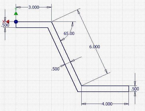
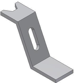
Note the location of X0Y0Z0. Draw the necessary sketches and extrude or revolve them to produce the solid model shown below. Apply all of the necessary geometrical and dimensional constraints to maintain the objects shape and size. (Figure Step 2A and 2B)
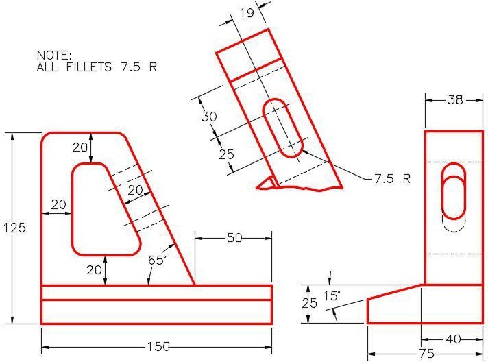
Dimensioned Multiview Drawing [Click to see image full size]
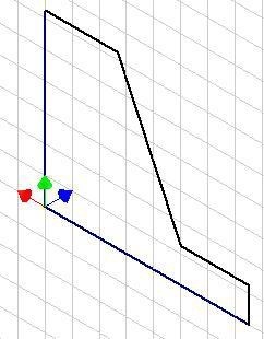
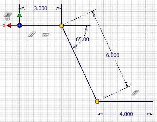
Suggested Base
Sketch – Front (XZ)
Plane
Step 3
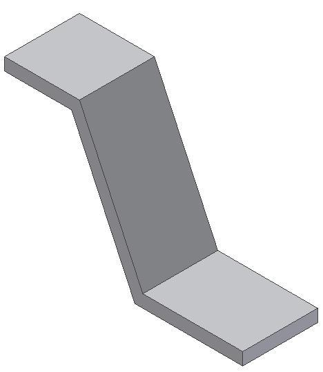
Apply the colour shown above. (Figure Step 3)
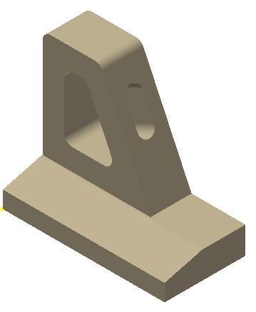
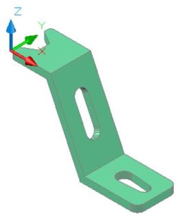
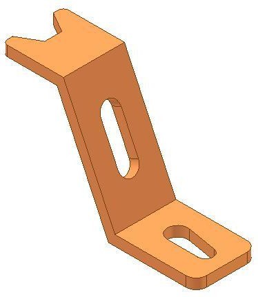
Completed Solid Model
Home View
Step 4
Create all fillets after the solid model is totally constructed.
Lab Exercise 17-2
Time allowed: 60 minutes.
| Part Name | Project | Units | Template | Color | Material |
| Inventor Lab 17-2 | Inventor Course | Inches | English-Modules Part (in).ipt | Nickle | N/A |
Step 1
Project the Center Point onto the base plane.
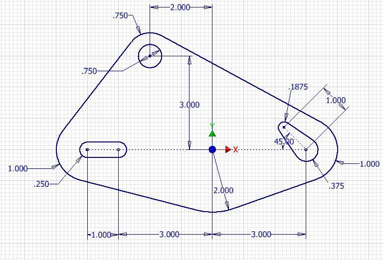
Step 2
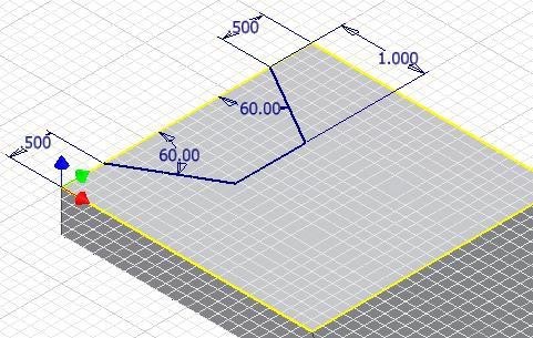
Note the location of X0Y0Z0. Draw the necessary sketches and extrude or revolve them to produce the solid model shown below. Apply all of the necessary geometrical and dimensional constraints to maintain the objects shape and size. (Figure Step 2A and 2B)
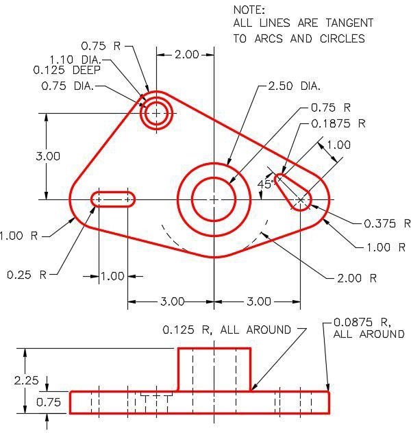
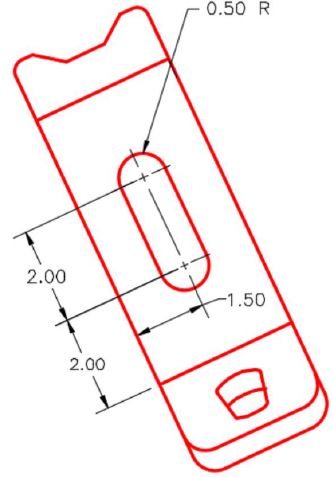
Dimensioned Multiview Drawing [Click to see image full size]
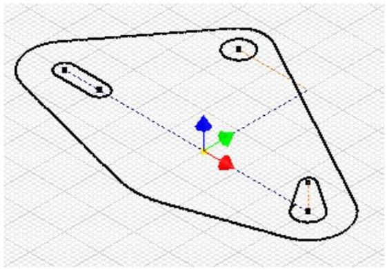
Suggested Base Sketch –
Top (XY) Plane) [Click to see image full size]
Step 3
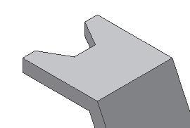
Apply the colour shown above. (Figure Step 3)
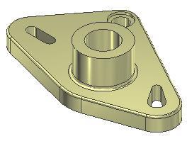
Completed Solid Model – Home View
Author’s
Step 4
Create all fillets after the solid model is totally constructed.