
4.3: Module 19 Work Features
- Page ID
- 19884

\( \newcommand{\vecs}[1]{\overset { \scriptstyle \rightharpoonup} {\mathbf{#1}} } \)
\( \newcommand{\vecd}[1]{\overset{-\!-\!\rightharpoonup}{\vphantom{a}\smash {#1}}} \)
\( \newcommand{\id}{\mathrm{id}}\) \( \newcommand{\Span}{\mathrm{span}}\)
( \newcommand{\kernel}{\mathrm{null}\,}\) \( \newcommand{\range}{\mathrm{range}\,}\)
\( \newcommand{\RealPart}{\mathrm{Re}}\) \( \newcommand{\ImaginaryPart}{\mathrm{Im}}\)
\( \newcommand{\Argument}{\mathrm{Arg}}\) \( \newcommand{\norm}[1]{\| #1 \|}\)
\( \newcommand{\inner}[2]{\langle #1, #2 \rangle}\)
\( \newcommand{\Span}{\mathrm{span}}\)
\( \newcommand{\id}{\mathrm{id}}\)
\( \newcommand{\Span}{\mathrm{span}}\)
\( \newcommand{\kernel}{\mathrm{null}\,}\)
\( \newcommand{\range}{\mathrm{range}\,}\)
\( \newcommand{\RealPart}{\mathrm{Re}}\)
\( \newcommand{\ImaginaryPart}{\mathrm{Im}}\)
\( \newcommand{\Argument}{\mathrm{Arg}}\)
\( \newcommand{\norm}[1]{\| #1 \|}\)
\( \newcommand{\inner}[2]{\langle #1, #2 \rangle}\)
\( \newcommand{\Span}{\mathrm{span}}\) \( \newcommand{\AA}{\unicode[.8,0]{x212B}}\)
\( \newcommand{\vectorA}[1]{\vec{#1}} % arrow\)
\( \newcommand{\vectorAt}[1]{\vec{\text{#1}}} % arrow\)
\( \newcommand{\vectorB}[1]{\overset { \scriptstyle \rightharpoonup} {\mathbf{#1}} } \)
\( \newcommand{\vectorC}[1]{\textbf{#1}} \)
\( \newcommand{\vectorD}[1]{\overrightarrow{#1}} \)
\( \newcommand{\vectorDt}[1]{\overrightarrow{\text{#1}}} \)
\( \newcommand{\vectE}[1]{\overset{-\!-\!\rightharpoonup}{\vphantom{a}\smash{\mathbf {#1}}}} \)
\( \newcommand{\vecs}[1]{\overset { \scriptstyle \rightharpoonup} {\mathbf{#1}} } \)
\( \newcommand{\vecd}[1]{\overset{-\!-\!\rightharpoonup}{\vphantom{a}\smash {#1}}} \)
\(\newcommand{\avec}{\mathbf a}\) \(\newcommand{\bvec}{\mathbf b}\) \(\newcommand{\cvec}{\mathbf c}\) \(\newcommand{\dvec}{\mathbf d}\) \(\newcommand{\dtil}{\widetilde{\mathbf d}}\) \(\newcommand{\evec}{\mathbf e}\) \(\newcommand{\fvec}{\mathbf f}\) \(\newcommand{\nvec}{\mathbf n}\) \(\newcommand{\pvec}{\mathbf p}\) \(\newcommand{\qvec}{\mathbf q}\) \(\newcommand{\svec}{\mathbf s}\) \(\newcommand{\tvec}{\mathbf t}\) \(\newcommand{\uvec}{\mathbf u}\) \(\newcommand{\vvec}{\mathbf v}\) \(\newcommand{\wvec}{\mathbf w}\) \(\newcommand{\xvec}{\mathbf x}\) \(\newcommand{\yvec}{\mathbf y}\) \(\newcommand{\zvec}{\mathbf z}\) \(\newcommand{\rvec}{\mathbf r}\) \(\newcommand{\mvec}{\mathbf m}\) \(\newcommand{\zerovec}{\mathbf 0}\) \(\newcommand{\onevec}{\mathbf 1}\) \(\newcommand{\real}{\mathbb R}\) \(\newcommand{\twovec}[2]{\left[\begin{array}{r}#1 \\ #2 \end{array}\right]}\) \(\newcommand{\ctwovec}[2]{\left[\begin{array}{c}#1 \\ #2 \end{array}\right]}\) \(\newcommand{\threevec}[3]{\left[\begin{array}{r}#1 \\ #2 \\ #3 \end{array}\right]}\) \(\newcommand{\cthreevec}[3]{\left[\begin{array}{c}#1 \\ #2 \\ #3 \end{array}\right]}\) \(\newcommand{\fourvec}[4]{\left[\begin{array}{r}#1 \\ #2 \\ #3 \\ #4 \end{array}\right]}\) \(\newcommand{\cfourvec}[4]{\left[\begin{array}{c}#1 \\ #2 \\ #3 \\ #4 \end{array}\right]}\) \(\newcommand{\fivevec}[5]{\left[\begin{array}{r}#1 \\ #2 \\ #3 \\ #4 \\ #5 \\ \end{array}\right]}\) \(\newcommand{\cfivevec}[5]{\left[\begin{array}{c}#1 \\ #2 \\ #3 \\ #4 \\ #5 \\ \end{array}\right]}\) \(\newcommand{\mattwo}[4]{\left[\begin{array}{rr}#1 \amp #2 \\ #3 \amp #4 \\ \end{array}\right]}\) \(\newcommand{\laspan}[1]{\text{Span}\{#1\}}\) \(\newcommand{\bcal}{\cal B}\) \(\newcommand{\ccal}{\cal C}\) \(\newcommand{\scal}{\cal S}\) \(\newcommand{\wcal}{\cal W}\) \(\newcommand{\ecal}{\cal E}\) \(\newcommand{\coords}[2]{\left\{#1\right\}_{#2}}\) \(\newcommand{\gray}[1]{\color{gray}{#1}}\) \(\newcommand{\lgray}[1]{\color{lightgray}{#1}}\) \(\newcommand{\rank}{\operatorname{rank}}\) \(\newcommand{\row}{\text{Row}}\) \(\newcommand{\col}{\text{Col}}\) \(\renewcommand{\row}{\text{Row}}\) \(\newcommand{\nul}{\text{Nul}}\) \(\newcommand{\var}{\text{Var}}\) \(\newcommand{\corr}{\text{corr}}\) \(\newcommand{\len}[1]{\left|#1\right|}\) \(\newcommand{\bbar}{\overline{\bvec}}\) \(\newcommand{\bhat}{\widehat{\bvec}}\) \(\newcommand{\bperp}{\bvec^\perp}\) \(\newcommand{\xhat}{\widehat{\xvec}}\) \(\newcommand{\vhat}{\widehat{\vvec}}\) \(\newcommand{\uhat}{\widehat{\uvec}}\) \(\newcommand{\what}{\widehat{\wvec}}\) \(\newcommand{\Sighat}{\widehat{\Sigma}}\) \(\newcommand{\lt}{<}\) \(\newcommand{\gt}{>}\) \(\newcommand{\amp}{&}\) \(\definecolor{fillinmathshade}{gray}{0.9}\)19
Module 19 Work Features
Wally Baumback
Learning Outcomes
When you have completed this module, you will be able to:
- Describe and apply the POLYGON, TANGENT CIRCLE, and THREAD commands.
- Describe work features including Work Points, Work Axes, and Work Planes and explain how they are used in model construction.
- Describe and apply the WORK POINT, WORK AXIS, and WORK PLANE commands.
Geometry Lesson: Regular Polygons
A polygon is defined as any plane figure bounded by straight lines. A regular polygon is a polygon that has equal angles, equal sides and can be inscribed in or circumscribed around a circle. The first eight regular polygons are shown in Figure 19-1.
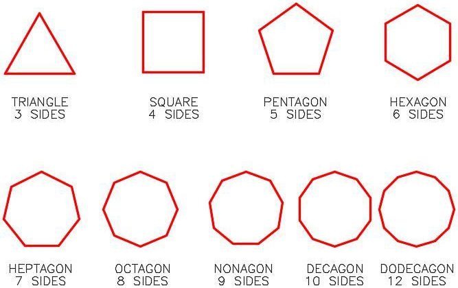
Regular Polygons
Work
Any regular polygon can be inscribed in or circumscribed around a circle as shown, using a hexagon, in Figure 19-2.
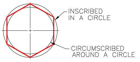
Inscribed and Circumscribed Regular Polygon
It is important to understand and know the geometry involved to construct a triangle, square, hexagon, and octagon as shown in Figure 19-3. Study each one and try to understand how they are constructed and the angles used to construct them.
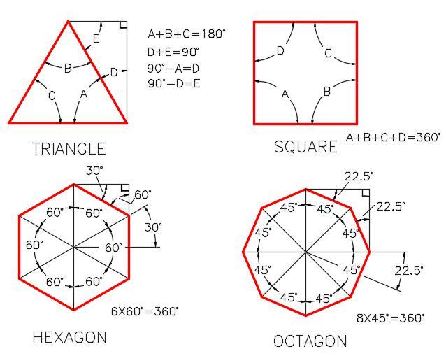
Geometry of Four Regular Polygons
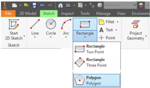
Inventor Command: POLYGON
The POLYGON command is used to draw a regular polygon on a 2D sketch. You can select the number of sides and choose between either an inscribed or a circumscribed polygon.
Shortcut: none
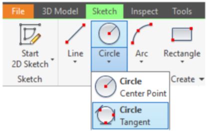
Inventor Command: TANGENT CIRCLE
The TANGENT CIRCLE command is used to draw a circle tangent to three lines.
Shortcut: none
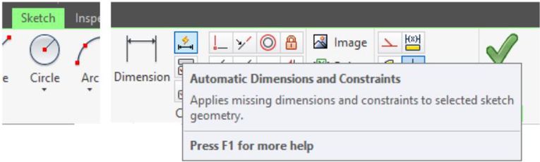
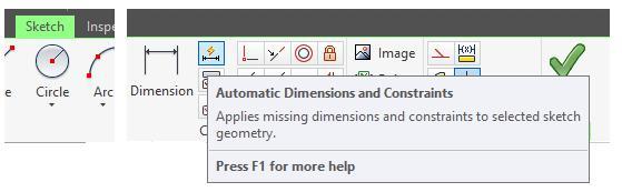
Inventor Command: AUTO DIMENSION
The AUTO DIMENSION command is used to add dimensions or constrains automatically to fully constrain a sketch.
Shortcut: none
Drawing Threads
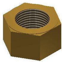
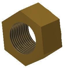
The THREAD command is used to draw exterior threads or interior threads on a 3D solid model. See Figure 19-4 The threads created using the THREAD command are not actual threads constructed on the model. They are simply a graphical representation of the threads. A real life solid model created from the Inventor part would not be threaded. Actual threads can be created but this is a much more advanced feature that is taught in the Inventor Advanced book. The thread specifications can be applied to the thread in the sketch and then be used when creating the working drawing of the part.
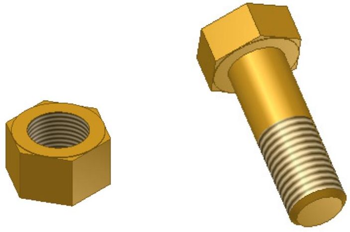
External and Internal Threads
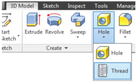
Inventor Command: THREAD
The THREAD command is used to draw a graphical representation of an outside or inside diameter thread. The thread specifications can also added to the thread properties.
Shortcut: none
WORK ALONG: Drawing Polygons and Threads – Part 1
Step 1
Using the NEW command start a new part file using the template: English-Modules Part (in).ipt.
Step 2
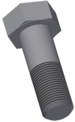
Save the file with the name: Inventor Workalong 19-1. (Figure Step 2A, 2B, and 2C)
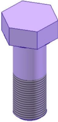
3D Model –
Home View
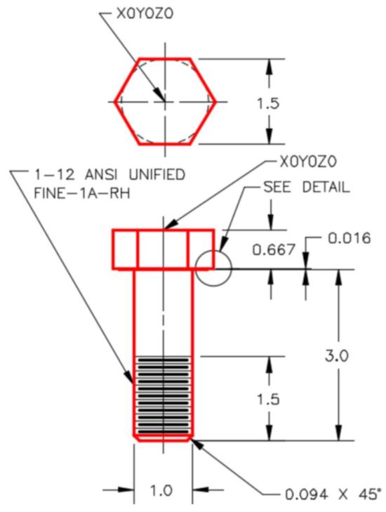
Dimensioned Multiview Drawing
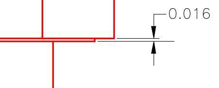
Detail
Step 3
Draw the Base sketch on the Top or XY plane.
Step 4
Project the Center Point onto the Base sketch.
Step 5
Enter the POLYGON command and set the number of sides to 6. (Figure Step 5)
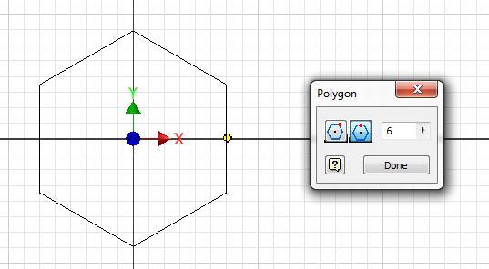
Step 6
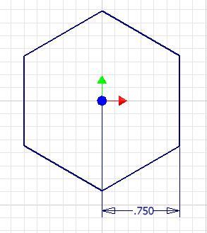
Enable the Circumscribed Polygon icon. Snap to the Center Point for the centre and select a radius of approximately 0.75 inches. (Figure Step 6)

Step 7
Add the dimension from the Center Point to the left line. (Figure Step 7)
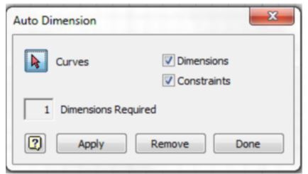
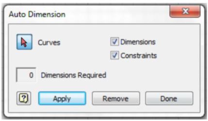
Step 8
Enter the AUTO DIMENSION command. Note that one dimension or constraint is required to fully constrain the sketch. Click Apply. (Figure Step 8A, 8B, and 8C
Step 9
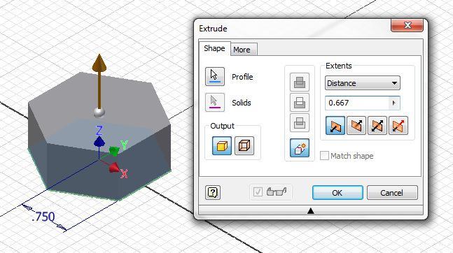
Extrude the hexagon in the negative Z direction. (Figure Step 9)
Step 10
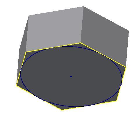
Start a new sketch on the bottom side of the Base model. Enter the TANGENT CIRCLE command. When prompted, select any three edges. (Figure Step 10)
Step 11
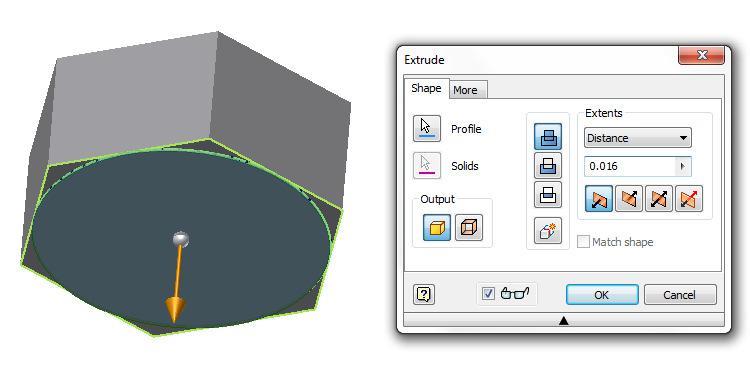
Extrude the circle 0.016 inches. Ensure that you enable the Join icon and extrude it away from the bolt head. (Figure Step 11)
Step 12
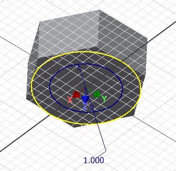
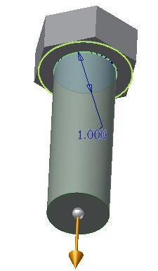
Start a new sketch on the extruded circle. Draw and dimension a 1 inch circle using the centre of the circle to snap to. Extrude the circle 3 inches. (Figure Step 12A and 12B)
Step 13
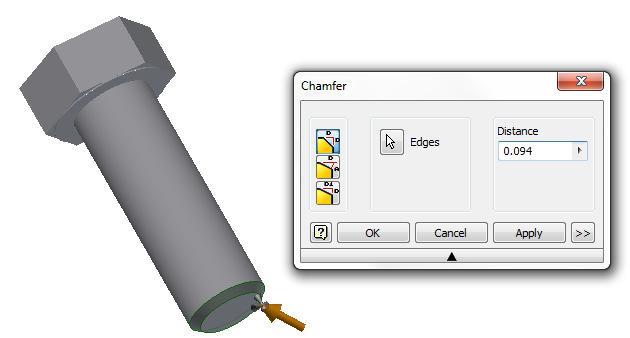
Using the CHAMFER command, chamfer the bottom of the bolt. (Figure Step 13)
Step 14
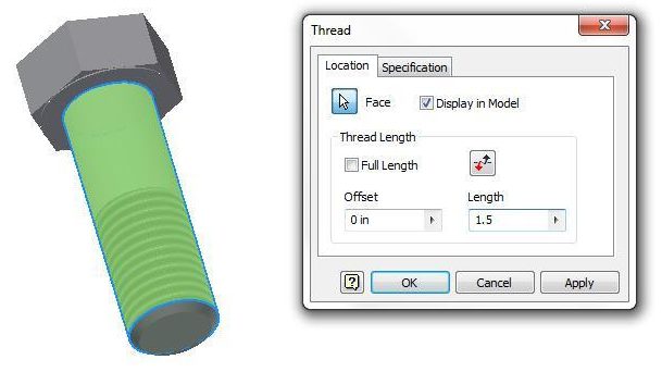
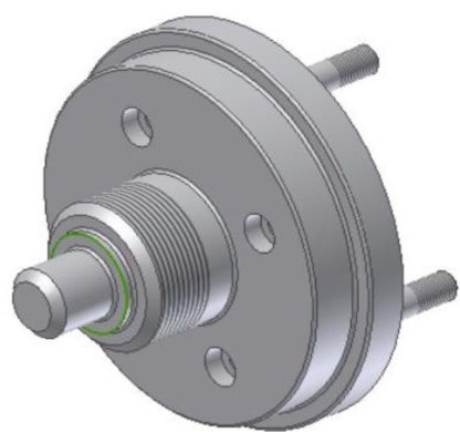
Enter the THREAD command. Enable the Location tab and set the Length to 1.5 and then select the cylinder as the face to thread. Do not close the dialogue box. (Figure Step 14)
Step 15
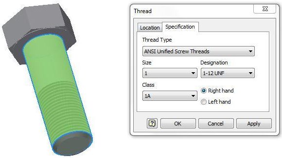
Enable the Specification tab. Set the thread specifications as shown in the figure. Click OK to execute the command. (Figure Step 15A and 15B)
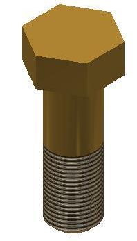
Step 16
Change the view to the Home view and change the colour to: Metal-Brass. (Figure Step 16)
Step 17
Save and close the file.
MUST KNOW: The threads created by the THREAD command are not actual threads constructed on the model. They are simply a graphical representation of the threads. A real life solid model created from the Inventor part file would not be threaded.WORK ALONG: Drawing Polygons and Threads – Part 2
Step 1
Check the default project and if necessary, set it to Inventor Course.
Step 2
Using the NEW command start a new part file using the template: English-Modules Part (in).ipt.
Step 3
Save the file with the name: Inventor Workalong 19-2.
Step 4
Using what you learned in the last workalong, construct the nut shown in the multiview drawing. (Figure Step 4A and 4B)
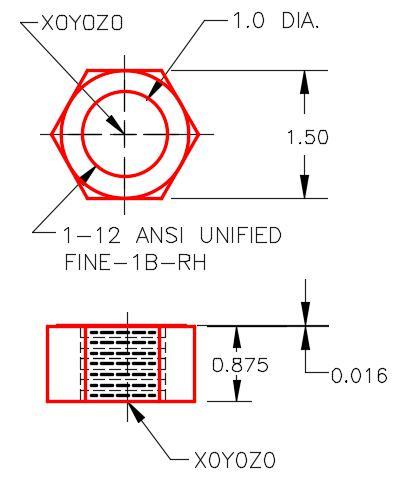
Dimensioned Multiview Drawing
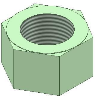
Step 5
Change the colour to: Metal-Brass. (Figure Step 5A and 5B)
Work Features
Work Features consists of points, axes, and planes that can be inserted on a solid model or in Model space. They are used as a construction aids to draw the model. You can insert them when existing geometry cannot be used to add geometry. The three work features available in Inventor are the work point, the work axis, and the work plane. See Figure 19-5. This module is an introduction to work features only and will teach the user how to create and use them in part modeling. They are also used in assemblies.
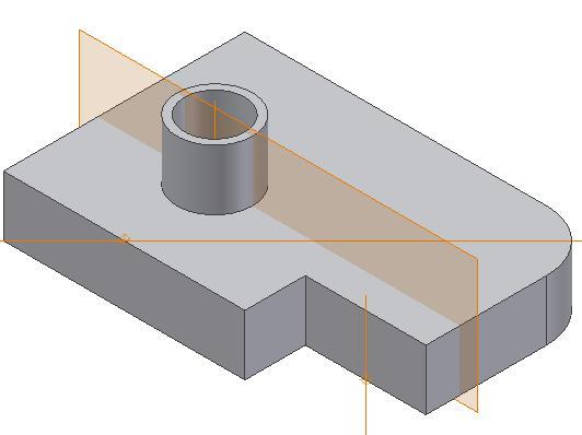
Work Features
Work Points
A Work Point is a parametric construction point or a single XYZ location that is inserted and then used as a work feature. Once a Work Point is inserted on the model, it can be projected onto part faces, linear edges, or onto an arc or circle using the PROJECT GEOMETRY command. Work Points can also be constrained to the centre points of arcs, circles, and ellipses. In this module, inserting Work Points on the model or in 3D space will be taught.
Work Axes
A Work Axis is a parametric construction line or two XYZ locations joined by a line that is inserted and then used as a work feature. Even though a Work Axis appears as a specified length, as far as Inventor is concerned, it is infinite in length and can be expanded to any length required.
Use Work Axes when creating models to mark symmetry lines, centre lines, or distances between revolved feature axes. Work Axes can be used along the symmetry lines of circular features such as cylinders, shafts, or holes. They can also be created as a work axis on a linear edge, a sketch line, or a 3D sketch line.
Work Planes
A Work Plane is parametric construction plane or four XYZ locations joined by lines inserted on the model or in model space and then used as a work feature. Even though a Work Plane appears as a rectangular plane of a given size, it is actually infinite in size and can be expanded to any size required.
Work Planes can be placed at any orientation in space, offset from existing faces, or rotated around an axis or edge. A work plane can be used as a sketch plane and dimensioned or constrained to other features or components. Each work plane has its own internal coordinate system. The order in which geometry is selected determines the origin and positive directions of the coordinate system axes.
Inventor Command: WORK POINT
The WORK POINT command is used to insert a Work Point on the model or in Model space.
Shortcut: . (period)
Inventor Command: WORK AXIS
The WORK AXIS command is used to insert a Work Axis on the model or in Model space.
Shortcut: / (forward slash)
Inventor Command: WORK PLANE
The WORK PLANE command is used to insert a Work Plane on the model or in Model space.
Shortcut:] (right bracket)
WORK ALONG: Creating Work Features
Step 1
Check the default project and if necessary, set it to Inventor Course.
Step 2
Using the NEW command start a new part file using the template: English-Modules Part (in).ipt.
Step 3
Save the file with the name: Inventor Workalong 19-3.
Step 4
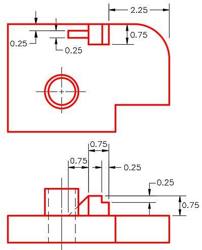
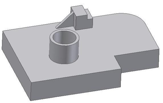
Create the solid model shown in the figures. (Figure Step 4A and 4B)
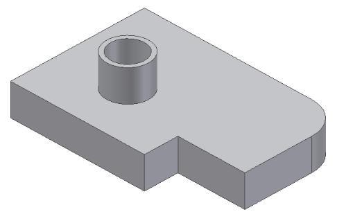
3D Model – Home View
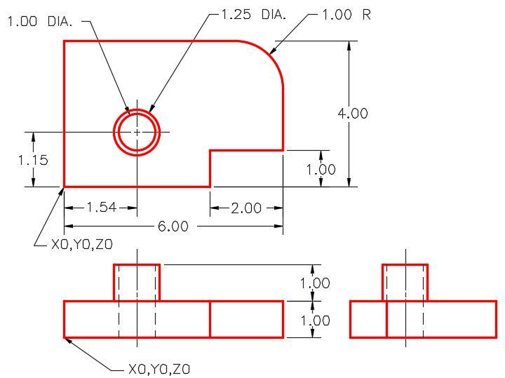
Dimensioned Multiview Drawing [Click to see image full size]
Step 5
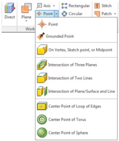
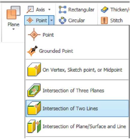
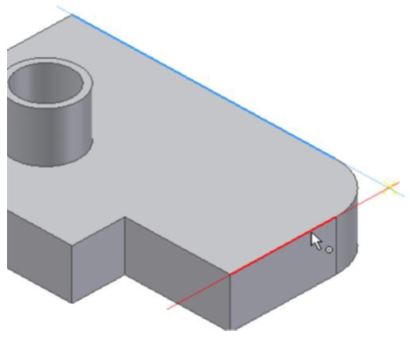
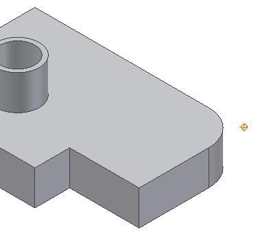
Insert a Work Point at the apparent intersection of two edges. Click the WORK POINT command and then Intersection of Two Lines. Select the edges shown in the figure. Note how they highlight and extend. (Figure Step 5A, 5B, and 5C)
Step 6
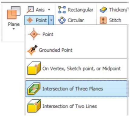
Insert a Work Point at the intersection of three planes. Click the WORK POINT command and then Intersection of Three Planes. Select the planes shown in the figures. (Figure Step 6A, 6B, 6C, 6D, and 6E)
Step 7
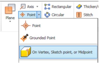
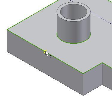
To insert a Work Point at the midpoint of an edge. Click the WORK POINT command and then On Vertex, Sketch point, or Midpoint. Snap to the midpoint of the edge shown in the figure. The midpoint will highlight with a yellow work point symbol. Select it when it appears. (Figure Step 7A, 7B, and 7C)
Step 8
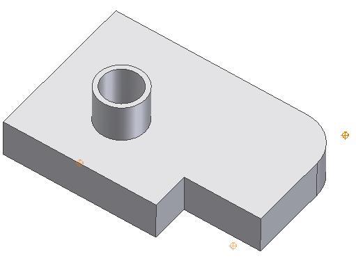
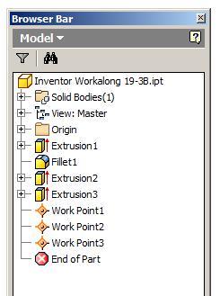
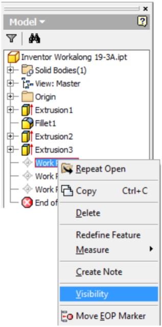
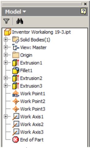
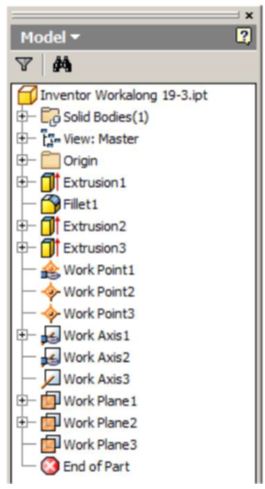
Work Features will display as items in the Browser bar. Note the three Work Points that you just inserted. The visibility of Work Features can be enabled or disabled in the Right-click menu. (Figure 8A and 8B)
Step 9
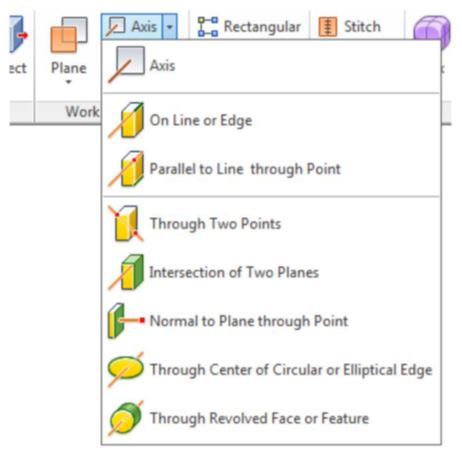
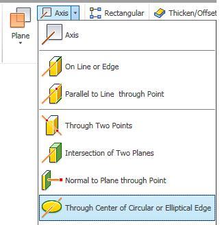
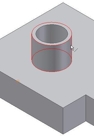
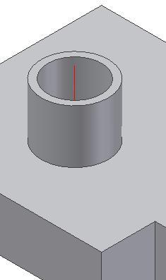
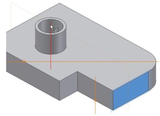
Insert a Work Axis on the centerline of the cylinder. Enter the WORK AXIS command and then Through Center of Circular or Elliptical Edge. Select the cylinder as shown in the figure. Note how the cylinder highlights. The axis will appear as a colored line. (Figure Step 9A, 9B, and 9C)
Step 10
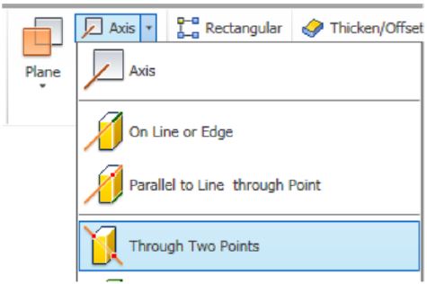
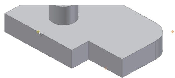
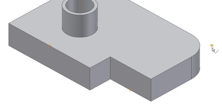
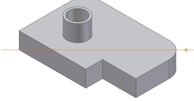
Insert a Work Axis between two Work Points. Enter the WORK AXIS command and then Through Two Points. Select the Work Points on the front edge and the back corner. (Figure Step 10A, 10B, 10C, and 10D)
Step 11
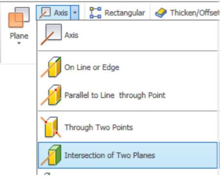
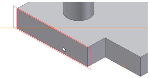
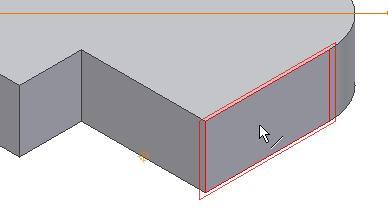
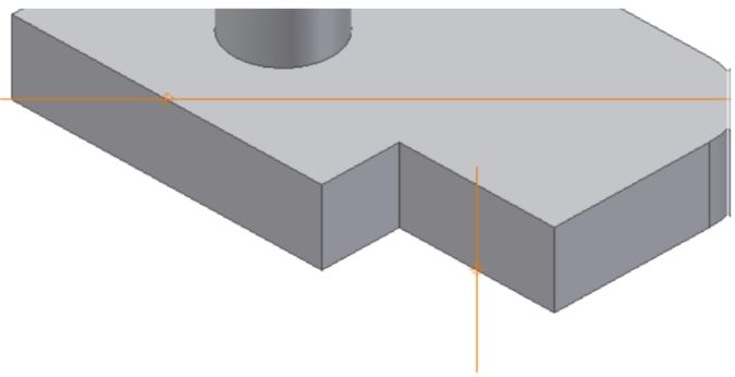
Insert a Work Axis at the intersection of two non-parallel faces. Enter the WORK AXIS command and then Intersection of Two Planes. Select the face on the left side and then the face on the right side. The Work Axis will appear at the apparent intersection of the two faces. (Figure Step 11A, 11B, 11C, and 11D)
Step 12
Work Features will display as items in the Browser bar. Note the three Work Axes that you just inserted. (Figure Step 12)
Step 13
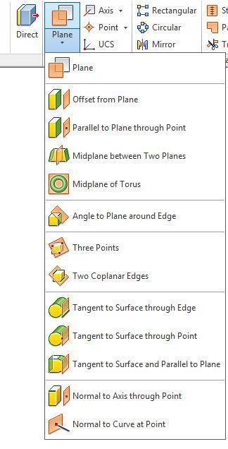
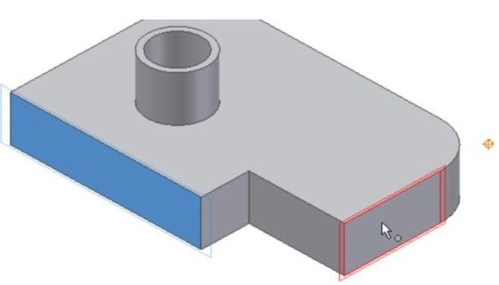
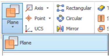
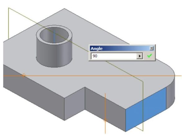
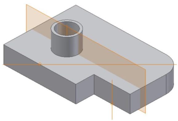
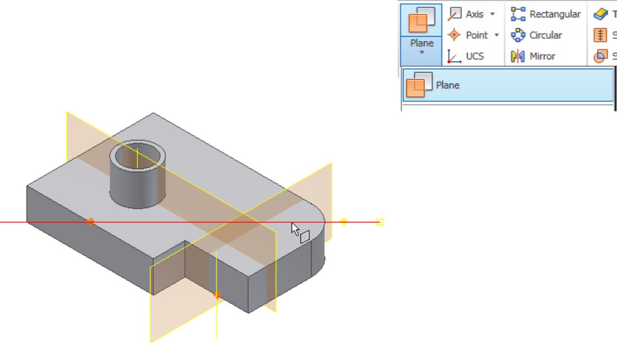
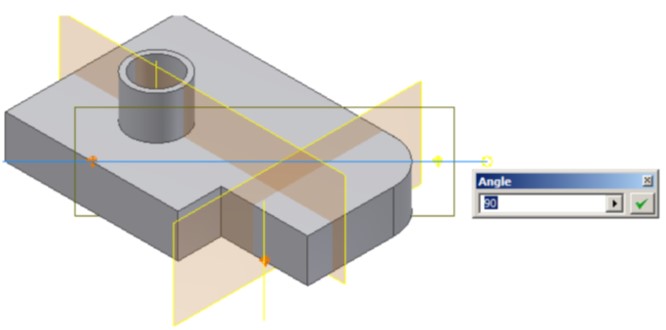
Insert a Work Plane from an existing face and through a Work Axis at a specified angle. Enter the WORK PLANE command and then Plane. Select the face on the right side of the model and then select the Work Axis at the centre of the cylinder. Enter the angle between the new Work Plane and the face. In this case, 90 degrees or perpendicular. (Figure Step 13A, 13B, 13C, and 13D)
Step 14
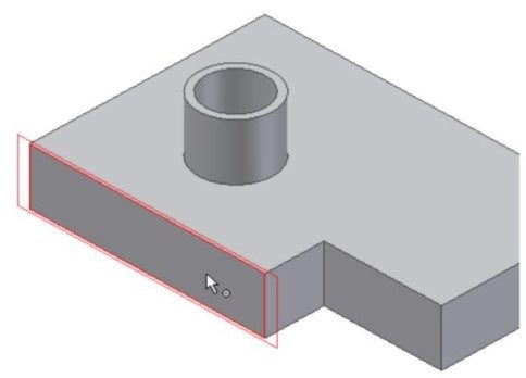
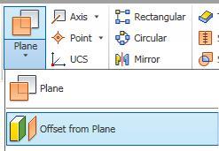
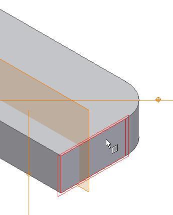
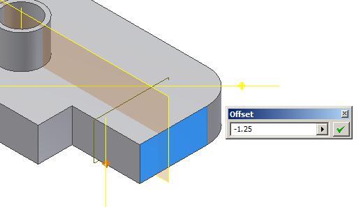
Insert an offset Work Plane. Enter the WORK PLANE command and then Offset from Plane. Select the face on the right side. Hold down the left mouse button and drag the plane into the model. The Offset dialogue box will display. Enter the offset distance of -1.25 inches. (Figure Step 14A, 14B, and 14C)
Step 15
Move the cursor to the edge of the newly inserted work plane and when the double arrow icon appears, press and hold down the left mouse button. While holding it down, drag it to enlarge the plane. Do this for all four corners. (Figure Step 15A and 15B)
Step 16
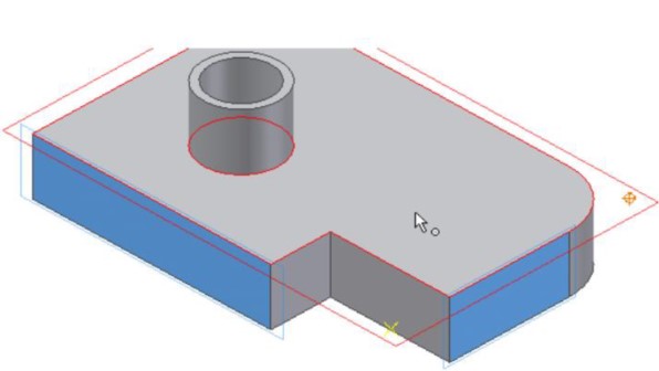
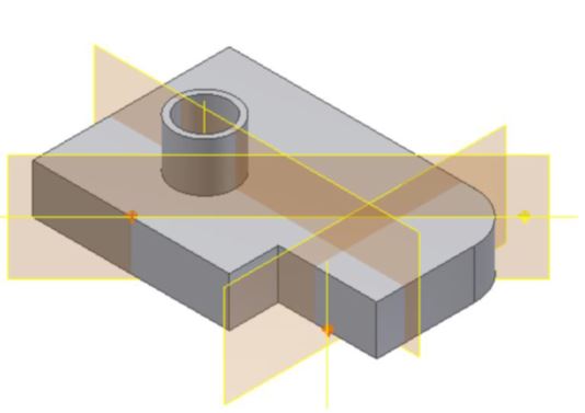
Insert a Work Plane on a work axis and at an angle to an existing plane. Enter the WORK PLANE command and then Plane. Select the Work Axis shown in the figure. Select the bottom plane next and enter the angle of 90 degrees. (Figure Step 16A, 16B, 16C, 16D, and 16E)
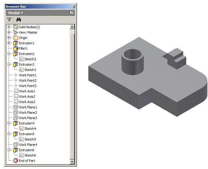
Step 17
The Browser bar should now appear as shown in the figure. (Figure Step 17)
Step 18
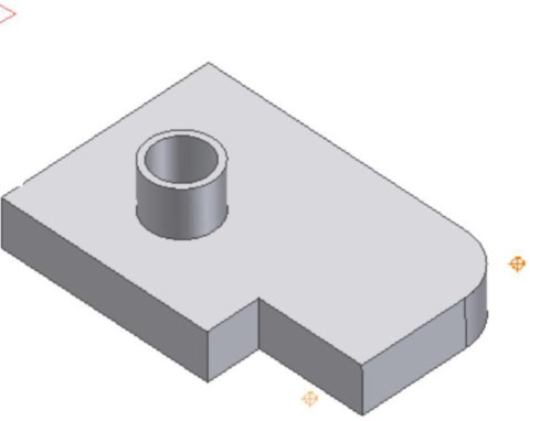
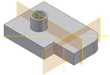
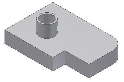
Disable the visibility of all Work Features. Your solid model should appear as shown in the figure. (Figure Step 18)
Dimensioned Multiview Drawing
3D Model – Home View
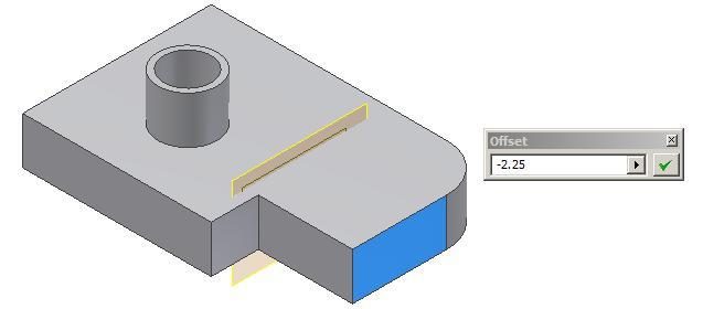
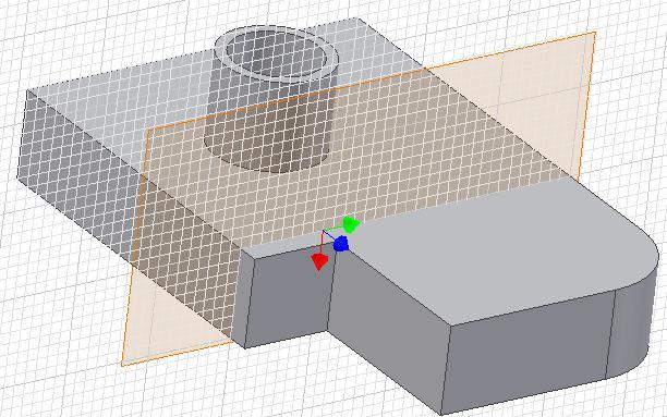
Step 19
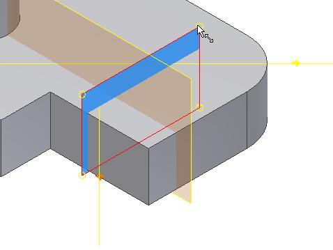
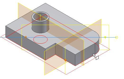
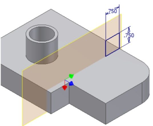
Using the offset method, insert a Work Plane -2.25 inches from the right side face. Expand the size of the Work Plane. Start a new sketch on the Work Plane. (Figure Step 19A and 19B)
Step 20
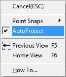
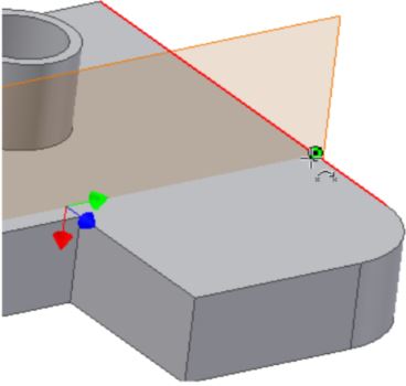
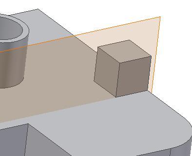
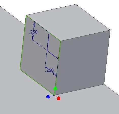
Enter the TWO POINT RECTANGLE command and right click the mouse. Ensure that AutoProject is enabled. Draw a rectangle by snapping to the bottom right corner. Dimension the square and ensure it is fully constrained. Extrude the sketch. (Figure Step 20A, 20B, 20C, and 20D)
Step 21
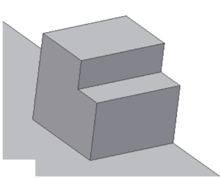
Start a new sketch and draw two lines. Dimension and extrude it. (Figure Step 21A and 21B)
Step 22
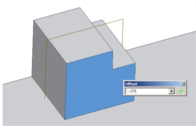
Insert a Work Plane -0.375 inches in from the front face. (Figure Step 22)
Step 23
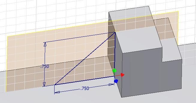
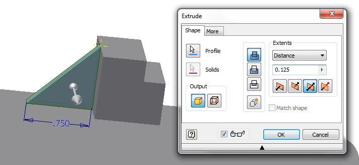
Draw a triangle and insert two dimensions to fully constrain it. (Figure Step 23)
Step 24
Extrude the sketch 0.125 inches in both directions to complete the part. (Figure Step 24)
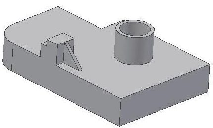
Step 25
Disable the visibility of all Work Features. The completed solid model should appear as shown in the figure. (Figure Step 25)
Step 26
Change to the Home view. (Figure Step 26)
Step 27
Save and close the part.
Key Principles
Key Principles in Module 19
- The POLYGON command is used to draw a regular polygon on a 2D sketch. You can select the number of sides and choose between either an inscribed or a circumscribed polygon.
- The threads created by the THREAD command are not actual threads constructed on the model. They are simply a graphical representation of the threads.
- The TANGENT CIRCLE command is used to draw a circle tangent to three lines.
- The AUTO DIMENSION command is used to add dimensions or constrains automatically to fully constrain a sketch.
- The three Work Features available in Inventor are the Work Point, the Work Axis, and the Work Plane.
- A Work Point is a parametric construction point or a single XYZ location that is inserted and then used as a Work Feature.
- A Work Axis is a parametric construction line or two XYZ locations joined by a line that is inserted and then used as a Work Feature.
- A Work Plane is parametric construction plane or four XYZ locations joined by lines inserted on the model or Model space and then used as a Work Feature.
Lab Exercise 19-1
Time allowed: 90 minutes.
| Part Name | Project | Units | Template | Color | Material |
| Inventor Lab Lab 19-1 | Inventor Course | Millimeters | Metric – Modules Part (mm).ipt | Chrome – Black Polished | N/A |
Step 1
Draw the Base sketch on the Front view.
Step 2
Project the Center Point onto the Base plane.
Step 3
Note the location of X0Y0Z0. Draw the necessary sketches and EXTRUDE them to produce the solid model shown below. Apply all of the necessary geometrical and dimensional constraints to maintain the objects shape and size. (Figure Step 3A, 3B, 3C, 3D, and 3E)
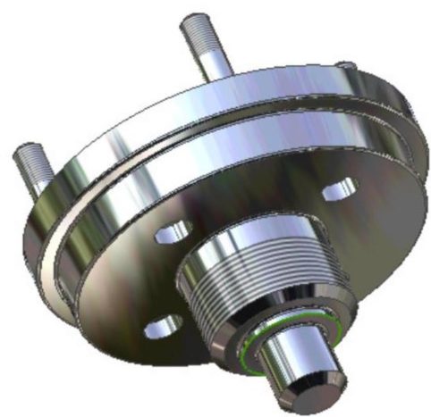
3D Model – Orbited View
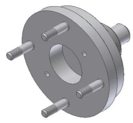
3D Model – Home View
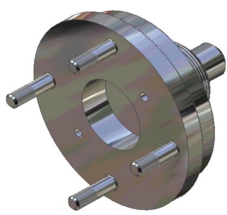
Solid Model – Home View
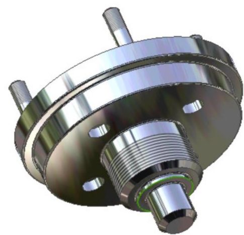
3D Model – Orbited View
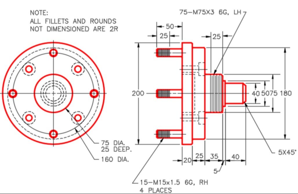
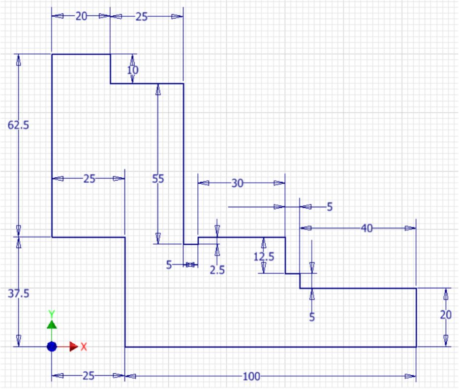
Left Side View – Multiview Drawing [Click to see image full size]
Right Side View – Multiview Drawing [Click to see image full size]
Step 4
Create the fillets and chamfers after the model is totally constructed.
Step 5
Apply the colour shown above.
Lab Exercise 19-2
Time allowed: 90 minutes.
| Part Name | Project | Units | Template | Color | Material |
| Inventor Lab Lab 19-2 | Inventor Course | Millimeters | Metric – Modules Part (mm).ipt | Chrome – Black Polished | N/A |
Step 1
Draw the Base sketch on the Right Side view.
Step 2
Project the Center Point onto the Base plane.
Step 3
Note the location of X0Y0Z0. Draw the same model you just drew in Lab Exercise 19-1. In this exercise, REVOLVE the Base sketch and then add sketches and extrude them to complete the model. Apply all of the necessary geometrical and dimensional constraints to maintain the objects shape and size. (Figure Step 3A, 3B, 3C, and 3D)
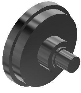
3D Model – Orbited View
3D Model – Home View
Solid Model – Home View
Solid Model – Orbited View
Step 4
Create the fillets and chamfers after the model is totally constructed.
Step 5
Apply the colour shown above.
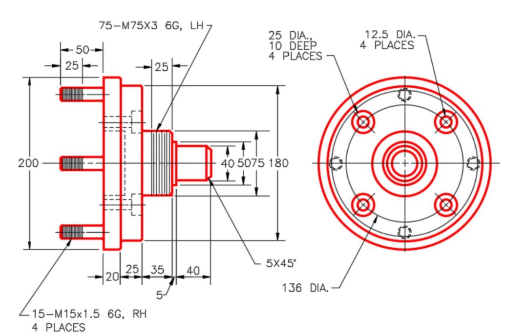
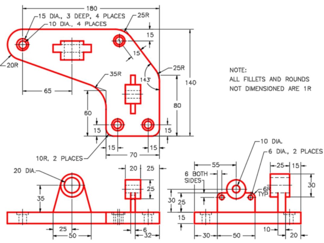
Lab Exercise 19-3
Time allowed: 90 minutes.
| Part Name: Inventor Lab 19-3 | Project: Inventor Course | Units: Millimeters |
| Template: Metric – Modules Part (mm).ipt | Color: Galvanized (texture) | Material: N/A |
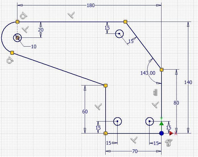
Step 1
Project the Center Point onto the Base sketch.
Step 2
Draw the necessary sketches and extrude or revolve them to produce the solid model shown below. Apply all of the necessary geometrical and dimensional constraints to maintain the objects shape and size. (Figure Step 2A, 2B, 2C, 2D, and 2E)
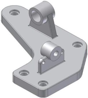
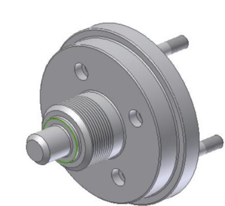
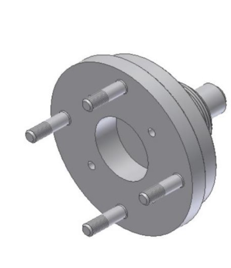
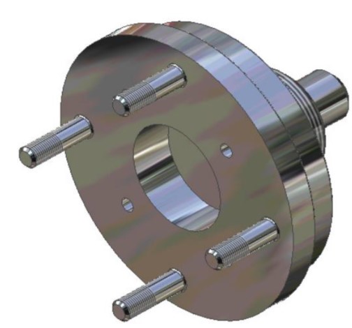
3D Model – Home View
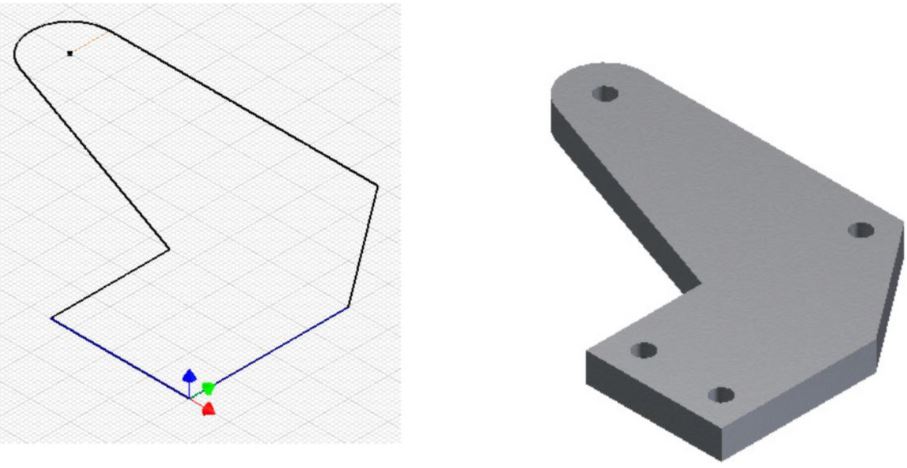
Suggested Base Sketch – Author’s Base Model Top (XY) Plane
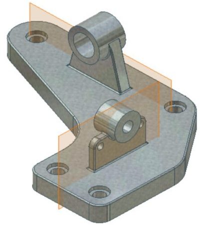
Solid Model – Home View
With Work Planes
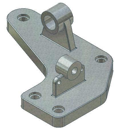
Solid Model – Home View
Step 3
Create the fillets and chamfers after the model is totally constructed.
Step 4
Apply the colour shown above.