7.6: CAE1000 Assembly Tutorial
- Page ID
- 31558
\( \newcommand{\vecs}[1]{\overset { \scriptstyle \rightharpoonup} {\mathbf{#1}} } \)
\( \newcommand{\vecd}[1]{\overset{-\!-\!\rightharpoonup}{\vphantom{a}\smash {#1}}} \)
\( \newcommand{\id}{\mathrm{id}}\) \( \newcommand{\Span}{\mathrm{span}}\)
( \newcommand{\kernel}{\mathrm{null}\,}\) \( \newcommand{\range}{\mathrm{range}\,}\)
\( \newcommand{\RealPart}{\mathrm{Re}}\) \( \newcommand{\ImaginaryPart}{\mathrm{Im}}\)
\( \newcommand{\Argument}{\mathrm{Arg}}\) \( \newcommand{\norm}[1]{\| #1 \|}\)
\( \newcommand{\inner}[2]{\langle #1, #2 \rangle}\)
\( \newcommand{\Span}{\mathrm{span}}\)
\( \newcommand{\id}{\mathrm{id}}\)
\( \newcommand{\Span}{\mathrm{span}}\)
\( \newcommand{\kernel}{\mathrm{null}\,}\)
\( \newcommand{\range}{\mathrm{range}\,}\)
\( \newcommand{\RealPart}{\mathrm{Re}}\)
\( \newcommand{\ImaginaryPart}{\mathrm{Im}}\)
\( \newcommand{\Argument}{\mathrm{Arg}}\)
\( \newcommand{\norm}[1]{\| #1 \|}\)
\( \newcommand{\inner}[2]{\langle #1, #2 \rangle}\)
\( \newcommand{\Span}{\mathrm{span}}\) \( \newcommand{\AA}{\unicode[.8,0]{x212B}}\)
\( \newcommand{\vectorA}[1]{\vec{#1}} % arrow\)
\( \newcommand{\vectorAt}[1]{\vec{\text{#1}}} % arrow\)
\( \newcommand{\vectorB}[1]{\overset { \scriptstyle \rightharpoonup} {\mathbf{#1}} } \)
\( \newcommand{\vectorC}[1]{\textbf{#1}} \)
\( \newcommand{\vectorD}[1]{\overrightarrow{#1}} \)
\( \newcommand{\vectorDt}[1]{\overrightarrow{\text{#1}}} \)
\( \newcommand{\vectE}[1]{\overset{-\!-\!\rightharpoonup}{\vphantom{a}\smash{\mathbf {#1}}}} \)
\( \newcommand{\vecs}[1]{\overset { \scriptstyle \rightharpoonup} {\mathbf{#1}} } \)
\( \newcommand{\vecd}[1]{\overset{-\!-\!\rightharpoonup}{\vphantom{a}\smash {#1}}} \)
\(\newcommand{\avec}{\mathbf a}\) \(\newcommand{\bvec}{\mathbf b}\) \(\newcommand{\cvec}{\mathbf c}\) \(\newcommand{\dvec}{\mathbf d}\) \(\newcommand{\dtil}{\widetilde{\mathbf d}}\) \(\newcommand{\evec}{\mathbf e}\) \(\newcommand{\fvec}{\mathbf f}\) \(\newcommand{\nvec}{\mathbf n}\) \(\newcommand{\pvec}{\mathbf p}\) \(\newcommand{\qvec}{\mathbf q}\) \(\newcommand{\svec}{\mathbf s}\) \(\newcommand{\tvec}{\mathbf t}\) \(\newcommand{\uvec}{\mathbf u}\) \(\newcommand{\vvec}{\mathbf v}\) \(\newcommand{\wvec}{\mathbf w}\) \(\newcommand{\xvec}{\mathbf x}\) \(\newcommand{\yvec}{\mathbf y}\) \(\newcommand{\zvec}{\mathbf z}\) \(\newcommand{\rvec}{\mathbf r}\) \(\newcommand{\mvec}{\mathbf m}\) \(\newcommand{\zerovec}{\mathbf 0}\) \(\newcommand{\onevec}{\mathbf 1}\) \(\newcommand{\real}{\mathbb R}\) \(\newcommand{\twovec}[2]{\left[\begin{array}{r}#1 \\ #2 \end{array}\right]}\) \(\newcommand{\ctwovec}[2]{\left[\begin{array}{c}#1 \\ #2 \end{array}\right]}\) \(\newcommand{\threevec}[3]{\left[\begin{array}{r}#1 \\ #2 \\ #3 \end{array}\right]}\) \(\newcommand{\cthreevec}[3]{\left[\begin{array}{c}#1 \\ #2 \\ #3 \end{array}\right]}\) \(\newcommand{\fourvec}[4]{\left[\begin{array}{r}#1 \\ #2 \\ #3 \\ #4 \end{array}\right]}\) \(\newcommand{\cfourvec}[4]{\left[\begin{array}{c}#1 \\ #2 \\ #3 \\ #4 \end{array}\right]}\) \(\newcommand{\fivevec}[5]{\left[\begin{array}{r}#1 \\ #2 \\ #3 \\ #4 \\ #5 \\ \end{array}\right]}\) \(\newcommand{\cfivevec}[5]{\left[\begin{array}{c}#1 \\ #2 \\ #3 \\ #4 \\ #5 \\ \end{array}\right]}\) \(\newcommand{\mattwo}[4]{\left[\begin{array}{rr}#1 \amp #2 \\ #3 \amp #4 \\ \end{array}\right]}\) \(\newcommand{\laspan}[1]{\text{Span}\{#1\}}\) \(\newcommand{\bcal}{\cal B}\) \(\newcommand{\ccal}{\cal C}\) \(\newcommand{\scal}{\cal S}\) \(\newcommand{\wcal}{\cal W}\) \(\newcommand{\ecal}{\cal E}\) \(\newcommand{\coords}[2]{\left\{#1\right\}_{#2}}\) \(\newcommand{\gray}[1]{\color{gray}{#1}}\) \(\newcommand{\lgray}[1]{\color{lightgray}{#1}}\) \(\newcommand{\rank}{\operatorname{rank}}\) \(\newcommand{\row}{\text{Row}}\) \(\newcommand{\col}{\text{Col}}\) \(\renewcommand{\row}{\text{Row}}\) \(\newcommand{\nul}{\text{Nul}}\) \(\newcommand{\var}{\text{Var}}\) \(\newcommand{\corr}{\text{corr}}\) \(\newcommand{\len}[1]{\left|#1\right|}\) \(\newcommand{\bbar}{\overline{\bvec}}\) \(\newcommand{\bhat}{\widehat{\bvec}}\) \(\newcommand{\bperp}{\bvec^\perp}\) \(\newcommand{\xhat}{\widehat{\xvec}}\) \(\newcommand{\vhat}{\widehat{\vvec}}\) \(\newcommand{\uhat}{\widehat{\uvec}}\) \(\newcommand{\what}{\widehat{\wvec}}\) \(\newcommand{\Sighat}{\widehat{\Sigma}}\) \(\newcommand{\lt}{<}\) \(\newcommand{\gt}{>}\) \(\newcommand{\amp}{&}\) \(\definecolor{fillinmathshade}{gray}{0.9}\)This tutorial is to provide a review of all the things we have done with CAE1000 in this chapter and to put all the instructions in one place. There are also a few alternative ways in modeling the assembly that are presented here that weren’t presented in the previous video exercises of this chapter.
We modeled CAE1000 as a SolidWorks assembly applying standard mates to planes and faces as well as using toolbox components in design. To model the assembly, you needed the CAE1000 Part files. You should remember modeling most these parts throughout the textbook. When downloading the parts, it is crucial to remember to extract all the files before trying to use them. This is because the files are given in a compressed zip folder format.

INSERT THE FIRST COMPONENTS
Open SolidWorks, download and extract the part files, and start a new assembly file. Check your units to make sure they are in inches.
As soon as you open the assembly, the Insert Components command should activate with a file folder. Navigate to the downloaded part files via the file folder. Select CAE1001 from the list, click “Open” in the dialog box, and confirm the command to align the part and assembly origins.
Activate the “Insert Components” command from the assembly tab of the CommandManager, click “browse” and select CAE1002 to insert next. Insert this part anywhere in the graphics area that is NOT the origin.
Rotate the part into the approximate assembly orientation by holding down the RIGHT mouse button and moving the mouse.

INITIAL COINCIDENT MATES
Activate the Mates command from the Assembly Tab of the CommandManager, click the bottom face of CAE1002 and the top internal pocket face of CAE1001. Coincident Mate should be automatic. Confirm the Mate.

Then while still in the Mates Property Manager, open the feature manager design tree flyout, select the assembly Front Plane and CAE1002 Front Plane and the automatic mate should be coincident. Repeat this for the Assembly Right Plane and CAE1002 Top Plane. The orientation of your assembly should be as shown below.
Activate the insert components command again from the assembly tab of the CommandManager and insert CAE1003 anywhere in the graphics area.
Add mates using the Mates Command:
- A coincident mate between the cut face of CAE1003 and the back face of CAE1002.
- A concentric mate between the top hole of both parts.

MATES WITH FLYWHEEL, CRANK, PISTON, AND PIN
Insert CAE1004, CAE1005, CAE1006, and CAE1007 into the graphics area using the Insert Components Command. Also rotate them into approximate orientations with the Right Mouse Click option.
Apply mates to these three parts:
- Concentric mate between CAE1003 and CAE1004.
- Concentric mate between CAE1004 and CAE1005 using the Lock Rotation Option.
- Concentric mates between CAE1005 and CAE1006.
- Concentric mates between CAE1003 and CAE1006 using the Lock Rotation Option.
- Concentric mates between CAE1005 and CAE1007 using the Lock Rotation Option.
- Coincident mate between CAE1004 and CAE1005.
- Coincident mate between CAE1005 and CAE1007.
- A distance mate between CAE1002 and CAE1004 at .030 inches.


CAE1009 ENCLOSURE
You can turn off the origins via the Heads-Up View Toolbar because at this point, they are becoming distracting.
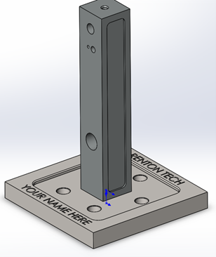
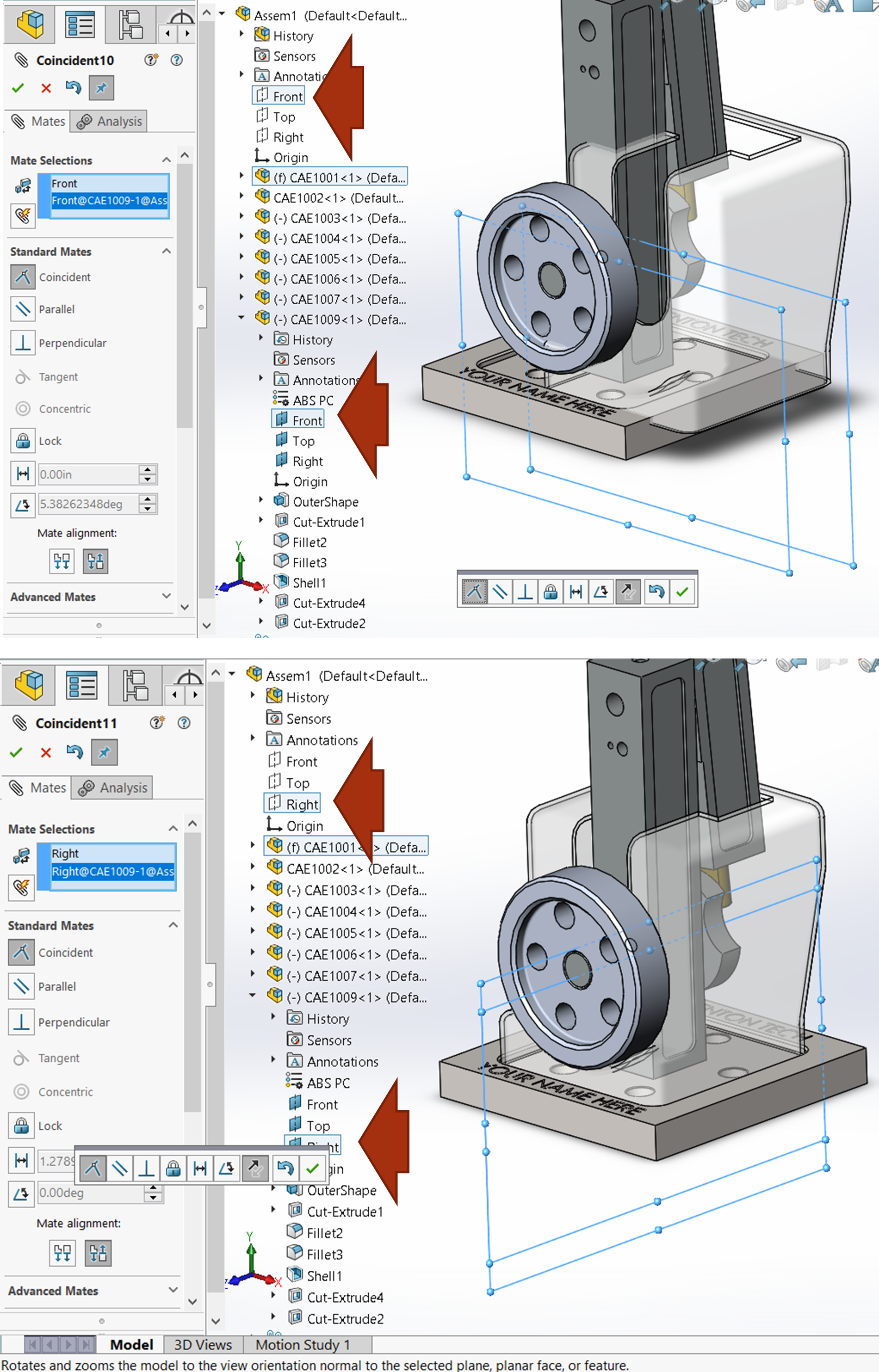
The final design component to insert is CAE1009 using the Insert Components command. Rotate the component into the approximate orientation and add the following mates to CAE1009:
- Coincident mate between the Top Plane of CAE1009 and the Top Pocket Face of CAE1001.
- Coincident mate between the Front Plane of CAE1009 and the Front Plane of the Assembly.
- Coincident mate between the Right Plane of CAE1009 and the Right Plane of the Assembly.

TOOLBOX COMPONENTS
From the task pane on the right side of your screen, click on the Design Library tab. Click on the toolbox. If it is not already loaded in, then load it in.

Navigate to the Hex Head folder by clicking ANSI Inch, Bolts and Screws, Hex Head.
Drag and drop the hex bolt near the left side of the top hole. Set the bolt size to 5/16-18, 3-inch length and 7/8-inch threaded length. Also, choose to show the schematic version of the thread and confirm the property manager for the fastener. For inserting more components, press the red X in the property manager to confirm the command.
Dragging and dropping will sometimes add automatic mates!
Check the mates added if any. We need a concentric mate between the bolt and the left hole locking the rotation and a coincident mate between the left face and the bolt face.

Then navigate to the Plain Washers Type A folder and choose a Preferred Narrow washer to place on the other side of the bolt. Make sure the size matches that of the bolt (5/16) and that you add a concentric and coincident mate locking rotation. Add a second washer, but don’t mate it yet.
The difference between Type A Washers and Type B Washers is that Type B Washers are manufactured to a tighter tolerance.

REMAINING SPRING AND FASTENERS
Insert CAE1008 into the assembly using the Insert Components command. This is the spring that will be flush with the washers and used to apply pressure to the cylinder. This will help prevent locking of the air motor if the cylinder is kept from wiggling during operation.
Apply mates to CAE1008 so that the Top and Right Plane of CAE1008 are coincident with corresponding planes from the hex bolt. Also, apply coincident mates between the end faces of CAE1008 and the corresponding faces on the washers.
Add the two nuts on the end, locking the rotation through the concentric mates.

Add the socket head cap screw on the bottom of the assembly using the design library toolbox. Be sure that there is a concentric mate between the screw and the hole that locks rotation, and a coincident mate between the bottom of the screw head and the bottom of the counterbore.

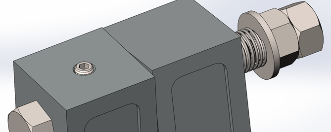
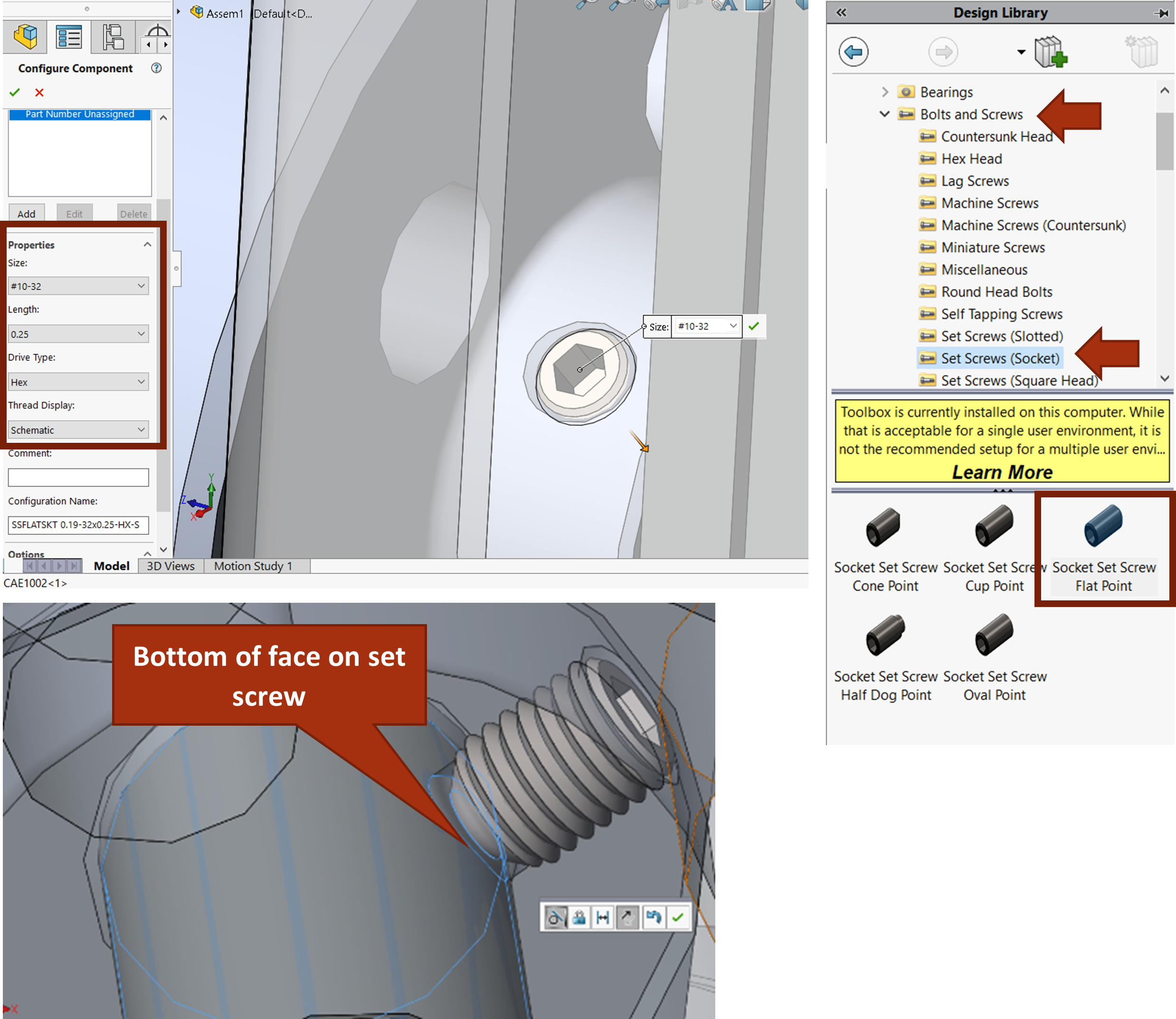
The final thing needed to finish the assembly is adding the two-socket head, flat point set screws on the flywheel and the post. Use the design library toolbox to add a #10-32 by .25” length set screw between CAE1004 and CAE1005 and a #10-32 by .375-inch length set screw between CAE1002 and the hex bolt.
To mate the set screws, add a concentric mate between the cone of their bottom and the threaded hole of the mating component as well as a tangent mate between the flat bottom of the set screw and the shaft the set screw will be digging into.