
4.3: Series Resistor-Capacitor Circuits
- Page ID
- 1403

\( \newcommand{\vecs}[1]{\overset { \scriptstyle \rightharpoonup} {\mathbf{#1}} } \)
\( \newcommand{\vecd}[1]{\overset{-\!-\!\rightharpoonup}{\vphantom{a}\smash {#1}}} \)
\( \newcommand{\id}{\mathrm{id}}\) \( \newcommand{\Span}{\mathrm{span}}\)
( \newcommand{\kernel}{\mathrm{null}\,}\) \( \newcommand{\range}{\mathrm{range}\,}\)
\( \newcommand{\RealPart}{\mathrm{Re}}\) \( \newcommand{\ImaginaryPart}{\mathrm{Im}}\)
\( \newcommand{\Argument}{\mathrm{Arg}}\) \( \newcommand{\norm}[1]{\| #1 \|}\)
\( \newcommand{\inner}[2]{\langle #1, #2 \rangle}\)
\( \newcommand{\Span}{\mathrm{span}}\)
\( \newcommand{\id}{\mathrm{id}}\)
\( \newcommand{\Span}{\mathrm{span}}\)
\( \newcommand{\kernel}{\mathrm{null}\,}\)
\( \newcommand{\range}{\mathrm{range}\,}\)
\( \newcommand{\RealPart}{\mathrm{Re}}\)
\( \newcommand{\ImaginaryPart}{\mathrm{Im}}\)
\( \newcommand{\Argument}{\mathrm{Arg}}\)
\( \newcommand{\norm}[1]{\| #1 \|}\)
\( \newcommand{\inner}[2]{\langle #1, #2 \rangle}\)
\( \newcommand{\Span}{\mathrm{span}}\) \( \newcommand{\AA}{\unicode[.8,0]{x212B}}\)
\( \newcommand{\vectorA}[1]{\vec{#1}} % arrow\)
\( \newcommand{\vectorAt}[1]{\vec{\text{#1}}} % arrow\)
\( \newcommand{\vectorB}[1]{\overset { \scriptstyle \rightharpoonup} {\mathbf{#1}} } \)
\( \newcommand{\vectorC}[1]{\textbf{#1}} \)
\( \newcommand{\vectorD}[1]{\overrightarrow{#1}} \)
\( \newcommand{\vectorDt}[1]{\overrightarrow{\text{#1}}} \)
\( \newcommand{\vectE}[1]{\overset{-\!-\!\rightharpoonup}{\vphantom{a}\smash{\mathbf {#1}}}} \)
\( \newcommand{\vecs}[1]{\overset { \scriptstyle \rightharpoonup} {\mathbf{#1}} } \)
\( \newcommand{\vecd}[1]{\overset{-\!-\!\rightharpoonup}{\vphantom{a}\smash {#1}}} \)
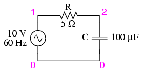
\(\newcommand{\avec}{\mathbf a}\) \(\newcommand{\bvec}{\mathbf b}\) \(\newcommand{\cvec}{\mathbf c}\) \(\newcommand{\dvec}{\mathbf d}\) \(\newcommand{\dtil}{\widetilde{\mathbf d}}\) \(\newcommand{\evec}{\mathbf e}\) \(\newcommand{\fvec}{\mathbf f}\) \(\newcommand{\nvec}{\mathbf n}\) \(\newcommand{\pvec}{\mathbf p}\) \(\newcommand{\qvec}{\mathbf q}\) \(\newcommand{\svec}{\mathbf s}\) \(\newcommand{\tvec}{\mathbf t}\) \(\newcommand{\uvec}{\mathbf u}\) \(\newcommand{\vvec}{\mathbf v}\) \(\newcommand{\wvec}{\mathbf w}\) \(\newcommand{\xvec}{\mathbf x}\) \(\newcommand{\yvec}{\mathbf y}\) \(\newcommand{\zvec}{\mathbf z}\) \(\newcommand{\rvec}{\mathbf r}\) \(\newcommand{\mvec}{\mathbf m}\) \(\newcommand{\zerovec}{\mathbf 0}\) \(\newcommand{\onevec}{\mathbf 1}\) \(\newcommand{\real}{\mathbb R}\) \(\newcommand{\twovec}[2]{\left[\begin{array}{r}#1 \\ #2 \end{array}\right]}\) \(\newcommand{\ctwovec}[2]{\left[\begin{array}{c}#1 \\ #2 \end{array}\right]}\) \(\newcommand{\threevec}[3]{\left[\begin{array}{r}#1 \\ #2 \\ #3 \end{array}\right]}\) \(\newcommand{\cthreevec}[3]{\left[\begin{array}{c}#1 \\ #2 \\ #3 \end{array}\right]}\) \(\newcommand{\fourvec}[4]{\left[\begin{array}{r}#1 \\ #2 \\ #3 \\ #4 \end{array}\right]}\) \(\newcommand{\cfourvec}[4]{\left[\begin{array}{c}#1 \\ #2 \\ #3 \\ #4 \end{array}\right]}\) \(\newcommand{\fivevec}[5]{\left[\begin{array}{r}#1 \\ #2 \\ #3 \\ #4 \\ #5 \\ \end{array}\right]}\) \(\newcommand{\cfivevec}[5]{\left[\begin{array}{c}#1 \\ #2 \\ #3 \\ #4 \\ #5 \\ \end{array}\right]}\) \(\newcommand{\mattwo}[4]{\left[\begin{array}{rr}#1 \amp #2 \\ #3 \amp #4 \\ \end{array}\right]}\) \(\newcommand{\laspan}[1]{\text{Span}\{#1\}}\) \(\newcommand{\bcal}{\cal B}\) \(\newcommand{\ccal}{\cal C}\) \(\newcommand{\scal}{\cal S}\) \(\newcommand{\wcal}{\cal W}\) \(\newcommand{\ecal}{\cal E}\) \(\newcommand{\coords}[2]{\left\{#1\right\}_{#2}}\) \(\newcommand{\gray}[1]{\color{gray}{#1}}\) \(\newcommand{\lgray}[1]{\color{lightgray}{#1}}\) \(\newcommand{\rank}{\operatorname{rank}}\) \(\newcommand{\row}{\text{Row}}\) \(\newcommand{\col}{\text{Col}}\) \(\renewcommand{\row}{\text{Row}}\) \(\newcommand{\nul}{\text{Nul}}\) \(\newcommand{\var}{\text{Var}}\) \(\newcommand{\corr}{\text{corr}}\) \(\newcommand{\len}[1]{\left|#1\right|}\) \(\newcommand{\bbar}{\overline{\bvec}}\) \(\newcommand{\bhat}{\widehat{\bvec}}\) \(\newcommand{\bperp}{\bvec^\perp}\) \(\newcommand{\xhat}{\widehat{\xvec}}\) \(\newcommand{\vhat}{\widehat{\vvec}}\) \(\newcommand{\uhat}{\widehat{\uvec}}\) \(\newcommand{\what}{\widehat{\wvec}}\) \(\newcommand{\Sighat}{\widehat{\Sigma}}\) \(\newcommand{\lt}{<}\) \(\newcommand{\gt}{>}\) \(\newcommand{\amp}{&}\) \(\definecolor{fillinmathshade}{gray}{0.9}\)In the last section, we learned what would happen in simple resistor-only and capacitor-only AC circuits. Now we will combine the two components together in series form and investigate the effects. (Figure below)
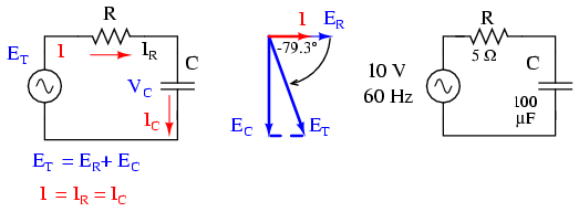
Series capacitor circuit: voltage lags current by 0o to 90o.
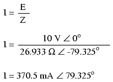
The resistor will offer 5 Ω of resistance to AC current regardless of frequency, while the capacitor will offer 26.5258 Ω of reactance to AC current at 60 Hz. Because the resistor’s resistance is a real number (5 Ω ∠ 0o, or 5 + j0 Ω), and the capacitor’s reactance is an imaginary number (26.5258 Ω ∠ -90o, or 0 - j26.5258 Ω), the combined effect of the two components will be an opposition to current equal to the complex sum of the two numbers. The term for this complex opposition to current is impedance, its symbol is Z, and it is also expressed in the unit of ohms, just like resistance and reactance. In the above example, the total circuit impedance is:
Impedance is related to voltage and current just as you might expect, in a manner similar to resistance in Ohm’s Law:
.webp?revision=1)
In fact, this is a far more comprehensive form of Ohm’s Law than what was taught in DC electronics (E=IR), just as impedance is a far more comprehensive expression of opposition to the flow of electrons than simple resistance is. Any resistance and any reactance, separately or in combination (series/parallel), can be and should be represented as a single impedance.
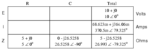
To calculate current in the above circuit, we first need to give a phase angle reference for the voltage source, which is generally assumed to be zero. (The phase angles of resistive and capacitive impedance are always 0o and -90o, respectively, regardless of the given phase angles for voltage or current).
As with the purely capacitive circuit, the current wave is leading the voltage wave (of the source), although this time the difference is 79.325o instead of a full 90o. (Figure below)
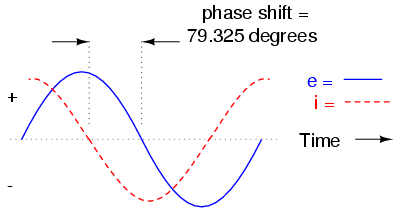
Voltage lags current (current leads voltage)in a series R-C circuit.
As we learned in the AC inductance chapter, the “table” method of organizing circuit quantities is a very useful tool for AC analysis just as it is for DC analysis. Let’s place out known figures for this series circuit into a table and continue the analysis using this tool:
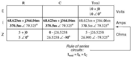
Current in a series circuit is shared equally by all components, so the figures placed in the “Total” column for current can be distributed to all other columns as well:
Continuing with our analysis, we can apply Ohm’s Law (E=IR) vertically to determine voltage across the resistor and capacitor:
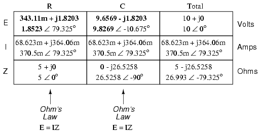
Notice how the voltage across the resistor has the exact same phase angle as the current through it, telling us that E and I are in phase (for the resistor only). The voltage across the capacitor has a phase angle of -10.675o, exactly 90o less than the phase angle of the circuit current. This tells us that the capacitor’s voltage and current are still 90o out of phase with each other.
Let’s check our calculations with SPICE: (Figure below)
Spice circuit: R-C.
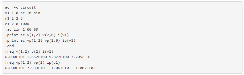
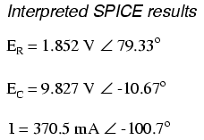
Once again, SPICE confusingly prints the current phase angle at a value equal to the real phase angle plus 180o (or minus 180o). However, its a simple matter to correct this figure and check to see if our work is correct. In this case, the -100.7o output by SPICE for current phase angle equates to a positive 79.3o, which does correspond to our previously calculated figure of 79.325o.
Again, it must be emphasized that the calculated figures corresponding to real-life voltage and current measurements are those in polar form, not rectangular form! For example, if we were to actually build this series resistor-capacitor circuit and measure voltage across the resistor, our voltmeter would indicate 1.8523 volts, not 343.11 millivolts (real rectangular) or 1.8203 volts (imaginary rectangular). Real instruments connected to real circuits provide indications corresponding to the vector length (magnitude) of the calculated figures. While the rectangular form of complex number notation is useful for performing addition and subtraction, it is a more abstract form of notation than polar, which alone has direct correspondence to true measurements.
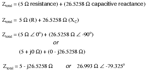
Impedance (Z) of a series R-C circuit may be calculated, given the resistance (R) and the capacitive reactance (XC). Since E=IR, E=IXC, and E=IZ, resistance, reactance, and impedance are proportional to voltage, respectively. Thus, the voltage phasor diagram can be replaced by a similar impedance diagram. (Figure below)
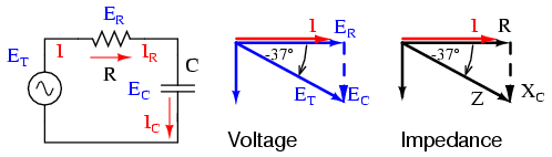
Series: R-C circuit Impedance phasor diagram.
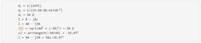
Example:
Given: A 40 Ω resistor in series with a 88.42 microfarad capacitor. Find the impedance at 60 hertz.
Review
- Impedance is the total measure of opposition to electric current and is the complex (vector) sum of (“real”) resistance and (“imaginary”) reactance.
- Impedances (Z) are managed just like resistances (R) in series circuit analysis: series impedances add to form the total impedance. Just be sure to perform all calculations in complex (not scalar) form! ZTotal = Z1 + Z2 + . . . Zn
- Please note that impedances always add in series, regardless of what type of components comprise the impedances. That is, resistive impedance, inductive impedance, and capacitive impedance are to be treated the same way mathematically.
- A purely resistive impedance will always have a phase angle of exactly 0o (ZR = R Ω ∠ 0o).
- A purely capacitive impedance will always have a phase angle of exactly -90o (ZC = XC Ω ∠ -90o).
- Ohm’s Law for AC circuits: E = IZ ; I = E/Z ; Z = E/I
- When resistors and capacitors are mixed together in circuits, the total impedance will have a phase angle somewhere between 0o and -90o.