1.7: Sectional Views
- Page ID
- 5188

\( \newcommand{\vecs}[1]{\overset { \scriptstyle \rightharpoonup} {\mathbf{#1}} } \)
\( \newcommand{\vecd}[1]{\overset{-\!-\!\rightharpoonup}{\vphantom{a}\smash {#1}}} \)
\( \newcommand{\dsum}{\displaystyle\sum\limits} \)
\( \newcommand{\dint}{\displaystyle\int\limits} \)
\( \newcommand{\dlim}{\displaystyle\lim\limits} \)
\( \newcommand{\id}{\mathrm{id}}\) \( \newcommand{\Span}{\mathrm{span}}\)
( \newcommand{\kernel}{\mathrm{null}\,}\) \( \newcommand{\range}{\mathrm{range}\,}\)
\( \newcommand{\RealPart}{\mathrm{Re}}\) \( \newcommand{\ImaginaryPart}{\mathrm{Im}}\)
\( \newcommand{\Argument}{\mathrm{Arg}}\) \( \newcommand{\norm}[1]{\| #1 \|}\)
\( \newcommand{\inner}[2]{\langle #1, #2 \rangle}\)
\( \newcommand{\Span}{\mathrm{span}}\)
\( \newcommand{\id}{\mathrm{id}}\)
\( \newcommand{\Span}{\mathrm{span}}\)
\( \newcommand{\kernel}{\mathrm{null}\,}\)
\( \newcommand{\range}{\mathrm{range}\,}\)
\( \newcommand{\RealPart}{\mathrm{Re}}\)
\( \newcommand{\ImaginaryPart}{\mathrm{Im}}\)
\( \newcommand{\Argument}{\mathrm{Arg}}\)
\( \newcommand{\norm}[1]{\| #1 \|}\)
\( \newcommand{\inner}[2]{\langle #1, #2 \rangle}\)
\( \newcommand{\Span}{\mathrm{span}}\) \( \newcommand{\AA}{\unicode[.8,0]{x212B}}\)
\( \newcommand{\vectorA}[1]{\vec{#1}} % arrow\)
\( \newcommand{\vectorAt}[1]{\vec{\text{#1}}} % arrow\)
\( \newcommand{\vectorB}[1]{\overset { \scriptstyle \rightharpoonup} {\mathbf{#1}} } \)
\( \newcommand{\vectorC}[1]{\textbf{#1}} \)
\( \newcommand{\vectorD}[1]{\overrightarrow{#1}} \)
\( \newcommand{\vectorDt}[1]{\overrightarrow{\text{#1}}} \)
\( \newcommand{\vectE}[1]{\overset{-\!-\!\rightharpoonup}{\vphantom{a}\smash{\mathbf {#1}}}} \)
\( \newcommand{\vecs}[1]{\overset { \scriptstyle \rightharpoonup} {\mathbf{#1}} } \)
\(\newcommand{\longvect}{\overrightarrow}\)
\( \newcommand{\vecd}[1]{\overset{-\!-\!\rightharpoonup}{\vphantom{a}\smash {#1}}} \)
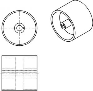
\(\newcommand{\avec}{\mathbf a}\) \(\newcommand{\bvec}{\mathbf b}\) \(\newcommand{\cvec}{\mathbf c}\) \(\newcommand{\dvec}{\mathbf d}\) \(\newcommand{\dtil}{\widetilde{\mathbf d}}\) \(\newcommand{\evec}{\mathbf e}\) \(\newcommand{\fvec}{\mathbf f}\) \(\newcommand{\nvec}{\mathbf n}\) \(\newcommand{\pvec}{\mathbf p}\) \(\newcommand{\qvec}{\mathbf q}\) \(\newcommand{\svec}{\mathbf s}\) \(\newcommand{\tvec}{\mathbf t}\) \(\newcommand{\uvec}{\mathbf u}\) \(\newcommand{\vvec}{\mathbf v}\) \(\newcommand{\wvec}{\mathbf w}\) \(\newcommand{\xvec}{\mathbf x}\) \(\newcommand{\yvec}{\mathbf y}\) \(\newcommand{\zvec}{\mathbf z}\) \(\newcommand{\rvec}{\mathbf r}\) \(\newcommand{\mvec}{\mathbf m}\) \(\newcommand{\zerovec}{\mathbf 0}\) \(\newcommand{\onevec}{\mathbf 1}\) \(\newcommand{\real}{\mathbb R}\) \(\newcommand{\twovec}[2]{\left[\begin{array}{r}#1 \\ #2 \end{array}\right]}\) \(\newcommand{\ctwovec}[2]{\left[\begin{array}{c}#1 \\ #2 \end{array}\right]}\) \(\newcommand{\threevec}[3]{\left[\begin{array}{r}#1 \\ #2 \\ #3 \end{array}\right]}\) \(\newcommand{\cthreevec}[3]{\left[\begin{array}{c}#1 \\ #2 \\ #3 \end{array}\right]}\) \(\newcommand{\fourvec}[4]{\left[\begin{array}{r}#1 \\ #2 \\ #3 \\ #4 \end{array}\right]}\) \(\newcommand{\cfourvec}[4]{\left[\begin{array}{c}#1 \\ #2 \\ #3 \\ #4 \end{array}\right]}\) \(\newcommand{\fivevec}[5]{\left[\begin{array}{r}#1 \\ #2 \\ #3 \\ #4 \\ #5 \\ \end{array}\right]}\) \(\newcommand{\cfivevec}[5]{\left[\begin{array}{c}#1 \\ #2 \\ #3 \\ #4 \\ #5 \\ \end{array}\right]}\) \(\newcommand{\mattwo}[4]{\left[\begin{array}{rr}#1 \amp #2 \\ #3 \amp #4 \\ \end{array}\right]}\) \(\newcommand{\laspan}[1]{\text{Span}\{#1\}}\) \(\newcommand{\bcal}{\cal B}\) \(\newcommand{\ccal}{\cal C}\) \(\newcommand{\scal}{\cal S}\) \(\newcommand{\wcal}{\cal W}\) \(\newcommand{\ecal}{\cal E}\) \(\newcommand{\coords}[2]{\left\{#1\right\}_{#2}}\) \(\newcommand{\gray}[1]{\color{gray}{#1}}\) \(\newcommand{\lgray}[1]{\color{lightgray}{#1}}\) \(\newcommand{\rank}{\operatorname{rank}}\) \(\newcommand{\row}{\text{Row}}\) \(\newcommand{\col}{\text{Col}}\) \(\renewcommand{\row}{\text{Row}}\) \(\newcommand{\nul}{\text{Nul}}\) \(\newcommand{\var}{\text{Var}}\) \(\newcommand{\corr}{\text{corr}}\) \(\newcommand{\len}[1]{\left|#1\right|}\) \(\newcommand{\bbar}{\overline{\bvec}}\) \(\newcommand{\bhat}{\widehat{\bvec}}\) \(\newcommand{\bperp}{\bvec^\perp}\) \(\newcommand{\xhat}{\widehat{\xvec}}\) \(\newcommand{\vhat}{\widehat{\vvec}}\) \(\newcommand{\uhat}{\widehat{\uvec}}\) \(\newcommand{\what}{\widehat{\wvec}}\) \(\newcommand{\Sighat}{\widehat{\Sigma}}\) \(\newcommand{\lt}{<}\) \(\newcommand{\gt}{>}\) \(\newcommand{\amp}{&}\) \(\definecolor{fillinmathshade}{gray}{0.9}\)You have learned that when making a multiview sketch, hidden edges and surfaces are usually shown with hidden (dash) lines.
When an object becomes more complex, as in the case of an automobile engine block, a clearer presentation of the interior can be made by sketching the object as it would look if it were cut apart. In that way, the many hidden lines on the sketch are eliminated.
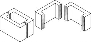
The process of sketching the internal configuration of an object by showing it cut apart is known as sectioning. Sectioning is used frequently on a wide variety of Industrial drawings.
In this example, blocks A and B result after the block in figure 1 has been “Sectioned”. When you cut an apple in half you have sectioned it. Just as an apple can be sectioned any way you choose, so can an object in a sectional view of a drawing or sketch.
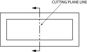
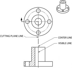
Cutting Plane
A surface cut by the saw in the drawing above is a cutting plane. Actually, it is an imaginary cutting plane taken through the object, since the object is imagined as being cut through at a desired location.
Cutting Plane Line
A cutting plane is represented on a drawing by a cutting plane line. This is a heavy long-short-short-long kind of line terminated with arrows. The arrows in show the direction of view.
Once again, here is an graphic example of a cutting plane line and the section that develops from it.
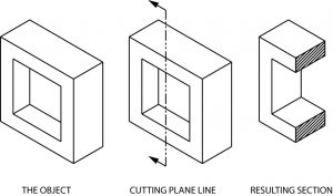
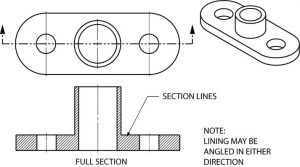
Section Lining
The lines in the figure above, which look like saw marks, are called section lining. They are found on most sectional views, and indicate the surface which has been exposed by the cutting plane. Notice that the square hole in the object has no section lining, since it was not changed by sectioning.
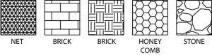
Different kinds of section lining is used to identify different materials. When an object is made of a combination of materials, a variety of section lining symbols makes materials identification easier. Here are a few examples:
Section lines are very light. When sketching an object or part that requires a sectional view, they are drawn by eye at an angle of approximately 45 degrees, and are spaced about 1/8” apart. Since they are used to set off a section, they must be drawn with care.
It is best to use the symbol for the material being shown as a section on a sketch. If that symbol is not known, you may use the general purpose symbol, which is also the symbol for cast iron.
Full Sections
When a cutting plane line passes entirely through an object, the resulting section is called a full section Fig. 7 illustrates a full section.
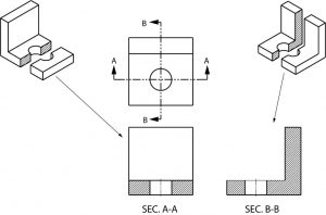
It is possible to section an object whenever a closer look intentionally is desired. Here is an object sectioned from two different directions.
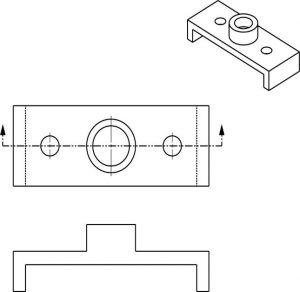
Half Sections
If the cutting plane is passed halfway through an object, and one-quarter of the object is removed, the resulting section is a half section. A half section has the advantage of showing both inside and outside configurations.
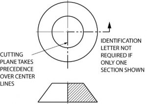
It is frequently used for symmetrical objects. Hidden lines are usually not shown on the un-sectioned half unless they are needed for clearness or for dimensioning purposes. As in all sectional drawings, the cutting plane take precedence over the center line.
Here is another example of a half section. Remember that only one fourth of the object is removed with a half section, whereas half of the object is generally removed with a full section.
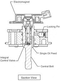
This manufacturer’s drawing, using both full and half section, illustrates the advantages of sectional views. The different line directions indicate different parts and materials used in the assembly of this valve.
Quiz
Directions: On a separate sheet of paper, complete the section view.
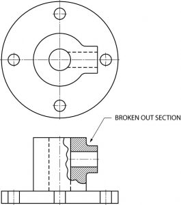
Broken Out Sections
In many cases only a small part of a view needs to be sectioned in order to show some internal detail. In the figure below, the broken out section is removed by a freehand break line. A cutting plane line does not need to be shown, since the location of the cut is obvious.
Revolved Sections
A revolved section shows the shape of an object by rotating a section 90 degrees to face the viewer. The three revolved sections illustrated in the spear-like object of figure 12 show the changes that take place in its shape.

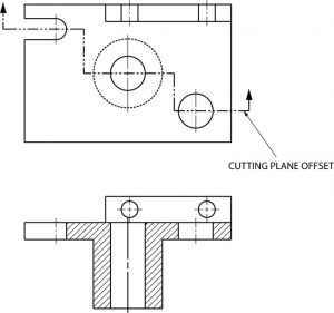
Offset Sections
An offset section is a means of including in a single section several features of an object that are not in a straight line. To do this, the cutting plane line is bent, or “OFFSET” to pass through the features of the part.
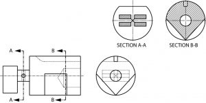
Removed Sections
A section removed from its normal projected position in the standard arrangement of views is called a “removed” section. Such sections are labeled SECTION A-A, SECTION B-B, etc., corresponding to the letter designation at the ends of the cutting plane line. Removed sections may be partial sections and are often drawn to a different scale.
Quiz
Directions: Complete the half section view of a separate sheet of paper.