1.8: Plug Weld symbols
- Page ID
- 5154
\( \newcommand{\vecs}[1]{\overset { \scriptstyle \rightharpoonup} {\mathbf{#1}} } \)
\( \newcommand{\vecd}[1]{\overset{-\!-\!\rightharpoonup}{\vphantom{a}\smash {#1}}} \)
\( \newcommand{\id}{\mathrm{id}}\) \( \newcommand{\Span}{\mathrm{span}}\)
( \newcommand{\kernel}{\mathrm{null}\,}\) \( \newcommand{\range}{\mathrm{range}\,}\)
\( \newcommand{\RealPart}{\mathrm{Re}}\) \( \newcommand{\ImaginaryPart}{\mathrm{Im}}\)
\( \newcommand{\Argument}{\mathrm{Arg}}\) \( \newcommand{\norm}[1]{\| #1 \|}\)
\( \newcommand{\inner}[2]{\langle #1, #2 \rangle}\)
\( \newcommand{\Span}{\mathrm{span}}\)
\( \newcommand{\id}{\mathrm{id}}\)
\( \newcommand{\Span}{\mathrm{span}}\)
\( \newcommand{\kernel}{\mathrm{null}\,}\)
\( \newcommand{\range}{\mathrm{range}\,}\)
\( \newcommand{\RealPart}{\mathrm{Re}}\)
\( \newcommand{\ImaginaryPart}{\mathrm{Im}}\)
\( \newcommand{\Argument}{\mathrm{Arg}}\)
\( \newcommand{\norm}[1]{\| #1 \|}\)
\( \newcommand{\inner}[2]{\langle #1, #2 \rangle}\)
\( \newcommand{\Span}{\mathrm{span}}\) \( \newcommand{\AA}{\unicode[.8,0]{x212B}}\)
\( \newcommand{\vectorA}[1]{\vec{#1}} % arrow\)
\( \newcommand{\vectorAt}[1]{\vec{\text{#1}}} % arrow\)
\( \newcommand{\vectorB}[1]{\overset { \scriptstyle \rightharpoonup} {\mathbf{#1}} } \)
\( \newcommand{\vectorC}[1]{\textbf{#1}} \)
\( \newcommand{\vectorD}[1]{\overrightarrow{#1}} \)
\( \newcommand{\vectorDt}[1]{\overrightarrow{\text{#1}}} \)
\( \newcommand{\vectE}[1]{\overset{-\!-\!\rightharpoonup}{\vphantom{a}\smash{\mathbf {#1}}}} \)
\( \newcommand{\vecs}[1]{\overset { \scriptstyle \rightharpoonup} {\mathbf{#1}} } \)
\( \newcommand{\vecd}[1]{\overset{-\!-\!\rightharpoonup}{\vphantom{a}\smash {#1}}} \)
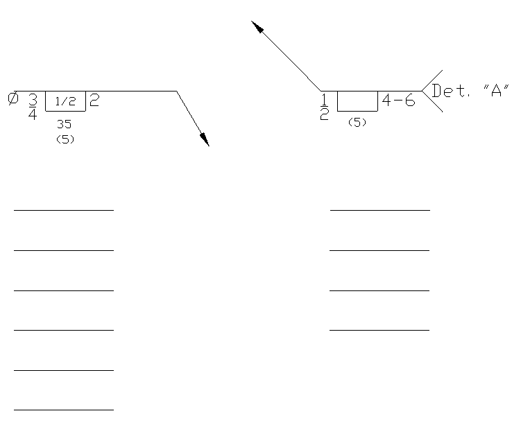
\(\newcommand{\avec}{\mathbf a}\) \(\newcommand{\bvec}{\mathbf b}\) \(\newcommand{\cvec}{\mathbf c}\) \(\newcommand{\dvec}{\mathbf d}\) \(\newcommand{\dtil}{\widetilde{\mathbf d}}\) \(\newcommand{\evec}{\mathbf e}\) \(\newcommand{\fvec}{\mathbf f}\) \(\newcommand{\nvec}{\mathbf n}\) \(\newcommand{\pvec}{\mathbf p}\) \(\newcommand{\qvec}{\mathbf q}\) \(\newcommand{\svec}{\mathbf s}\) \(\newcommand{\tvec}{\mathbf t}\) \(\newcommand{\uvec}{\mathbf u}\) \(\newcommand{\vvec}{\mathbf v}\) \(\newcommand{\wvec}{\mathbf w}\) \(\newcommand{\xvec}{\mathbf x}\) \(\newcommand{\yvec}{\mathbf y}\) \(\newcommand{\zvec}{\mathbf z}\) \(\newcommand{\rvec}{\mathbf r}\) \(\newcommand{\mvec}{\mathbf m}\) \(\newcommand{\zerovec}{\mathbf 0}\) \(\newcommand{\onevec}{\mathbf 1}\) \(\newcommand{\real}{\mathbb R}\) \(\newcommand{\twovec}[2]{\left[\begin{array}{r}#1 \\ #2 \end{array}\right]}\) \(\newcommand{\ctwovec}[2]{\left[\begin{array}{c}#1 \\ #2 \end{array}\right]}\) \(\newcommand{\threevec}[3]{\left[\begin{array}{r}#1 \\ #2 \\ #3 \end{array}\right]}\) \(\newcommand{\cthreevec}[3]{\left[\begin{array}{c}#1 \\ #2 \\ #3 \end{array}\right]}\) \(\newcommand{\fourvec}[4]{\left[\begin{array}{r}#1 \\ #2 \\ #3 \\ #4 \end{array}\right]}\) \(\newcommand{\cfourvec}[4]{\left[\begin{array}{c}#1 \\ #2 \\ #3 \\ #4 \end{array}\right]}\) \(\newcommand{\fivevec}[5]{\left[\begin{array}{r}#1 \\ #2 \\ #3 \\ #4 \\ #5 \\ \end{array}\right]}\) \(\newcommand{\cfivevec}[5]{\left[\begin{array}{c}#1 \\ #2 \\ #3 \\ #4 \\ #5 \\ \end{array}\right]}\) \(\newcommand{\mattwo}[4]{\left[\begin{array}{rr}#1 \amp #2 \\ #3 \amp #4 \\ \end{array}\right]}\) \(\newcommand{\laspan}[1]{\text{Span}\{#1\}}\) \(\newcommand{\bcal}{\cal B}\) \(\newcommand{\ccal}{\cal C}\) \(\newcommand{\scal}{\cal S}\) \(\newcommand{\wcal}{\cal W}\) \(\newcommand{\ecal}{\cal E}\) \(\newcommand{\coords}[2]{\left\{#1\right\}_{#2}}\) \(\newcommand{\gray}[1]{\color{gray}{#1}}\) \(\newcommand{\lgray}[1]{\color{lightgray}{#1}}\) \(\newcommand{\rank}{\operatorname{rank}}\) \(\newcommand{\row}{\text{Row}}\) \(\newcommand{\col}{\text{Col}}\) \(\renewcommand{\row}{\text{Row}}\) \(\newcommand{\nul}{\text{Nul}}\) \(\newcommand{\var}{\text{Var}}\) \(\newcommand{\corr}{\text{corr}}\) \(\newcommand{\len}[1]{\left|#1\right|}\) \(\newcommand{\bbar}{\overline{\bvec}}\) \(\newcommand{\bhat}{\widehat{\bvec}}\) \(\newcommand{\bperp}{\bvec^\perp}\) \(\newcommand{\xhat}{\widehat{\xvec}}\) \(\newcommand{\vhat}{\widehat{\vvec}}\) \(\newcommand{\uhat}{\widehat{\uvec}}\) \(\newcommand{\what}{\widehat{\wvec}}\) \(\newcommand{\Sighat}{\widehat{\Sigma}}\) \(\newcommand{\lt}{<}\) \(\newcommand{\gt}{>}\) \(\newcommand{\amp}{&}\) \(\definecolor{fillinmathshade}{gray}{0.9}\)Plug welds are a round weld that is made inside of an existing hole most commonly in one piece of metal, welding that piece to another member. The plug weld symbol is a rectangle with a diameter symbol placed to the left of the symbol as well as the number associated with that diameter.
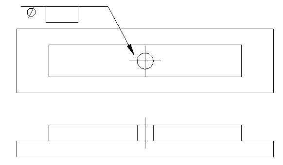
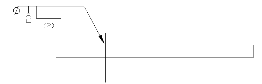
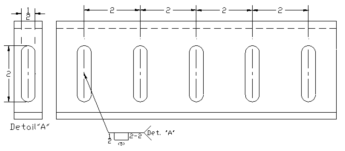
Some drawings will not indicate the hole in the print so the use of dimensions come in to play when locating where a plug weld will be executed. The location will be indicated by a centerline through the part.
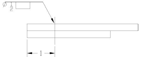
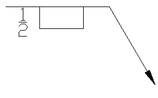
Above is indicating a ½” plug weld offset 1” from the edge to the center of the weld.
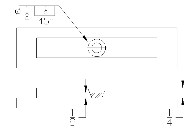
Some plug welds may include a countersink of the hole of the plug weld. This is called the included angle of countersink. This angle is shown below the rectangle of the symbol itself or if the plug weld is to be on the other side it will be placed above the weld symbol. When figuring sizing of the hole remember that the diameter will be the narrow of the hole at the base of the weld.
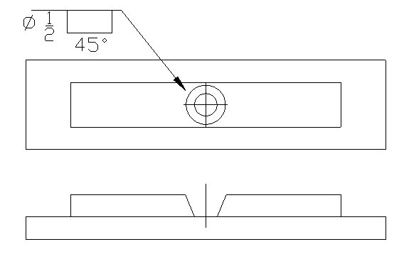
Without a countersink included it will be necessary to follow shop standards and procedures to dictate what this needs to be, if any angle. Most shops have a procedure in place for tasks that will be done often. If it is needed it may be listed on a welding procedure for the plug welds that are being completed.
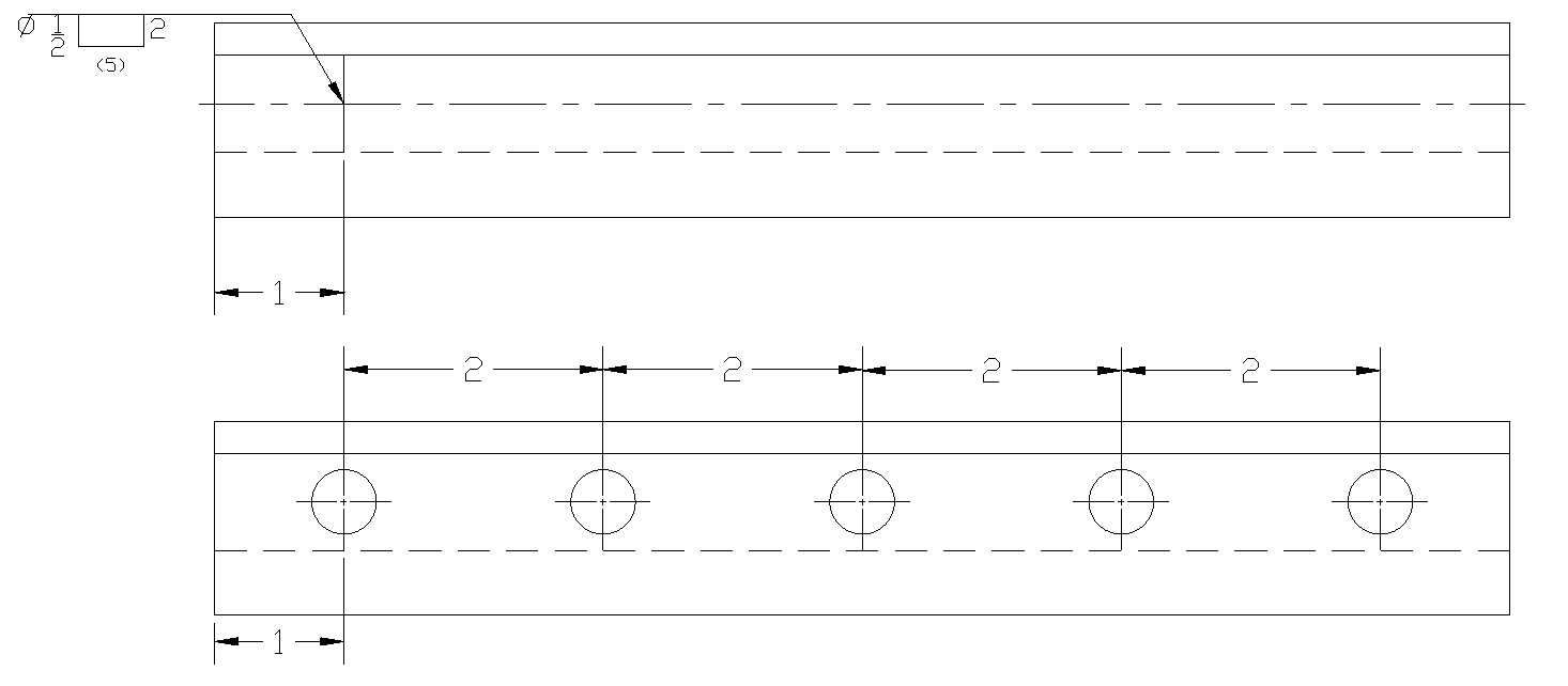
If a number of plug welds are needed there will be yet another element added to the symbol. This will be a number that is surrounded in parentheses, such as (6) for example.
When applying a plug weld it is important to know the depth of fill that is required. If the plug weld should fill the hole provided then the symbol will be left empty. This means there will be no dimension inside of the rectangle. If the hole should be filled only so much then this will be placed inside of the rectangle. This dimension will be in a fraction and indicates the amount in inches the hole will be filled, not the necessarily how much the hole will be filled.
Another element that can be added to this weld symbol may be the pitch (spacing) for multiple welds. This is located to the right of the symbol and is a number representing the center to center spacing for weld location.
Plug welds may have a contour symbol which will be added below the symbol or countersink angle if on the arrow side and above if it is on the other side of the reference line. There are many types of contours and finishing designations, these are covered in supplementary welding symbols.
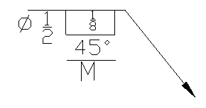
This symbol represents:
Plug Weld
Arrow Side
½ inch in diameter
1/8” amount of fill
45 degree included angle of countersink
Flat contour
Finished by Machining
Slot Weld Symbol
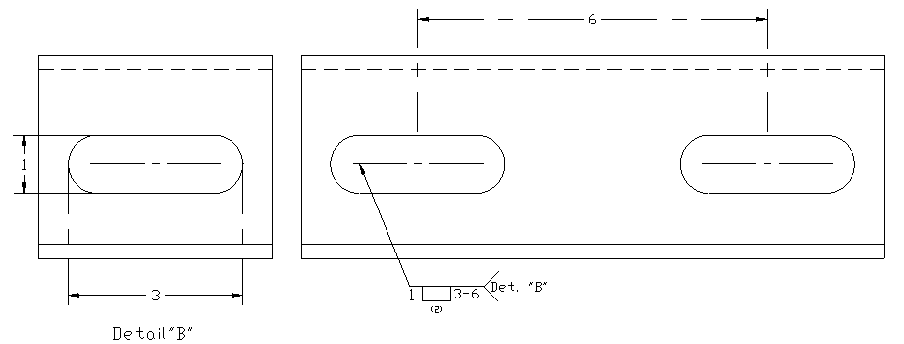
The slot weld symbol is the same that is used for plug welds. The symbol will not show a diameter symbol before the size however. The size of the weld will be the slot width instead. This is shown to the left of the symbol just as it is shown in plug welds.
 1/2” width slot weld
The length of the slot weld will be presented to the right of the symbol. This may also include a pitch showing the center to center spacing of the slot welds. If there is a pitch there will be a number of slot welds provided in parenthesis under the symbol on the arrow side or above the symbol on an other side weld.
The drawing must show the orientation of the slot welds as to not confuse direction along the part. The above image shows the slots with a vertical orientation to the part versus a horizontal layout as shown below.
A slot weld can include any number of elements, these are very similar to the plug weld symbol that was just explained.
These can include:
Arrow or other side
Size (width)
Length of slot
Pitch
Depth of fill
Number of welds required
Contour
Finish
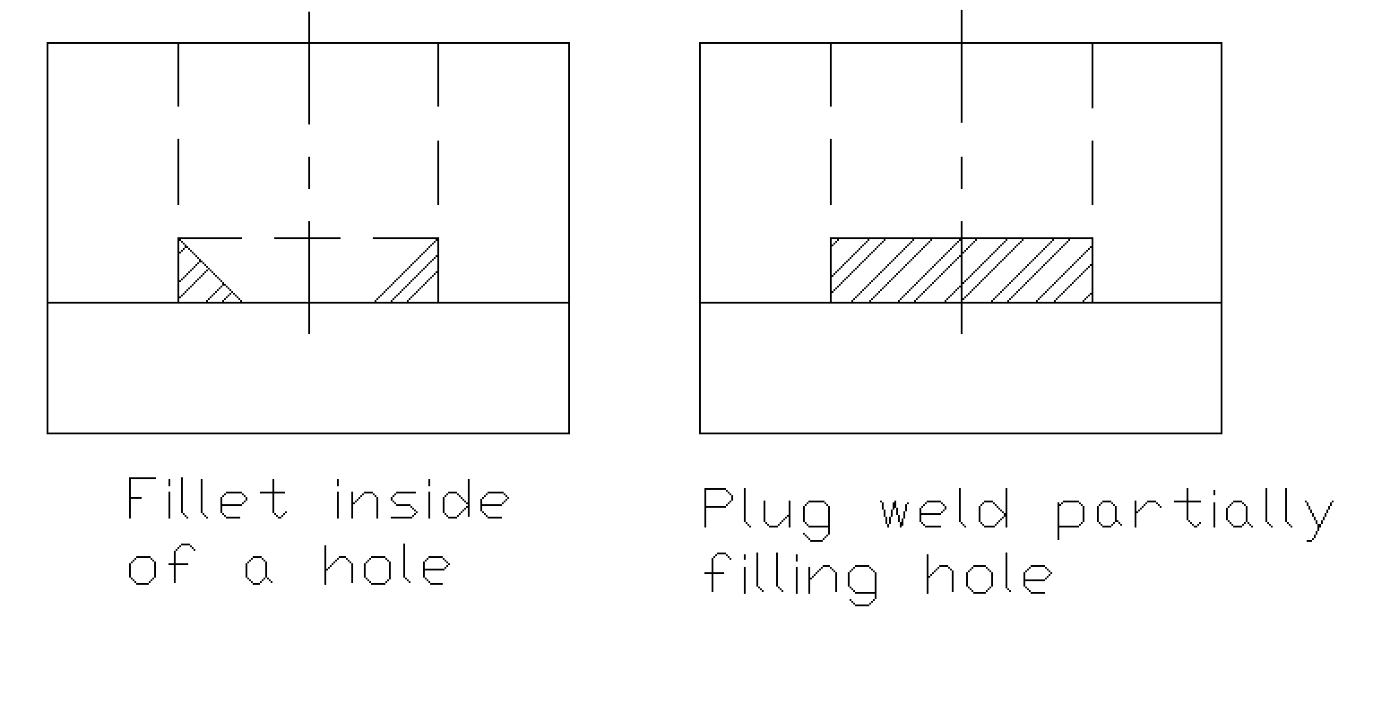
Make no mistake on the fill of a plug or slot weld fill. There is a possibility of having a fillet weld inside of a hole versus actually filling the hole for a plug weld. This could also be mistakenly done on a slot weld.
Plug and Slot Quiz
Write down all information regarding the below Welding Symbols.