
11.4: Lateral Design
- Page ID
- 44633
\( \newcommand{\vecs}[1]{\overset { \scriptstyle \rightharpoonup} {\mathbf{#1}} } \)
\( \newcommand{\vecd}[1]{\overset{-\!-\!\rightharpoonup}{\vphantom{a}\smash {#1}}} \)
\( \newcommand{\dsum}{\displaystyle\sum\limits} \)
\( \newcommand{\dint}{\displaystyle\int\limits} \)
\( \newcommand{\dlim}{\displaystyle\lim\limits} \)
\( \newcommand{\id}{\mathrm{id}}\) \( \newcommand{\Span}{\mathrm{span}}\)
( \newcommand{\kernel}{\mathrm{null}\,}\) \( \newcommand{\range}{\mathrm{range}\,}\)
\( \newcommand{\RealPart}{\mathrm{Re}}\) \( \newcommand{\ImaginaryPart}{\mathrm{Im}}\)
\( \newcommand{\Argument}{\mathrm{Arg}}\) \( \newcommand{\norm}[1]{\| #1 \|}\)
\( \newcommand{\inner}[2]{\langle #1, #2 \rangle}\)
\( \newcommand{\Span}{\mathrm{span}}\)
\( \newcommand{\id}{\mathrm{id}}\)
\( \newcommand{\Span}{\mathrm{span}}\)
\( \newcommand{\kernel}{\mathrm{null}\,}\)
\( \newcommand{\range}{\mathrm{range}\,}\)
\( \newcommand{\RealPart}{\mathrm{Re}}\)
\( \newcommand{\ImaginaryPart}{\mathrm{Im}}\)
\( \newcommand{\Argument}{\mathrm{Arg}}\)
\( \newcommand{\norm}[1]{\| #1 \|}\)
\( \newcommand{\inner}[2]{\langle #1, #2 \rangle}\)
\( \newcommand{\Span}{\mathrm{span}}\) \( \newcommand{\AA}{\unicode[.8,0]{x212B}}\)
\( \newcommand{\vectorA}[1]{\vec{#1}} % arrow\)
\( \newcommand{\vectorAt}[1]{\vec{\text{#1}}} % arrow\)
\( \newcommand{\vectorB}[1]{\overset { \scriptstyle \rightharpoonup} {\mathbf{#1}} } \)
\( \newcommand{\vectorC}[1]{\textbf{#1}} \)
\( \newcommand{\vectorD}[1]{\overrightarrow{#1}} \)
\( \newcommand{\vectorDt}[1]{\overrightarrow{\text{#1}}} \)
\( \newcommand{\vectE}[1]{\overset{-\!-\!\rightharpoonup}{\vphantom{a}\smash{\mathbf {#1}}}} \)
\( \newcommand{\vecs}[1]{\overset { \scriptstyle \rightharpoonup} {\mathbf{#1}} } \)
\(\newcommand{\longvect}{\overrightarrow}\)
\( \newcommand{\vecd}[1]{\overset{-\!-\!\rightharpoonup}{\vphantom{a}\smash {#1}}} \)
\(\newcommand{\avec}{\mathbf a}\) \(\newcommand{\bvec}{\mathbf b}\) \(\newcommand{\cvec}{\mathbf c}\) \(\newcommand{\dvec}{\mathbf d}\) \(\newcommand{\dtil}{\widetilde{\mathbf d}}\) \(\newcommand{\evec}{\mathbf e}\) \(\newcommand{\fvec}{\mathbf f}\) \(\newcommand{\nvec}{\mathbf n}\) \(\newcommand{\pvec}{\mathbf p}\) \(\newcommand{\qvec}{\mathbf q}\) \(\newcommand{\svec}{\mathbf s}\) \(\newcommand{\tvec}{\mathbf t}\) \(\newcommand{\uvec}{\mathbf u}\) \(\newcommand{\vvec}{\mathbf v}\) \(\newcommand{\wvec}{\mathbf w}\) \(\newcommand{\xvec}{\mathbf x}\) \(\newcommand{\yvec}{\mathbf y}\) \(\newcommand{\zvec}{\mathbf z}\) \(\newcommand{\rvec}{\mathbf r}\) \(\newcommand{\mvec}{\mathbf m}\) \(\newcommand{\zerovec}{\mathbf 0}\) \(\newcommand{\onevec}{\mathbf 1}\) \(\newcommand{\real}{\mathbb R}\) \(\newcommand{\twovec}[2]{\left[\begin{array}{r}#1 \\ #2 \end{array}\right]}\) \(\newcommand{\ctwovec}[2]{\left[\begin{array}{c}#1 \\ #2 \end{array}\right]}\) \(\newcommand{\threevec}[3]{\left[\begin{array}{r}#1 \\ #2 \\ #3 \end{array}\right]}\) \(\newcommand{\cthreevec}[3]{\left[\begin{array}{c}#1 \\ #2 \\ #3 \end{array}\right]}\) \(\newcommand{\fourvec}[4]{\left[\begin{array}{r}#1 \\ #2 \\ #3 \\ #4 \end{array}\right]}\) \(\newcommand{\cfourvec}[4]{\left[\begin{array}{c}#1 \\ #2 \\ #3 \\ #4 \end{array}\right]}\) \(\newcommand{\fivevec}[5]{\left[\begin{array}{r}#1 \\ #2 \\ #3 \\ #4 \\ #5 \\ \end{array}\right]}\) \(\newcommand{\cfivevec}[5]{\left[\begin{array}{c}#1 \\ #2 \\ #3 \\ #4 \\ #5 \\ \end{array}\right]}\) \(\newcommand{\mattwo}[4]{\left[\begin{array}{rr}#1 \amp #2 \\ #3 \amp #4 \\ \end{array}\right]}\) \(\newcommand{\laspan}[1]{\text{Span}\{#1\}}\) \(\newcommand{\bcal}{\cal B}\) \(\newcommand{\ccal}{\cal C}\) \(\newcommand{\scal}{\cal S}\) \(\newcommand{\wcal}{\cal W}\) \(\newcommand{\ecal}{\cal E}\) \(\newcommand{\coords}[2]{\left\{#1\right\}_{#2}}\) \(\newcommand{\gray}[1]{\color{gray}{#1}}\) \(\newcommand{\lgray}[1]{\color{lightgray}{#1}}\) \(\newcommand{\rank}{\operatorname{rank}}\) \(\newcommand{\row}{\text{Row}}\) \(\newcommand{\col}{\text{Col}}\) \(\renewcommand{\row}{\text{Row}}\) \(\newcommand{\nul}{\text{Nul}}\) \(\newcommand{\var}{\text{Var}}\) \(\newcommand{\corr}{\text{corr}}\) \(\newcommand{\len}[1]{\left|#1\right|}\) \(\newcommand{\bbar}{\overline{\bvec}}\) \(\newcommand{\bhat}{\widehat{\bvec}}\) \(\newcommand{\bperp}{\bvec^\perp}\) \(\newcommand{\xhat}{\widehat{\xvec}}\) \(\newcommand{\vhat}{\widehat{\vvec}}\) \(\newcommand{\uhat}{\widehat{\uvec}}\) \(\newcommand{\what}{\widehat{\wvec}}\) \(\newcommand{\Sighat}{\widehat{\Sigma}}\) \(\newcommand{\lt}{<}\) \(\newcommand{\gt}{>}\) \(\newcommand{\amp}{&}\) \(\definecolor{fillinmathshade}{gray}{0.9}\)Sizing laterals is fundamental to sprinkler irrigation. Laterals must be large enough to carry the needed flow without excessive pressure loss. The general criteria constraints the variation of sprinkler discharge along the lateral. The difference between discharge from the sprinkler with the largest flow to the sprinkler with the smallest flow should be less than 10% of the average discharge. Since discharge from a sprinkler is related to the square root of pressure, 10% discharge variation is equivalent to a maximum permissible pressure variation of 20% (i.e., since \(q_s\propto\sqrt{P}\) if the maximum discharge ratio is 1.1, then the maximum ratio for pressure variation would be 1.12 = 1.21 or about 1.2).
Pressure varies along a lateral due to elevation changes and friction loss in the pipe and fittings. The pressure distribution along a lateral placed on level ground is illustrated in Figure 11.9. The pressure at the inlet of the lateral is determined by the pressure available from the mainline. The pressure loss in the first several lengths of the lateral is nearly the same as for a conveyance pipe without outlets along the pipe. However, as water is discharged from sprinklers the flow in the lateral decreases with distance. Ultimately, the flow in the last section of the lateral is that discharged from the last sprinkler. Of course, there is very little loss in the lateral for such a small flow.
Figure 11.9. Pressure distribution along a lateral placed on a level surface


The example in Figure 11.9 represents a 3-inch aluminum pipe lateral with sprinklers spaced 40 feet apart. The lateral is 800 feet long with 20 sprinklers averaging 8 gpm discharge per sprinkler. The friction loss in a 3-inch conveyance pipe 800-ft long with an inflow of 160 gpm is approximately 35 psi. Since the inlet pressure is 60 psi, the pressure at the end of the pipe is about 25 psi. The pressure loss in a lateral with the same pipe is only about 13 psi. The friction loss for this lateral is about 37% of the loss encountered in a conveyance pipe of the same diameter and inflow (the same as listed in Table 8.3 for 20 sprinklers). The average pressure along the lateral is about 50 psi and the average pressure occurs about 38% of the way along the lateral from the inlet. About 75% of the total head loss along the lateral occurs between the inlet and the point where the average pressure occurs.
Sprinkler systems are usually designed by selecting the nozzle size for the average pressure along the lateral. Then the pressures at the ends of the lateral are computed. The pressures for a lateral on level ground can be computed by:
Pi = Pa + 0.75 Pl (11.5)
Pd = Pa – 0.25 Pl (11.6)
where: Pi = pressure at the inlet into the lateral (psi),
Pa = average pressure along the lateral (psi),
Pd = pressure at the distal end of the lateral (psi), and
Pl = pressure loss along the lateral (psi).
The maximum pressure loss along a lateral on the level is 20% of the average, or design, pressure of the lateral:
Max Pl = 0.20 Pa (11.7)
When a lateral runs up or down hill, the change in elevation causes changes in pressure. An elevation change of 10 ft is equal to a pressure change of 4.3 psi. Thus, when laterals run downhill there is less pressure variation from the inlet to the distal end than for laterals on level ground because the downslope provides some pressure increase. When laterals run uphill, the pressure in the lateral drops because of friction and because of the change in elevation. Equations 11.5 and 11.6 can be adjusted to account for changes in elevation:
\(P_i=P_a +0.75P_l-0.5\left(\dfrac{E_i-E_d}{2.31}\right) \) (11.8)
\(P_d=P_a-0.25P_l+0.5\left(\dfrac{E_i-E_d}{2.31}\right) \) (11.9)
where: Ei = the elevation of the inlet to the lateral (ft) and
Ed = the elevation of the distal end of the lateral (ft).
Given: A sprinkler lateral designed for an average pressure of 50 psi has sprinkler heads with one 5/32- inch nozzle. The sprinkler lateral is 4-inch diameter aluminum pipe (3.90 in inside diameter) with sections 30 feet long. The lateral is 1,320 feet long.
Find: The pressure at the inlet and distal ends of the lateral when the lateral is:
On level ground
Runs down a uniform 2% grade
Runs up a uniform 2% grade
Which of these systems meet the criteria for pressure variation along laterals?
Solution
Solution:
There are 44 sprinklers on the lateral (i.e., 1,320 feet with 30 feet between sprinklers).
The average sprinkler discharge is 5 gpm for 5/32-inch nozzles at 50 psi (Table 11.1)
The inflow to the lateral is 220 gpm (5 gpm/sprinkler x 44 sprinklers).
The friction loss in 4-inch diameter aluminum pipe for a flow of 220 gpm is 1.87 psi/100 ft from Table 8.2a. The loss for a conveyance pipe is then 1.87 x 1320/100 = 24.7 psi.
The multiple outlet friction factor (F) for a lateral with 44 sprinklers is about 0.36 (Table 8.3) so the friction loss for the lateral is:
\(P_1=F P_m=0.36\times24.7\text{ psi}=8.9\text{ psi}\)
The pressure at the inlet to the lateral for level ground is:
\(P_i=P_a+0.75P_l=50+0.75\times8.9=56.7\text{ psi} \)
The pressure at the distal end of the lateral for level ground is:
\(P_d=P_a-0.25P_l=50-0.25\times8.9=47.8\text{ psi}\)
- The pressure variation along the lateral is 8.9 psi compared to the average pressure of 50 psi.
The variation is 17.8% of the average pressure and is less than the permissible variation so the
lateral meets the standard. - When the lateral runs down a 2% grade, the elevation change along the lateral is:
Ei – Ed = 0.02 x 1320 = 26.4 ft
The inlet is 26.4 feet above the distal end. The pressures at the inlet and distal ends are:
\(P_i=P_a +0.75P_l-0.5\left(\dfrac{E_i-E_d}{2.31}\right)=50+0.75\times8.9-0.5\left(\dfrac{26.4}{2.31}\right)=51\text{ psi}\)
\(P_d=P_a-0.25P_l+0.5\left(\dfrac{E_i-E_d}{2.31}\right)=50-0.25(7.7)+0.5\left(\dfrac{26.4}{2.31}\right)=53.8\text{ psi}\)
Here the pressure variation is only 2.8 psi, well within the allowable variation. - When the lateral runs uphill the elevation of the inlet is below the distal end so the value of (Ei – Ed) = –26.4 feet. Using this value the pressures at the ends of the lateral are Pi = 62.4 psi and Pd = 42.1 psi.
The pressure variation is 20.3 psi or 41% of the average pressure, which exceeds the criteria.
Figure 11.10. Performance of a pressure regulator at several flow rates, and a flow control nozzle (courtesy of Nelson Irrigation Corp.).
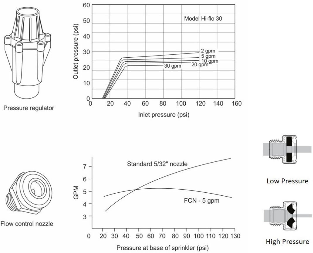
It is not always possible to satisfy the allowable pressure variation limitation for laterals. In such cases pressure regulators or pressure compensating nozzles (flow control) can be used to control sprinkler discharge. A regulator can provide nearly constant outlet pressure for a range of inlet pressures (Figure 11.10). This provides the same pressure to sprinklers along the lateral and produces high uniformity; however, a higher inlet pressure is required so that all sprinklers receive the design pressure. Regulators may not be required along the entire lateral if the same end of the lateral is always next to the mainline. Some pressure is lost as water flows through the regulator so inlet pressure must be increased to overcome this loss. The regulators also increase the operating and the initial cost of the system. Pressure compensating nozzles serve the same purpose and may reduce both the operating and installation costs compared to pressure regulators. Some designs of pressure compensating nozzles include flexible orifices that contract at high pressure and expand under low pressure. The change of the orifice size regulates the flow as shown in Figure 11.10. Compensating nozzles generally have a smaller operating range than regulators.