
1.2: Module 2 - Sketches
- Page ID
- 25068

\( \newcommand{\vecs}[1]{\overset { \scriptstyle \rightharpoonup} {\mathbf{#1}} } \)
\( \newcommand{\vecd}[1]{\overset{-\!-\!\rightharpoonup}{\vphantom{a}\smash {#1}}} \)
\( \newcommand{\dsum}{\displaystyle\sum\limits} \)
\( \newcommand{\dint}{\displaystyle\int\limits} \)
\( \newcommand{\dlim}{\displaystyle\lim\limits} \)
\( \newcommand{\id}{\mathrm{id}}\) \( \newcommand{\Span}{\mathrm{span}}\)
( \newcommand{\kernel}{\mathrm{null}\,}\) \( \newcommand{\range}{\mathrm{range}\,}\)
\( \newcommand{\RealPart}{\mathrm{Re}}\) \( \newcommand{\ImaginaryPart}{\mathrm{Im}}\)
\( \newcommand{\Argument}{\mathrm{Arg}}\) \( \newcommand{\norm}[1]{\| #1 \|}\)
\( \newcommand{\inner}[2]{\langle #1, #2 \rangle}\)
\( \newcommand{\Span}{\mathrm{span}}\)
\( \newcommand{\id}{\mathrm{id}}\)
\( \newcommand{\Span}{\mathrm{span}}\)
\( \newcommand{\kernel}{\mathrm{null}\,}\)
\( \newcommand{\range}{\mathrm{range}\,}\)
\( \newcommand{\RealPart}{\mathrm{Re}}\)
\( \newcommand{\ImaginaryPart}{\mathrm{Im}}\)
\( \newcommand{\Argument}{\mathrm{Arg}}\)
\( \newcommand{\norm}[1]{\| #1 \|}\)
\( \newcommand{\inner}[2]{\langle #1, #2 \rangle}\)
\( \newcommand{\Span}{\mathrm{span}}\) \( \newcommand{\AA}{\unicode[.8,0]{x212B}}\)
\( \newcommand{\vectorA}[1]{\vec{#1}} % arrow\)
\( \newcommand{\vectorAt}[1]{\vec{\text{#1}}} % arrow\)
\( \newcommand{\vectorB}[1]{\overset { \scriptstyle \rightharpoonup} {\mathbf{#1}} } \)
\( \newcommand{\vectorC}[1]{\textbf{#1}} \)
\( \newcommand{\vectorD}[1]{\overrightarrow{#1}} \)
\( \newcommand{\vectorDt}[1]{\overrightarrow{\text{#1}}} \)
\( \newcommand{\vectE}[1]{\overset{-\!-\!\rightharpoonup}{\vphantom{a}\smash{\mathbf {#1}}}} \)
\( \newcommand{\vecs}[1]{\overset { \scriptstyle \rightharpoonup} {\mathbf{#1}} } \)
\(\newcommand{\longvect}{\overrightarrow}\)
\( \newcommand{\vecd}[1]{\overset{-\!-\!\rightharpoonup}{\vphantom{a}\smash {#1}}} \)
\(\newcommand{\avec}{\mathbf a}\) \(\newcommand{\bvec}{\mathbf b}\) \(\newcommand{\cvec}{\mathbf c}\) \(\newcommand{\dvec}{\mathbf d}\) \(\newcommand{\dtil}{\widetilde{\mathbf d}}\) \(\newcommand{\evec}{\mathbf e}\) \(\newcommand{\fvec}{\mathbf f}\) \(\newcommand{\nvec}{\mathbf n}\) \(\newcommand{\pvec}{\mathbf p}\) \(\newcommand{\qvec}{\mathbf q}\) \(\newcommand{\svec}{\mathbf s}\) \(\newcommand{\tvec}{\mathbf t}\) \(\newcommand{\uvec}{\mathbf u}\) \(\newcommand{\vvec}{\mathbf v}\) \(\newcommand{\wvec}{\mathbf w}\) \(\newcommand{\xvec}{\mathbf x}\) \(\newcommand{\yvec}{\mathbf y}\) \(\newcommand{\zvec}{\mathbf z}\) \(\newcommand{\rvec}{\mathbf r}\) \(\newcommand{\mvec}{\mathbf m}\) \(\newcommand{\zerovec}{\mathbf 0}\) \(\newcommand{\onevec}{\mathbf 1}\) \(\newcommand{\real}{\mathbb R}\) \(\newcommand{\twovec}[2]{\left[\begin{array}{r}#1 \\ #2 \end{array}\right]}\) \(\newcommand{\ctwovec}[2]{\left[\begin{array}{c}#1 \\ #2 \end{array}\right]}\) \(\newcommand{\threevec}[3]{\left[\begin{array}{r}#1 \\ #2 \\ #3 \end{array}\right]}\) \(\newcommand{\cthreevec}[3]{\left[\begin{array}{c}#1 \\ #2 \\ #3 \end{array}\right]}\) \(\newcommand{\fourvec}[4]{\left[\begin{array}{r}#1 \\ #2 \\ #3 \\ #4 \end{array}\right]}\) \(\newcommand{\cfourvec}[4]{\left[\begin{array}{c}#1 \\ #2 \\ #3 \\ #4 \end{array}\right]}\) \(\newcommand{\fivevec}[5]{\left[\begin{array}{r}#1 \\ #2 \\ #3 \\ #4 \\ #5 \\ \end{array}\right]}\) \(\newcommand{\cfivevec}[5]{\left[\begin{array}{c}#1 \\ #2 \\ #3 \\ #4 \\ #5 \\ \end{array}\right]}\) \(\newcommand{\mattwo}[4]{\left[\begin{array}{rr}#1 \amp #2 \\ #3 \amp #4 \\ \end{array}\right]}\) \(\newcommand{\laspan}[1]{\text{Span}\{#1\}}\) \(\newcommand{\bcal}{\cal B}\) \(\newcommand{\ccal}{\cal C}\) \(\newcommand{\scal}{\cal S}\) \(\newcommand{\wcal}{\cal W}\) \(\newcommand{\ecal}{\cal E}\) \(\newcommand{\coords}[2]{\left\{#1\right\}_{#2}}\) \(\newcommand{\gray}[1]{\color{gray}{#1}}\) \(\newcommand{\lgray}[1]{\color{lightgray}{#1}}\) \(\newcommand{\rank}{\operatorname{rank}}\) \(\newcommand{\row}{\text{Row}}\) \(\newcommand{\col}{\text{Col}}\) \(\renewcommand{\row}{\text{Row}}\) \(\newcommand{\nul}{\text{Nul}}\) \(\newcommand{\var}{\text{Var}}\) \(\newcommand{\corr}{\text{corr}}\) \(\newcommand{\len}[1]{\left|#1\right|}\) \(\newcommand{\bbar}{\overline{\bvec}}\) \(\newcommand{\bhat}{\widehat{\bvec}}\) \(\newcommand{\bperp}{\bvec^\perp}\) \(\newcommand{\xhat}{\widehat{\xvec}}\) \(\newcommand{\vhat}{\widehat{\vvec}}\) \(\newcommand{\uhat}{\widehat{\uvec}}\) \(\newcommand{\what}{\widehat{\wvec}}\) \(\newcommand{\Sighat}{\widehat{\Sigma}}\) \(\newcommand{\lt}{<}\) \(\newcommand{\gt}{>}\) \(\newcommand{\amp}{&}\) \(\definecolor{fillinmathshade}{gray}{0.9}\)Introduction to Sketches
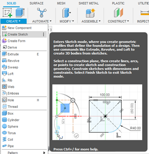
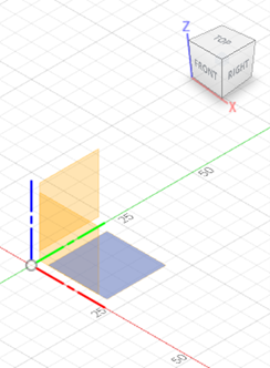
A two-dimensional (2D) sketch is the basis of any solid model created in a Computer Aided Design (CAD) package. In a new CAD file, click on the create menu and select sketch as Shown in Figure \(\PageIndex{1}\) (left). After clicking on it, the interface for the sketch opens, as shown in Figure \(\PageIndex{1}\) (right). To proceed, a plane must be selected. This plane will become the sketching plane. Note that all three planes are orthogonal to each other.
Module 2 video, Part 1:
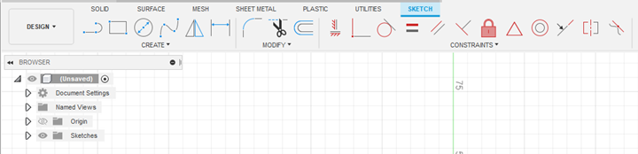
Sketch Toolbar
Once the sketching plane has been selected, there are multiple methods to sketch on the plane in order to generate the required shape. These tools are shown in Figure \(\PageIndex{2}\) and explained in the following sections.
Create and Modify Tools
The primary function of the Create and Modify tools is to allow the users to create 2D primitives and edit them.
Line and Arc
The Line and Arc tool lets the user create a line by default. To create an arc at the end of a line, click the endpoint and drag it to create the arc. (See Figure \(\PageIndex{3}\).)

2-Point Rectangle
This 2-Point Rectangle (Figure \(\PageIndex{4}\)) tool lets the user create a rectangle or a square using two points for the diagonal corners.

Center Diameter Circle
The Center Diameter Circle tool (Figure \(\PageIndex{5}\)) lets the user create a circle by defining the center point and the diameter.

Fit Point Spline
The Fit Point Spline tool (Figure \(\PageIndex{6}\)) lets the user create a spline through the selected points. A spline is a continuous smooth arc with each consecutive arc being at a tangent to the previous one.

Fillet
The Fillet tool (Figure \(\PageIndex{7}\)) places an arc of a specified radius at the intersection of two lines or arcs.

Chamfer
The Chamfer tool (Figure \(\PageIndex{8}\)) places an angled edge at the intersection of two lines. It can be defined by a combination of distance and angles.

Trim
The Trim tool (Figure \(\PageIndex{9}\)) trims a sketch curve to the nearest intersecting curve or boundary.
Offset
The Offset tool (Figure \(\PageIndex{10}\)) copies the selected curves a specified distance from the original curves.
Constraints
Once the sketch is partially or fully complete, the elements of the sketch must be constraints so the designer intent can be preserved. Once the sketch is constrained its color scheme turns from blue to black.
Horizontal and Vertical Constraints
The Horizontal and Vertical Constraints tool (Figure \(\PageIndex{11}\)) constrains a single line, or two points, to lie on either the vertical or the horizontal axis, whichever is closer to the current alignment.
Coincident Constraints
The Coincident Constraints tool (Figure \(\PageIndex{12}\)) constrains the position of two points together. It can also work for constraining the position of a point and a line or a curve together.
Tangent Constraints
The Tangent Constraints tool (Figure \(\PageIndex{13}\)) constrains a curve and another object so that they touch at a single point but never cross each other.
Equal Constraints
The Equal Constraints tool (Figure \(\PageIndex{14}\)) constrains similar objects so that their sizes are identical. A change in size in one object will automatically adjust the size of the other component to reflect this change.
Parallel Constraints
The Parallel Constraints tool (Figure \(\PageIndex{15}\)) constrains two lines so that they extend in the same direction and do not intersect.
Perpendicular Constraints
The Perpendicular Constraints tool (Figure \(\PageIndex{16}\)) constrains two objects so that they lie perpendicular to each other.
Fix and Unfix Constraints
The Fix and Unfix Constraints tool (Figure \(\PageIndex{17}\)) constrains the size and location of the point or object. A word of caution, this constrain should be used only if none of the other constrains are pertinent.
Concentric
The Concentric tool (Figure \(\PageIndex{18}\)) constrains two or more arcs, circles, or ellipses to the same center point.
Colinear
The Colinear tool (Figure \(\PageIndex{19}\)) constrains two or more objects so that they share a common line.
Symmetry
The Symmetry tool (Figure \(\PageIndex{20}\)) constrains two or more objects so that they are symmetrical.
Objective: Create the following sketch
Module 2 Video, parts 2 & 3
Steps to create the final sketch:
Step 1 - Create new design
Create a new design and sketch on the front plane.
Step 2 - Sketch concentric circles
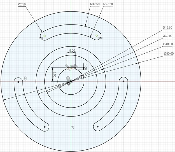
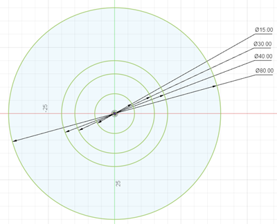
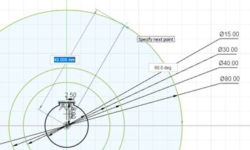
Create our concentric circles with diameter 15 millimeters (mm), 30 mm, 40 mm, and 80 mm. Use the origin as the center point for the circles. Right click on each circle and select sketch dimensions and ensure the dimensions are accurate. Notice that no constraints have been applied to any of the circles and hence their color is green. (See Figure \(\PageIndex{22}\).)
Step 3 - Create lines
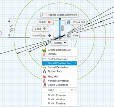
Next, create a line measuring 8 mm from the center of the circle stretching up along the vertical axis. Next, right click on the line and select construction line. This is done because this line is an aid to creating the sketch and not part of the sketch itself. (See Figure \(\PageIndex{23}\).)
Step 4 - Draw lines
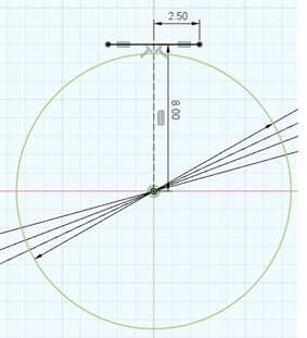
At the end point of the line constructed in the previous step, draw a vertical line of length 2.5 mm. Repeat this on the other side. Use the equal to constraint to make sure each line is 2.5 mm and the total length is 5.00 mm. (See Figure \(\PageIndex{24}\).)
Step 5 - Drop and trim line segments
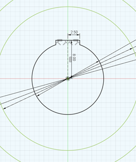
Drop line segments to the circle from the end points of the 5 mm line created in the previous step. Then trim the segment of the circle in between the lines. Also notice that this part of the sketch is now fully constrained, while the rest of the circles are still not constrained. (Figure \(\PageIndex{25}\).)
Step 6 - Draw lines
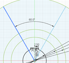
Draw two lines at an angle of 60° and 120° from the horizontal as shown in Figure \(\PageIndex{26}\) below. The angle between the two lines is also 60°.
Step 7 - Draw concentric circle segments
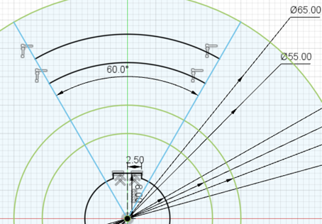
Draw two concentric circles with diameters 55 mm and 65 mm. Trim the segments of the concentric circles to look like the following figure. (See Figure \(\PageIndex{27}\).)
Step 8 - Create the three-point arcs
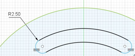
Create a three-point arc on each side of the concentric segments as shown in Figure \(\PageIndex{28}\) below. The radius for each arc is 2.5 mm. You can use equal constraint to ensure the arcs have the same diameter.
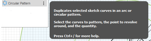
Step 9 - Use circular pattern tool
In order to create three such features, use the circular pattern tool that can be found under the create drop down menu. (See Figure \(\PageIndex{29}\).)
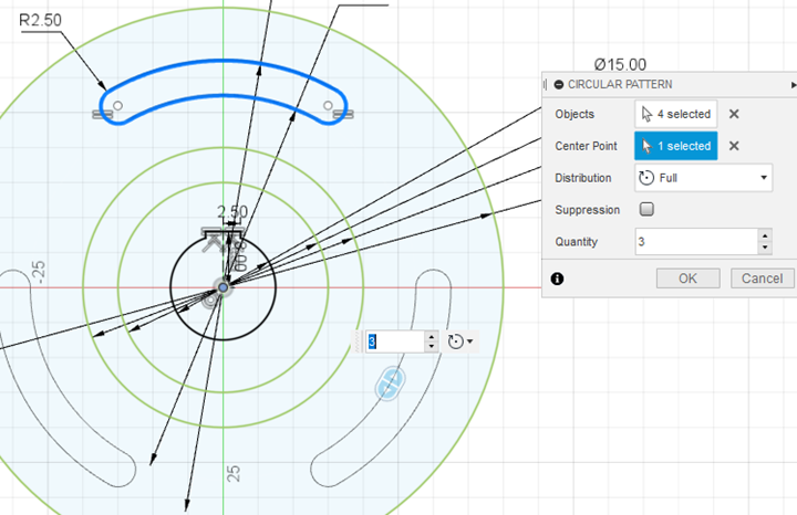
Step 10 - Enter parameters
In order to create the pattern, the parameters in the dialogue box are shown in Figure \(\PageIndex{30}\) below. Select all the four (4) arcs that form the slot. The center point is the center of the circle and the total quantity of pattern objects to be created is three (3).
Step 11 - Constrain sketch
Use the lock constraint tool to ensure the entire sketch is constrained and the color of all sketch elements should turn black. (See Figure \(\PageIndex{31}\).) Remember to save your work.