1.9: Final Project - Assembly
- Page ID
- 25082

\( \newcommand{\vecs}[1]{\overset { \scriptstyle \rightharpoonup} {\mathbf{#1}} } \)
\( \newcommand{\vecd}[1]{\overset{-\!-\!\rightharpoonup}{\vphantom{a}\smash {#1}}} \)
\( \newcommand{\id}{\mathrm{id}}\) \( \newcommand{\Span}{\mathrm{span}}\)
( \newcommand{\kernel}{\mathrm{null}\,}\) \( \newcommand{\range}{\mathrm{range}\,}\)
\( \newcommand{\RealPart}{\mathrm{Re}}\) \( \newcommand{\ImaginaryPart}{\mathrm{Im}}\)
\( \newcommand{\Argument}{\mathrm{Arg}}\) \( \newcommand{\norm}[1]{\| #1 \|}\)
\( \newcommand{\inner}[2]{\langle #1, #2 \rangle}\)
\( \newcommand{\Span}{\mathrm{span}}\)
\( \newcommand{\id}{\mathrm{id}}\)
\( \newcommand{\Span}{\mathrm{span}}\)
\( \newcommand{\kernel}{\mathrm{null}\,}\)
\( \newcommand{\range}{\mathrm{range}\,}\)
\( \newcommand{\RealPart}{\mathrm{Re}}\)
\( \newcommand{\ImaginaryPart}{\mathrm{Im}}\)
\( \newcommand{\Argument}{\mathrm{Arg}}\)
\( \newcommand{\norm}[1]{\| #1 \|}\)
\( \newcommand{\inner}[2]{\langle #1, #2 \rangle}\)
\( \newcommand{\Span}{\mathrm{span}}\) \( \newcommand{\AA}{\unicode[.8,0]{x212B}}\)
\( \newcommand{\vectorA}[1]{\vec{#1}} % arrow\)
\( \newcommand{\vectorAt}[1]{\vec{\text{#1}}} % arrow\)
\( \newcommand{\vectorB}[1]{\overset { \scriptstyle \rightharpoonup} {\mathbf{#1}} } \)
\( \newcommand{\vectorC}[1]{\textbf{#1}} \)
\( \newcommand{\vectorD}[1]{\overrightarrow{#1}} \)
\( \newcommand{\vectorDt}[1]{\overrightarrow{\text{#1}}} \)
\( \newcommand{\vectE}[1]{\overset{-\!-\!\rightharpoonup}{\vphantom{a}\smash{\mathbf {#1}}}} \)
\( \newcommand{\vecs}[1]{\overset { \scriptstyle \rightharpoonup} {\mathbf{#1}} } \)
\( \newcommand{\vecd}[1]{\overset{-\!-\!\rightharpoonup}{\vphantom{a}\smash {#1}}} \)
\(\newcommand{\avec}{\mathbf a}\) \(\newcommand{\bvec}{\mathbf b}\) \(\newcommand{\cvec}{\mathbf c}\) \(\newcommand{\dvec}{\mathbf d}\) \(\newcommand{\dtil}{\widetilde{\mathbf d}}\) \(\newcommand{\evec}{\mathbf e}\) \(\newcommand{\fvec}{\mathbf f}\) \(\newcommand{\nvec}{\mathbf n}\) \(\newcommand{\pvec}{\mathbf p}\) \(\newcommand{\qvec}{\mathbf q}\) \(\newcommand{\svec}{\mathbf s}\) \(\newcommand{\tvec}{\mathbf t}\) \(\newcommand{\uvec}{\mathbf u}\) \(\newcommand{\vvec}{\mathbf v}\) \(\newcommand{\wvec}{\mathbf w}\) \(\newcommand{\xvec}{\mathbf x}\) \(\newcommand{\yvec}{\mathbf y}\) \(\newcommand{\zvec}{\mathbf z}\) \(\newcommand{\rvec}{\mathbf r}\) \(\newcommand{\mvec}{\mathbf m}\) \(\newcommand{\zerovec}{\mathbf 0}\) \(\newcommand{\onevec}{\mathbf 1}\) \(\newcommand{\real}{\mathbb R}\) \(\newcommand{\twovec}[2]{\left[\begin{array}{r}#1 \\ #2 \end{array}\right]}\) \(\newcommand{\ctwovec}[2]{\left[\begin{array}{c}#1 \\ #2 \end{array}\right]}\) \(\newcommand{\threevec}[3]{\left[\begin{array}{r}#1 \\ #2 \\ #3 \end{array}\right]}\) \(\newcommand{\cthreevec}[3]{\left[\begin{array}{c}#1 \\ #2 \\ #3 \end{array}\right]}\) \(\newcommand{\fourvec}[4]{\left[\begin{array}{r}#1 \\ #2 \\ #3 \\ #4 \end{array}\right]}\) \(\newcommand{\cfourvec}[4]{\left[\begin{array}{c}#1 \\ #2 \\ #3 \\ #4 \end{array}\right]}\) \(\newcommand{\fivevec}[5]{\left[\begin{array}{r}#1 \\ #2 \\ #3 \\ #4 \\ #5 \\ \end{array}\right]}\) \(\newcommand{\cfivevec}[5]{\left[\begin{array}{c}#1 \\ #2 \\ #3 \\ #4 \\ #5 \\ \end{array}\right]}\) \(\newcommand{\mattwo}[4]{\left[\begin{array}{rr}#1 \amp #2 \\ #3 \amp #4 \\ \end{array}\right]}\) \(\newcommand{\laspan}[1]{\text{Span}\{#1\}}\) \(\newcommand{\bcal}{\cal B}\) \(\newcommand{\ccal}{\cal C}\) \(\newcommand{\scal}{\cal S}\) \(\newcommand{\wcal}{\cal W}\) \(\newcommand{\ecal}{\cal E}\) \(\newcommand{\coords}[2]{\left\{#1\right\}_{#2}}\) \(\newcommand{\gray}[1]{\color{gray}{#1}}\) \(\newcommand{\lgray}[1]{\color{lightgray}{#1}}\) \(\newcommand{\rank}{\operatorname{rank}}\) \(\newcommand{\row}{\text{Row}}\) \(\newcommand{\col}{\text{Col}}\) \(\renewcommand{\row}{\text{Row}}\) \(\newcommand{\nul}{\text{Nul}}\) \(\newcommand{\var}{\text{Var}}\) \(\newcommand{\corr}{\text{corr}}\) \(\newcommand{\len}[1]{\left|#1\right|}\) \(\newcommand{\bbar}{\overline{\bvec}}\) \(\newcommand{\bhat}{\widehat{\bvec}}\) \(\newcommand{\bperp}{\bvec^\perp}\) \(\newcommand{\xhat}{\widehat{\xvec}}\) \(\newcommand{\vhat}{\widehat{\vvec}}\) \(\newcommand{\uhat}{\widehat{\uvec}}\) \(\newcommand{\what}{\widehat{\wvec}}\) \(\newcommand{\Sighat}{\widehat{\Sigma}}\) \(\newcommand{\lt}{<}\) \(\newcommand{\gt}{>}\) \(\newcommand{\amp}{&}\) \(\definecolor{fillinmathshade}{gray}{0.9}\)Introduction
A C–clamp is a cheap and portable alternative to a table vise. It is made of a piece of metal shaped like a 'C' and a bolt with a flat head. The bolt can go back and forth to clamp or unclamp a workpiece. The assembly of these two components forms a C-clamp.
Create the body of the C-clamp
In this section, the body of the C-clamp will be sketched and then then extruded.
Step 1 - Initial sketch of the clamp
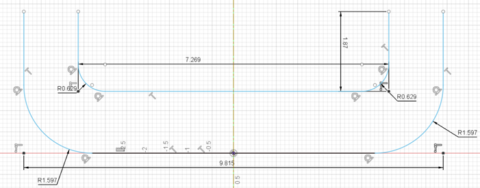
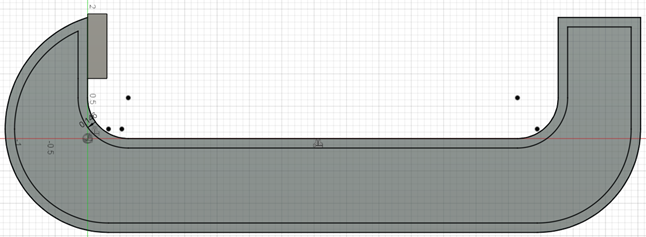
Sketch the initial body as shown in Figure \(\PageIndex{1}\). Make sure the units are inches. Create the U shape using the Line option. The length of the line is 9.815 inches. Then round off the edges using the Fillet option. The radius of the fillet on each side is 1.597 inches. The inner line is offset at a distance of 1.45 inches. The fillet radius on this inner line is 0.629 inches.
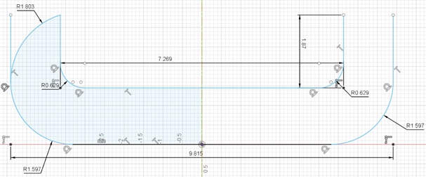
Then, sketch a three-point arc on the left side of the initial sketch as shown in Figure \(\PageIndex{2}\). The radius of this arc is 1.803 inches.
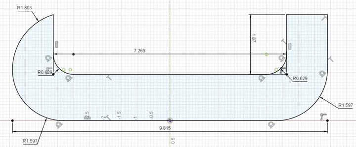
Next, use the Trim option to remove the extra bit of vertical line left over, as shown in Figure \(\PageIndex{3}\).
Finally, draw a horizontal line on the right side of the initial sketch to complete the sketch. The completed sketch is shown Figure \(\PageIndex{3}\).
Step 2 - Extrude the clamp
Extrude the sketch completed in the previous step. The extrude parameters are shown in the dialog box. The completed extrude and the parameters are shown in Figure \(\PageIndex{4}\).
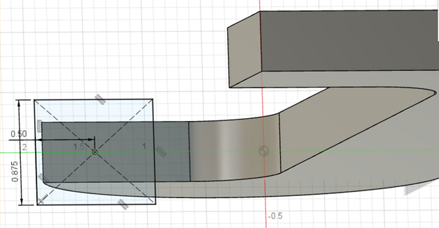
Step 3 - Sketch clamping surface
Select the inner surface of the clamp and sketch a square of side 0.875 inches, with its center at 1.5 inches away from the edge of the clamp as shown in Figure \(\PageIndex{5}\).
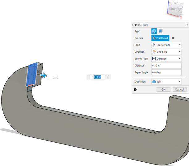
Step 4 - Extrude the clamping surface
Extrude the sketch created in the previous step to a distance of 0.30 inches as shown in Figure \(\PageIndex{6}\).
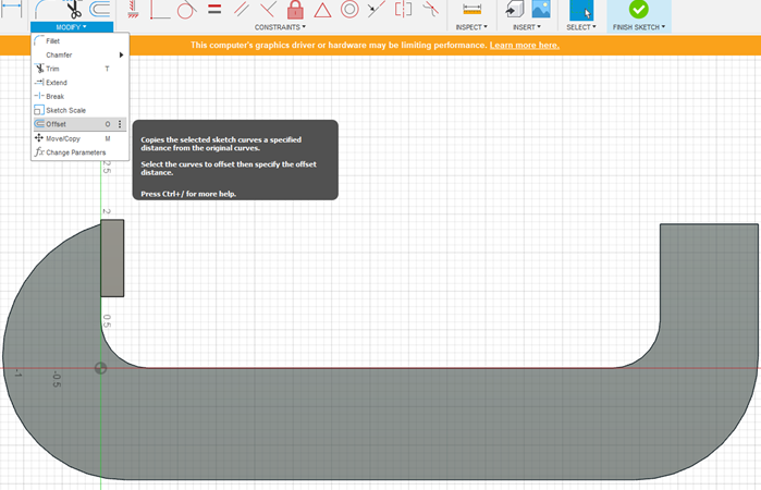
Step 5 - Create a lip on the edge of the clamp
Use the offset option and copy the existing edge of the clamp as shown in Figure \(\PageIndex{7}\). This offset sketch will be on the inside of the existing curve and at a distance of 0.146 inches as shown in Figure \(\PageIndex{8}\).
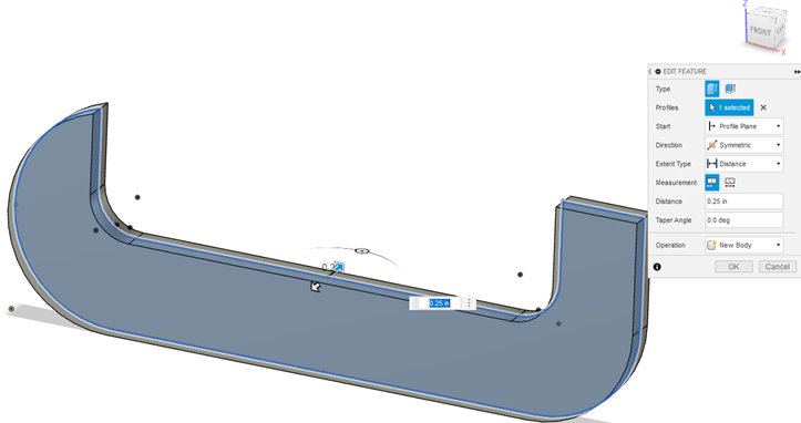
Step 6 - Extrude the lip
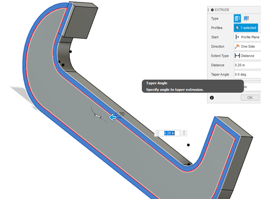
Extrude the offset sketch created in the previous step to a distance of 0.20 inches. The extrude parameters are shown in Figure \(\PageIndex{9}\).
Step 7 - Apply Fillet to the extruded lip
Apply a Fillet of 0.05 inches to the lip created in step 2.6. The end result of the applied fillets is shown in Figure \(\PageIndex{10}\).

Step 8 - Apply Fillet to the edges of the clamping surface
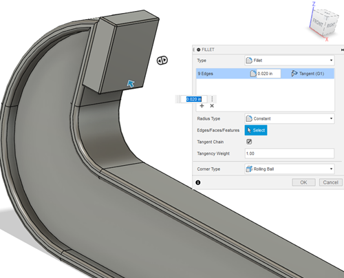
Apply a Fillet of radius 0.020 inches to the edges of the clamping surface that was created in step 4. The result of this applied Fillet is shown in Figure \(\PageIndex{11}\).
Step 9 - Sketch text on the clamp surface
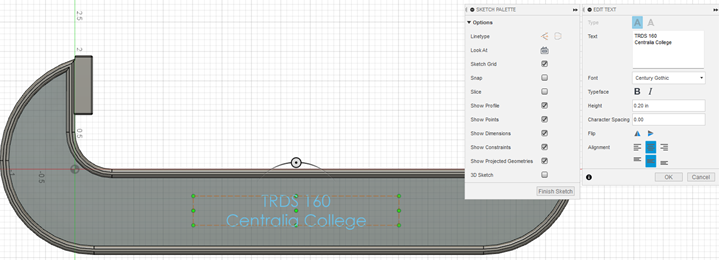
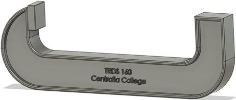
Select the surface of the clamp and sketch text on the surface as shown in Figure \(\PageIndex{12}\). In the Edit Text dialog box, enter the “TRDS 160” in the first line and “Centralia College” in the second line.
Step 10 - Extrude text on the clamp surface
Select the sketch text created in the previous step. Extrude the text to a height of 0.20 inches. The extruded text is shown in Figure \(\PageIndex{13}\).
Step 11 - Repeat steps 5, 6, and 7 on the other side of the clamp.
Step 12 - Sketch a circle on the far side of the clamp.
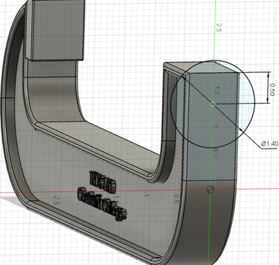
Sketch a circle of diameter 1.40 inches and with its center at 0.50 inches below the edge as shown in Figure \(\PageIndex{14}\).
Step 13 - Extrude the circle
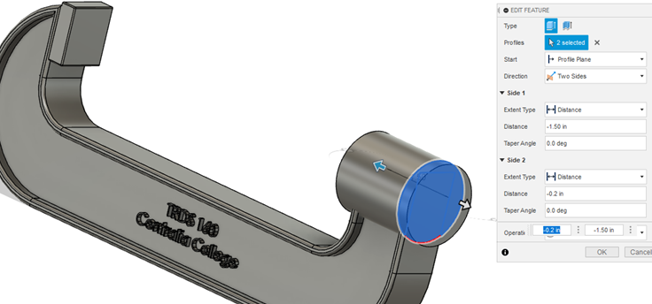
Extrude the circle created in the previous step to a distance of 1.50 inches as shown in Figure \(\PageIndex{15}\).
Step 14 - Sketch a circle on the feature created in step 13
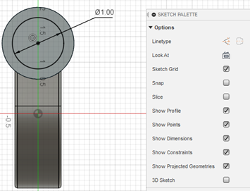
Sketch a concentric circle of diameter of 1.00 inches as shown in Figure \(\PageIndex{16}\).
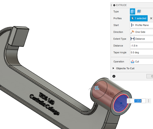
Step 15 - Extrude a hole from the feature created in step 2.14
Use the Extrude Cut option as shown in Figure \(\PageIndex{17}\) to cut a through hole using the circle created in the previous step.
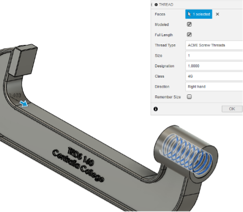
Step 16 - Create threads on the inside of the hole created in step 15
Add right-handed ACME screw threads of size 1, designation 1, and class 4G, as shown in Figure \(\PageIndex{18}\).
Step 17 - Save this file.
Create the Clamp Spindle
In this section, the clamp spindle will be sketched and then then extruded.
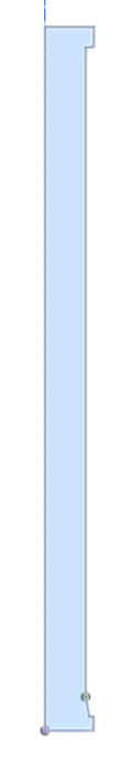
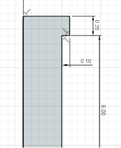
Step 1 - Create the sketch of the clamp spindle
Create a new file. Make sure the units are inches. Add a centerline and sketch the profile as shown in the Figure \(\PageIndex{19}\).
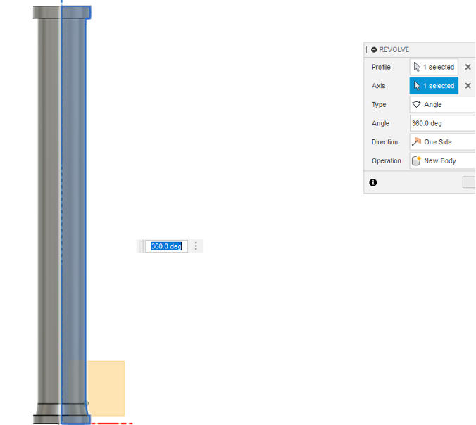
Step 2 - Revolve the profile created in Spindle step 1
Use the Revolve option to create a cylindrical profile as shown in Figure \(\PageIndex{20}\).To make sure the profile is complete choose an angle of 360°.
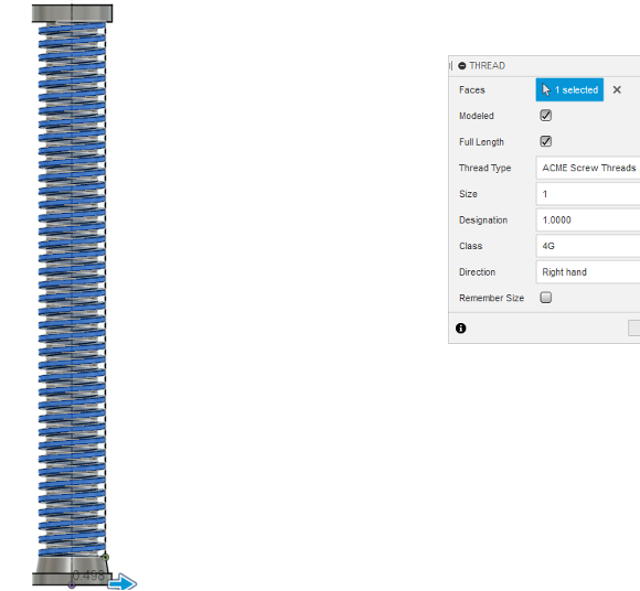
Step 3 - Add threads to the clamp spindle
Add right-handed, ACME threads to the clamp spindle threads of size 1, designation 1, and class 4G, to the clamp spindle as shown in Figure \(\PageIndex{21}\).
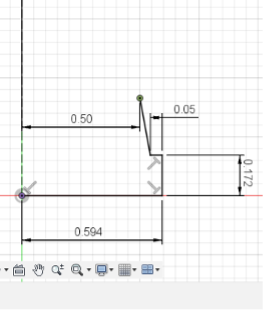
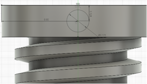
Step 4 - Sketch a circle on the clamp spindle
Create a sketch of a circle of diameter 0.175 inches that is 0.124 inches away from the top edge of the clamp spindle and 0.60 inches from the side of the clamp spindle as shown in Figure \(\PageIndex{22}\).
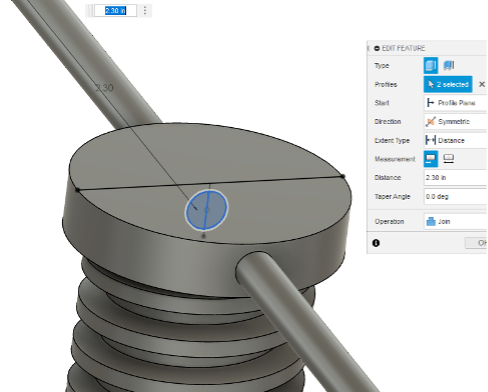
Step 5 - Extrude circle to create the swivel bar
Extrude the circle created in the previous step symmetrically to a length of 2.30 inches as shown in Figure \(\PageIndex{23}\).
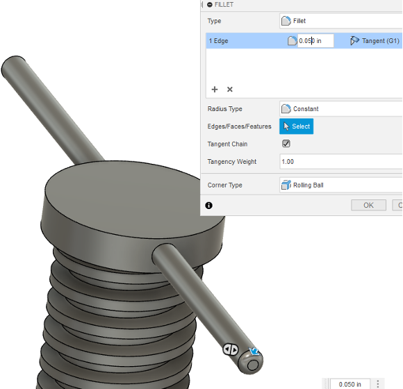
Step 6 - Create fillet at the edge of the swivel bar
Create a fillet of radius 0.050 inches as shown in Figure \(\PageIndex{24}\).
Step 7 - Save this file.
Assemble the body clamp and clamp spindle
In this section the body of the clamp and clamp spindle will be assembled as shown in Figure \(\PageIndex{25}\).
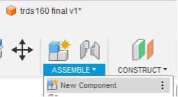
Step 1 - Insert components in the new file
Create a new file and add the clamp and the spindle by using the Assemble option as shown in Figure \(\PageIndex{26}\).
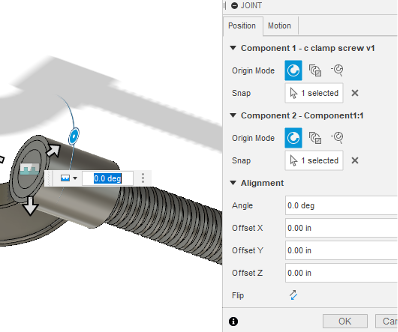
Step 2 - Create Joint
Use the Joint command and select the origin on the top side of the spindle and the origin located on the end of the spindle hole as shown in Figure \(\PageIndex{27}\).
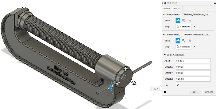
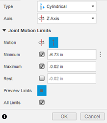
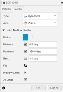
Step 3 - Edit Joint
Right click the joint to edit the parameters. Select a cylindrical joint and edit the rotational and linear joint limits as shown in Figure \(\PageIndex{28}\).
Step 4 - Verify the joint parameters
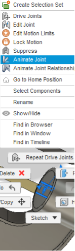
Right click on the joint and select the Animate Joint option as shown in Figure \(\PageIndex{29}\). This will animate the joint and verify if the parameters worked out as required.