
1.2: Module 2 Inventor’s User Interface
- Page ID
- 19866

\( \newcommand{\vecs}[1]{\overset { \scriptstyle \rightharpoonup} {\mathbf{#1}} } \)
\( \newcommand{\vecd}[1]{\overset{-\!-\!\rightharpoonup}{\vphantom{a}\smash {#1}}} \)
\( \newcommand{\id}{\mathrm{id}}\) \( \newcommand{\Span}{\mathrm{span}}\)
( \newcommand{\kernel}{\mathrm{null}\,}\) \( \newcommand{\range}{\mathrm{range}\,}\)
\( \newcommand{\RealPart}{\mathrm{Re}}\) \( \newcommand{\ImaginaryPart}{\mathrm{Im}}\)
\( \newcommand{\Argument}{\mathrm{Arg}}\) \( \newcommand{\norm}[1]{\| #1 \|}\)
\( \newcommand{\inner}[2]{\langle #1, #2 \rangle}\)
\( \newcommand{\Span}{\mathrm{span}}\)
\( \newcommand{\id}{\mathrm{id}}\)
\( \newcommand{\Span}{\mathrm{span}}\)
\( \newcommand{\kernel}{\mathrm{null}\,}\)
\( \newcommand{\range}{\mathrm{range}\,}\)
\( \newcommand{\RealPart}{\mathrm{Re}}\)
\( \newcommand{\ImaginaryPart}{\mathrm{Im}}\)
\( \newcommand{\Argument}{\mathrm{Arg}}\)
\( \newcommand{\norm}[1]{\| #1 \|}\)
\( \newcommand{\inner}[2]{\langle #1, #2 \rangle}\)
\( \newcommand{\Span}{\mathrm{span}}\) \( \newcommand{\AA}{\unicode[.8,0]{x212B}}\)
\( \newcommand{\vectorA}[1]{\vec{#1}} % arrow\)
\( \newcommand{\vectorAt}[1]{\vec{\text{#1}}} % arrow\)
\( \newcommand{\vectorB}[1]{\overset { \scriptstyle \rightharpoonup} {\mathbf{#1}} } \)
\( \newcommand{\vectorC}[1]{\textbf{#1}} \)
\( \newcommand{\vectorD}[1]{\overrightarrow{#1}} \)
\( \newcommand{\vectorDt}[1]{\overrightarrow{\text{#1}}} \)
\( \newcommand{\vectE}[1]{\overset{-\!-\!\rightharpoonup}{\vphantom{a}\smash{\mathbf {#1}}}} \)
\( \newcommand{\vecs}[1]{\overset { \scriptstyle \rightharpoonup} {\mathbf{#1}} } \)
\( \newcommand{\vecd}[1]{\overset{-\!-\!\rightharpoonup}{\vphantom{a}\smash {#1}}} \)
\(\newcommand{\avec}{\mathbf a}\) \(\newcommand{\bvec}{\mathbf b}\) \(\newcommand{\cvec}{\mathbf c}\) \(\newcommand{\dvec}{\mathbf d}\) \(\newcommand{\dtil}{\widetilde{\mathbf d}}\) \(\newcommand{\evec}{\mathbf e}\) \(\newcommand{\fvec}{\mathbf f}\) \(\newcommand{\nvec}{\mathbf n}\) \(\newcommand{\pvec}{\mathbf p}\) \(\newcommand{\qvec}{\mathbf q}\) \(\newcommand{\svec}{\mathbf s}\) \(\newcommand{\tvec}{\mathbf t}\) \(\newcommand{\uvec}{\mathbf u}\) \(\newcommand{\vvec}{\mathbf v}\) \(\newcommand{\wvec}{\mathbf w}\) \(\newcommand{\xvec}{\mathbf x}\) \(\newcommand{\yvec}{\mathbf y}\) \(\newcommand{\zvec}{\mathbf z}\) \(\newcommand{\rvec}{\mathbf r}\) \(\newcommand{\mvec}{\mathbf m}\) \(\newcommand{\zerovec}{\mathbf 0}\) \(\newcommand{\onevec}{\mathbf 1}\) \(\newcommand{\real}{\mathbb R}\) \(\newcommand{\twovec}[2]{\left[\begin{array}{r}#1 \\ #2 \end{array}\right]}\) \(\newcommand{\ctwovec}[2]{\left[\begin{array}{c}#1 \\ #2 \end{array}\right]}\) \(\newcommand{\threevec}[3]{\left[\begin{array}{r}#1 \\ #2 \\ #3 \end{array}\right]}\) \(\newcommand{\cthreevec}[3]{\left[\begin{array}{c}#1 \\ #2 \\ #3 \end{array}\right]}\) \(\newcommand{\fourvec}[4]{\left[\begin{array}{r}#1 \\ #2 \\ #3 \\ #4 \end{array}\right]}\) \(\newcommand{\cfourvec}[4]{\left[\begin{array}{c}#1 \\ #2 \\ #3 \\ #4 \end{array}\right]}\) \(\newcommand{\fivevec}[5]{\left[\begin{array}{r}#1 \\ #2 \\ #3 \\ #4 \\ #5 \\ \end{array}\right]}\) \(\newcommand{\cfivevec}[5]{\left[\begin{array}{c}#1 \\ #2 \\ #3 \\ #4 \\ #5 \\ \end{array}\right]}\) \(\newcommand{\mattwo}[4]{\left[\begin{array}{rr}#1 \amp #2 \\ #3 \amp #4 \\ \end{array}\right]}\) \(\newcommand{\laspan}[1]{\text{Span}\{#1\}}\) \(\newcommand{\bcal}{\cal B}\) \(\newcommand{\ccal}{\cal C}\) \(\newcommand{\scal}{\cal S}\) \(\newcommand{\wcal}{\cal W}\) \(\newcommand{\ecal}{\cal E}\) \(\newcommand{\coords}[2]{\left\{#1\right\}_{#2}}\) \(\newcommand{\gray}[1]{\color{gray}{#1}}\) \(\newcommand{\lgray}[1]{\color{lightgray}{#1}}\) \(\newcommand{\rank}{\operatorname{rank}}\) \(\newcommand{\row}{\text{Row}}\) \(\newcommand{\col}{\text{Col}}\) \(\renewcommand{\row}{\text{Row}}\) \(\newcommand{\nul}{\text{Nul}}\) \(\newcommand{\var}{\text{Var}}\) \(\newcommand{\corr}{\text{corr}}\) \(\newcommand{\len}[1]{\left|#1\right|}\) \(\newcommand{\bbar}{\overline{\bvec}}\) \(\newcommand{\bhat}{\widehat{\bvec}}\) \(\newcommand{\bperp}{\bvec^\perp}\) \(\newcommand{\xhat}{\widehat{\xvec}}\) \(\newcommand{\vhat}{\widehat{\vvec}}\) \(\newcommand{\uhat}{\widehat{\uvec}}\) \(\newcommand{\what}{\widehat{\wvec}}\) \(\newcommand{\Sighat}{\widehat{\Sigma}}\) \(\newcommand{\lt}{<}\) \(\newcommand{\gt}{>}\) \(\newcommand{\amp}{&}\) \(\definecolor{fillinmathshade}{gray}{0.9}\)2
Module 2 Inventor’s User Interface
Wally Baumback
Learning Outcomes
When you have completed this module, you will be able to:
- Describe template files, part files, sketches, and 3D solid models.
- Describe and configure Inventor’s user interface, its menus, and use of the mouse.
- Apply the NEW, SAVE, and CLOSE commands to create a new part file using a template plus name, save, and close a file.
Inventor’s Graphic Window
When a file is active, Inventor will display the Graphic window. The Graphic window has two different modes, the Sketch mode and the Model mode. The Sketch mode is used to create and edit 2D sketches that are then extruded or revolved to create 3D solid models. The Model mode is used to view, manipulate and modify 3D solid models. You can switch between these two modes to construct or edit and create the solid model. The mode that is currently displayed is called the current mode. The Model mode must be the current mode to save the file.
A 3D Solid Model
A 3D solid model, Figure 2-1, is the best possible computerized representation of a real object. A solid model can be colored or rendered plus the mass properties can be obtained from it. Mass properties are attributes such as volume, weight, surface area, moments of inertia, and centre of gravity. They are taught in Module 20.
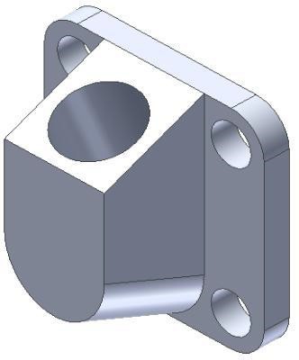
A 3D Solid Model
An Inventor File
Regardless of the type of files that are created using Inventor, they are called files as compared to files created on a CAD system which are typically called drawings. A file can be a 3D solid model (called a part), an assembly, a presentation, or a drawing created in Inventor and saved in digital format. The four types of files, taught in this book, that Inventor can create and save are part files, assembly files, presentation files, and drawing files.
A Part File
A part file is one 3D solid model. A part file has the file extension .ipt which is an acronym for Inventor ParT. A part file can be used on its own, used to create a working drawing, used as part of an assembly file, or used as part of a presentation file. Assembly and presentation files are taught in Module 21 to Module 26.
Starting a New File
A new file is started using the NEW command. The NEW command forces you to select the template file that will be used to create the new file. Every new Inventor file must be created from an existing template file. The file currently being editing in Inventor is called the current file or sometimes the active file.
Templates
A template file is simply an Inventor file, set with the desired parameters by its creator, named, and saved. As part of the Inventor book there are two distinct sets of templates provided. One set is in english units and the other set is in metric units. The English templates use the base unit of inches and the metric templates use the base unit of millimeters. Template files can also contain modelling objects so that several similar parts can easily be started from a common pre-built unit.
Saving Files
Inventor keeps the current file in RAM memory. If the computer cashes or the power fails while the operator is working on a file, all the work on the file, since the last time it was saved, will be lost. When the file is saved it saves the current file that is in RAM memory onto the disk drive.
Ensure that the current file is saved frequently to avoid losing production time. You should get into the habit of saving the current file every 5 to 10 minutes.
Inventor Command: NEW
The NEW command is used to start a new file.
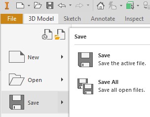
Inventor Command: SAVE
The SAVE command is used to save the current file from RAM memory onto the disk drive.
Shortcut: CTRL-S
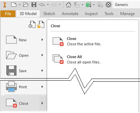
Inventor Command: CLOSE
The CLOSE command is used to close the current file.
Shortcut: None
Inventor’s Menus
Inventor has many different menus that are used by you to give instructions to Inventor while constructing and editing files. The Inventor menus taught in the Inventor book are the Pull-down menu, the Ribbon menu, the Quick Access toolbar, the Browser bar, and the Right-click menu.
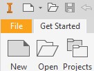
Inventor’s Pull-Down Menu
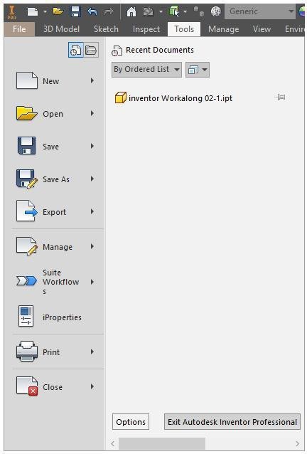
To pull down Inventor’s Pull-down menu, click the File tab. If the pull down menu item has a small solid triangle at the end, it has a flyout menu associated with it. If you move the cursor on the triangle, the flyout menu will display. See Figure 2-2.
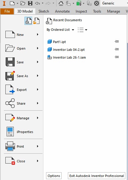
The Pull-Down Menu
Ribbon Menu
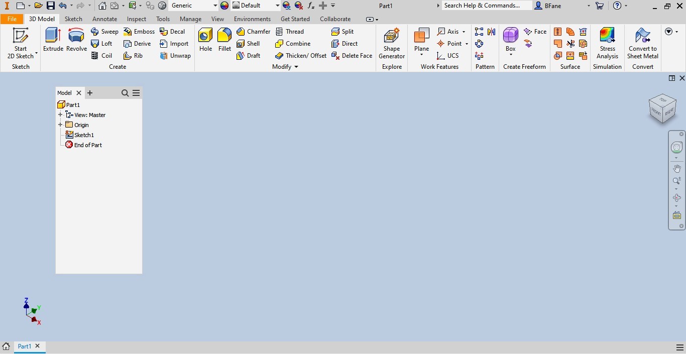
The Ribbon menu is used for most of your work in Inventor. See Figure 2-3.
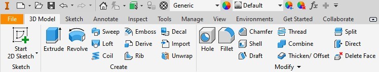
A Typical Ribbon Menu
Browser Bar
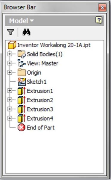
The Browser bar displays the hierarchical structure of the model or assembly of the current file. It is your most important and most-used tool to create and modify objects within files. The Browser bar will be taught in more detail in future modules. It is normally docked on the left side of the Graphic window. See Figure 2-4.
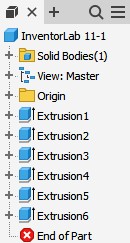
Browser Bar
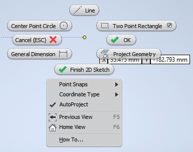
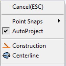
Right-Click Menu
When the right mouse button is clicked, it displays the Right-click menu. See Figure 2-5. It is sometimes called the Cursor menu since it displays at the current location of the cursor. This menu changes automatically depending on the current command or operation being performed. It usually takes the new user a bit of time to get used to using this menu.
Status Bar
The Status bar is permanently located along the bottom of the Graphic window. It displays the prompts that the current command is issuing, as shown in Figure 2-6, as well as the coordinate locations, as shown in Figure 2-7. These prompts help you understand what information Inventor requires and the cursor location, length, and angle in the current command.

Prompt.

Information
The Graphic Cursor
The Graphic cursor is used to select menu items or objects on the sketch or model. See Figure 2-8.

The Graphic Cursor
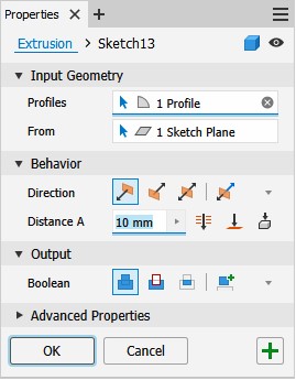
Dialogue Boxes
Inventor commands use many different dialogue boxes to obtain information to be used by the command or current operation. A typical dialogue box is shown in Figure 2-9.
The Mouse
Inventor is programed to use the three buttons on the mouse as follows:
Left Button: This is the pick button. Use it to pick objects, pick menu items, or select locations on the sketch or model.
Middle Button: The middle button or the wheel is used to zoom and pan around the Graphic window. This will be discussed in detail in Module 3.
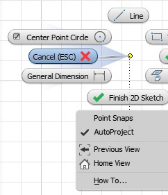
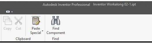
Right Button: The right button displays the Right-click menu. See Figure 2-10. The Right-click menu will change depending on the current command or operation being preformed. It is a very helpful menu and should be used as often as possible when working in Inventor.
Inventor Commands
An Inventor command is an instruction from you to Inventor instructing it what operation to perform. Commands can be entered by selecting an item from a Pull-down menu, a Right-click menu, an icon on a Toolbar, an item on the Panel menu, or entering a shortcut on the keyboard. Since there are usually many different ways of entering the same command, you should select the method that works the best for you. There is no right or wrong way to enter a command. You should experiment to find the fastest method to improve your drawing speed and productivity.
Ending the Current Command
When you enter a command, it becomes the current command or sometimes called the active command. Inventor must be instructed to end the current command. There are two methods available to do this. The first is to press the Esc key on the keyboard and the second is click to Done or Cancel on the Right-click menu as shown in Figure 2-10.
Undo and Redo Commands
In the current file, any Inventor command or commands can be undone to reverse any changes that they may have made. To do this, click the Undo icon in the Quick Access toolbar as shown in Figure 2-11. Each click will undo the previous step. If the Undo icon was used to undo a command or a series of commands, it can be reversed by clicking the Redo icon. See Figure 2-12.


WORK ALONG: Creating and Saving a Part File
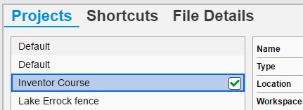
Step 1
Start Inventor and check the current project. If required, set it to Inventor Course. (Figure Step 1)
Step 2
Click the NEW command icon in the upper left corner of the screen or under the File tab. In the Create New File dialogue box, enable the folder: Templates – English. (Figure Step 2A and 2B)

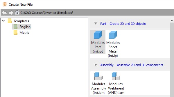
Step 3
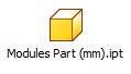
Select the template: Modules Part (in).ipt icon and click OK. (Figure Step 3)

Step 4
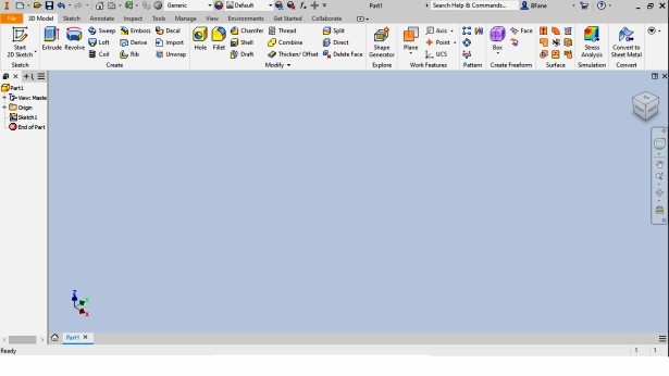
Inventor will display the Graphic window, in Sketch mode, as shown in the figure. (Figure Step 4)
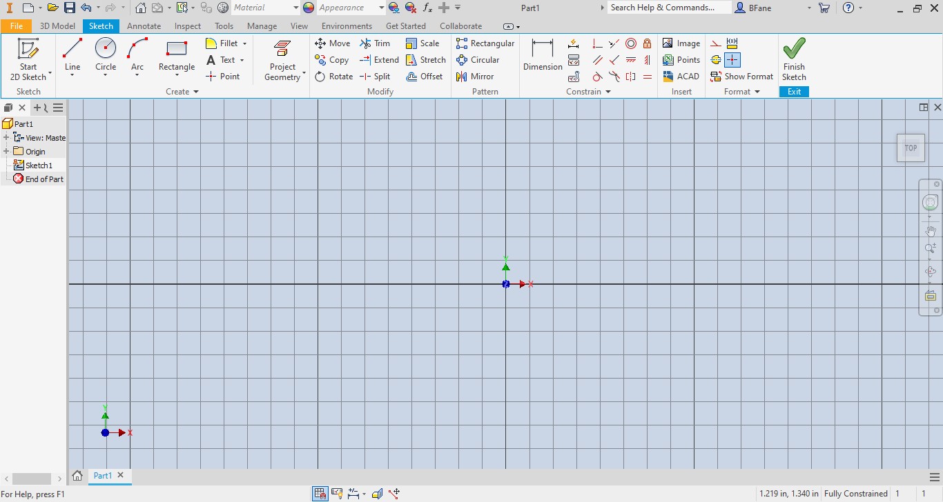
Step 5
Click the Finish Sketch icon to change to Model mode. (Figure Step 5A and 5B)
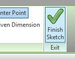

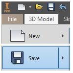
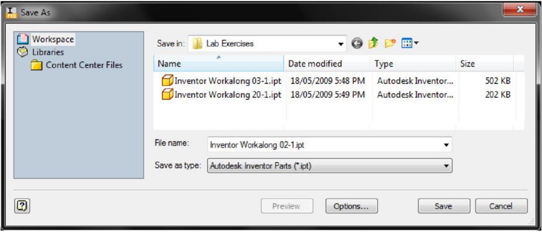
Step 6
Click the Save icon. It will open the Save As dialogue box. In the File name: box, enter the name: Inventor Workalong 02-1 and click Save. (Figure Step 6A and 6B)
Step 7
The file name should now display on top bar of the Graphic window similar to what is shown in the figure. (Figure Step 7)
Step 8
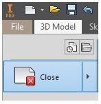
Click the File tab and then the Close icon to close the current part file. (Figure Step 8)
Step 9
Click the Inventor icon to pull down the menu. On the Pull-down menu, click Exit Autodesk Inventor Professional to exit Inventor. (Figure Step 9)
WORK ALONG: Configuring and Working with Inventor’s Interface
Step 1
Start Inventor and check the current project. If required, set it to Inventor Course.
Step 2
Click the New icon. In the New File dialogue box, enable the folder: Metric Templates.
Step 3
Select the template: Module Part (mm).ipt. (Figure Step 3)
Step 4
Click Finish Sketch to exit Sketch mode. While in Model mode, save the part file with the name: Inventor Workalong 02-2. (Figure Step 4)
Step 5
Move the cursor onto the space between the plus (+) sign and the magnifying glass at the top of the Browser bar and press and hold the left mouse button down. While holding the button down, drag the Browser bar into the Graphic window. The Graphic window should appear similar to the figure. (Figure Step 5)
Step 6
Move the cursor onto the space between the plus (+) sign and the magnifying glass at the top of the Browser bar and press and hold the left mouse button down. While holding the button down, drag the Browser bar to the left until its colors fade. Release the left mouse button and the browser bar will dock on the left edge of the screen. (Figure Step 6)

MUST KNOW: Either the Esc key on the keyboard or the Cancel on the Right-click menu must be used to end the current command. You must always let Inventor know when to terminate the current command.
Step 7
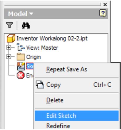
Click Sketch1 in the Browser bar to select it and right click the mouse. In the Right-click menu, click Edit Sketch. (Figure Step 7)
Step 8
The Graphic window will change to Sketch mode and should appear similar to the figure. (Figure step 8)

Step 9
Change to Model mode. Save and close the part file.
MUST KNOW: The Browser bar displays the hierarchical structure of the model or assembly of the current file. It is your most important and most-used tool to create and modify files.
Key Principles
Key Principles in Module 2
- When a file is active, Inventor will display the Graphic window. The Graphic window has two different modes, the Sketch mode and the Model mode. They are used to create 3D solid models, called
- A part file is one 3D solid model. A part file has the file extension .ipt. The file extension .ipt is an acronym for Inventor ParT. Working drawings can be created from the part file or part of an assembly or presentation file.
- Every new Inventor file must be created from an existing template
- Inventor keeps the current file in RAM memory. If the computer cashes or the power fails, all the work on the file, since the last time it was saved, will be lost. When the file is saved, Inventor saves what is in RAM memory onto the disk drive. Ensure that the current file is saved frequently to avoid losing production Saving it every 5 to 10 minutes is a good habit to get into.
- The Browser bar displays current file’s hierarchical
- The Status bar, located across the bottom of the Graphic window, is a very important part of the operator’s day-to-day work in Inventor.
- Inventor must be instructed to end the current command. There are two methods available to do this. The first is to press the Esc key on the keyboard and the second is to click Cancel or Done on the right-click menu.