2.1: Module 7 Extruding – Part 2
- Page ID
- 19871

\( \newcommand{\vecs}[1]{\overset { \scriptstyle \rightharpoonup} {\mathbf{#1}} } \)
\( \newcommand{\vecd}[1]{\overset{-\!-\!\rightharpoonup}{\vphantom{a}\smash {#1}}} \)
\( \newcommand{\id}{\mathrm{id}}\) \( \newcommand{\Span}{\mathrm{span}}\)
( \newcommand{\kernel}{\mathrm{null}\,}\) \( \newcommand{\range}{\mathrm{range}\,}\)
\( \newcommand{\RealPart}{\mathrm{Re}}\) \( \newcommand{\ImaginaryPart}{\mathrm{Im}}\)
\( \newcommand{\Argument}{\mathrm{Arg}}\) \( \newcommand{\norm}[1]{\| #1 \|}\)
\( \newcommand{\inner}[2]{\langle #1, #2 \rangle}\)
\( \newcommand{\Span}{\mathrm{span}}\)
\( \newcommand{\id}{\mathrm{id}}\)
\( \newcommand{\Span}{\mathrm{span}}\)
\( \newcommand{\kernel}{\mathrm{null}\,}\)
\( \newcommand{\range}{\mathrm{range}\,}\)
\( \newcommand{\RealPart}{\mathrm{Re}}\)
\( \newcommand{\ImaginaryPart}{\mathrm{Im}}\)
\( \newcommand{\Argument}{\mathrm{Arg}}\)
\( \newcommand{\norm}[1]{\| #1 \|}\)
\( \newcommand{\inner}[2]{\langle #1, #2 \rangle}\)
\( \newcommand{\Span}{\mathrm{span}}\) \( \newcommand{\AA}{\unicode[.8,0]{x212B}}\)
\( \newcommand{\vectorA}[1]{\vec{#1}} % arrow\)
\( \newcommand{\vectorAt}[1]{\vec{\text{#1}}} % arrow\)
\( \newcommand{\vectorB}[1]{\overset { \scriptstyle \rightharpoonup} {\mathbf{#1}} } \)
\( \newcommand{\vectorC}[1]{\textbf{#1}} \)
\( \newcommand{\vectorD}[1]{\overrightarrow{#1}} \)
\( \newcommand{\vectorDt}[1]{\overrightarrow{\text{#1}}} \)
\( \newcommand{\vectE}[1]{\overset{-\!-\!\rightharpoonup}{\vphantom{a}\smash{\mathbf {#1}}}} \)
\( \newcommand{\vecs}[1]{\overset { \scriptstyle \rightharpoonup} {\mathbf{#1}} } \)
\( \newcommand{\vecd}[1]{\overset{-\!-\!\rightharpoonup}{\vphantom{a}\smash {#1}}} \)
\(\newcommand{\avec}{\mathbf a}\) \(\newcommand{\bvec}{\mathbf b}\) \(\newcommand{\cvec}{\mathbf c}\) \(\newcommand{\dvec}{\mathbf d}\) \(\newcommand{\dtil}{\widetilde{\mathbf d}}\) \(\newcommand{\evec}{\mathbf e}\) \(\newcommand{\fvec}{\mathbf f}\) \(\newcommand{\nvec}{\mathbf n}\) \(\newcommand{\pvec}{\mathbf p}\) \(\newcommand{\qvec}{\mathbf q}\) \(\newcommand{\svec}{\mathbf s}\) \(\newcommand{\tvec}{\mathbf t}\) \(\newcommand{\uvec}{\mathbf u}\) \(\newcommand{\vvec}{\mathbf v}\) \(\newcommand{\wvec}{\mathbf w}\) \(\newcommand{\xvec}{\mathbf x}\) \(\newcommand{\yvec}{\mathbf y}\) \(\newcommand{\zvec}{\mathbf z}\) \(\newcommand{\rvec}{\mathbf r}\) \(\newcommand{\mvec}{\mathbf m}\) \(\newcommand{\zerovec}{\mathbf 0}\) \(\newcommand{\onevec}{\mathbf 1}\) \(\newcommand{\real}{\mathbb R}\) \(\newcommand{\twovec}[2]{\left[\begin{array}{r}#1 \\ #2 \end{array}\right]}\) \(\newcommand{\ctwovec}[2]{\left[\begin{array}{c}#1 \\ #2 \end{array}\right]}\) \(\newcommand{\threevec}[3]{\left[\begin{array}{r}#1 \\ #2 \\ #3 \end{array}\right]}\) \(\newcommand{\cthreevec}[3]{\left[\begin{array}{c}#1 \\ #2 \\ #3 \end{array}\right]}\) \(\newcommand{\fourvec}[4]{\left[\begin{array}{r}#1 \\ #2 \\ #3 \\ #4 \end{array}\right]}\) \(\newcommand{\cfourvec}[4]{\left[\begin{array}{c}#1 \\ #2 \\ #3 \\ #4 \end{array}\right]}\) \(\newcommand{\fivevec}[5]{\left[\begin{array}{r}#1 \\ #2 \\ #3 \\ #4 \\ #5 \\ \end{array}\right]}\) \(\newcommand{\cfivevec}[5]{\left[\begin{array}{c}#1 \\ #2 \\ #3 \\ #4 \\ #5 \\ \end{array}\right]}\) \(\newcommand{\mattwo}[4]{\left[\begin{array}{rr}#1 \amp #2 \\ #3 \amp #4 \\ \end{array}\right]}\) \(\newcommand{\laspan}[1]{\text{Span}\{#1\}}\) \(\newcommand{\bcal}{\cal B}\) \(\newcommand{\ccal}{\cal C}\) \(\newcommand{\scal}{\cal S}\) \(\newcommand{\wcal}{\cal W}\) \(\newcommand{\ecal}{\cal E}\) \(\newcommand{\coords}[2]{\left\{#1\right\}_{#2}}\) \(\newcommand{\gray}[1]{\color{gray}{#1}}\) \(\newcommand{\lgray}[1]{\color{lightgray}{#1}}\) \(\newcommand{\rank}{\operatorname{rank}}\) \(\newcommand{\row}{\text{Row}}\) \(\newcommand{\col}{\text{Col}}\) \(\renewcommand{\row}{\text{Row}}\) \(\newcommand{\nul}{\text{Nul}}\) \(\newcommand{\var}{\text{Var}}\) \(\newcommand{\corr}{\text{corr}}\) \(\newcommand{\len}[1]{\left|#1\right|}\) \(\newcommand{\bbar}{\overline{\bvec}}\) \(\newcommand{\bhat}{\widehat{\bvec}}\) \(\newcommand{\bperp}{\bvec^\perp}\) \(\newcommand{\xhat}{\widehat{\xvec}}\) \(\newcommand{\vhat}{\widehat{\vvec}}\) \(\newcommand{\uhat}{\widehat{\uvec}}\) \(\newcommand{\what}{\widehat{\wvec}}\) \(\newcommand{\Sighat}{\widehat{\Sigma}}\) \(\newcommand{\lt}{<}\) \(\newcommand{\gt}{>}\) \(\newcommand{\amp}{&}\) \(\definecolor{fillinmathshade}{gray}{0.9}\)7
Module 7 Extruding – Part 2
Wally Baumback
Learning Outcomes
When you have completed this module, you will be able to:
- Describe how to construct a solid model using multiple sketches, linear dimensions, plus joining and cutting extrusions.
- Describe and apply the 2DSKETCH command to create 2D sketches on a solid model. Extrude the sketches to either join them to or cut them from the solid model.
Point to Point Linear Dimensions
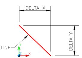
A point to point linear dimension is a dimension measuring the delta X or the delta Y distance between two points of an existing object or objects. The points, which are normally the endpoints of a line, could also be centre points of circles or arcs as you will see in future modules. If the points both lie on the same X or Y axis, the dimension can only inserted in one direction. If the points do not lie on the same axis, you have the choice of inserting either the delta X or the delta Y dimension. See Figure 7-1. The three steps used to insert a point to point linear dimension are shown below.
Linear Dimensions Applied To an Inclined Line
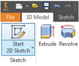
Inventor Command: 2D SKETCH
The 2D SKETCH command is used to create a 2D sketch on a sketching plane or onto an existing 3D solid model.
Shortcut: S
WORK ALONG: Constructing a Solid Model Using Multiple Sketches
Step 1
Check the default project and if necessary, set it to Inventor Course.
Step 2
Enter the NEW command to start a new part file using the template: Metric-Modules Part (mm).ipt.
Step 3
Save the file with the name: Inventor Workalong 07-1. (Figure Step 3A and 3B)
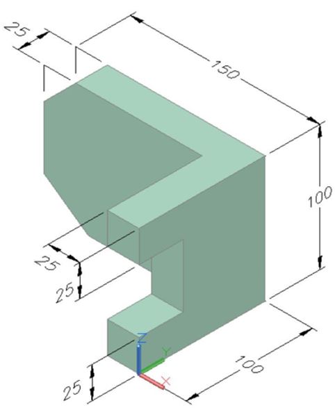
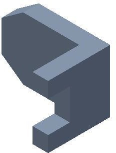
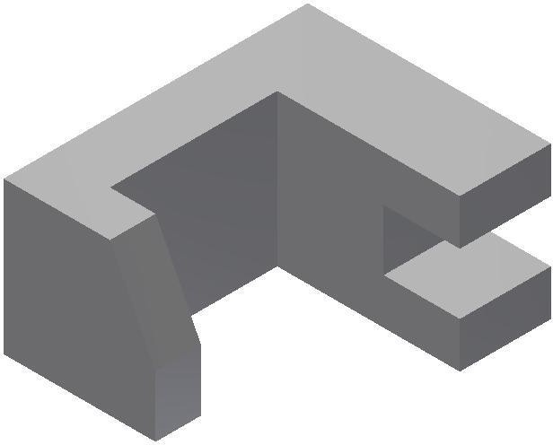
Solid Model – Home View
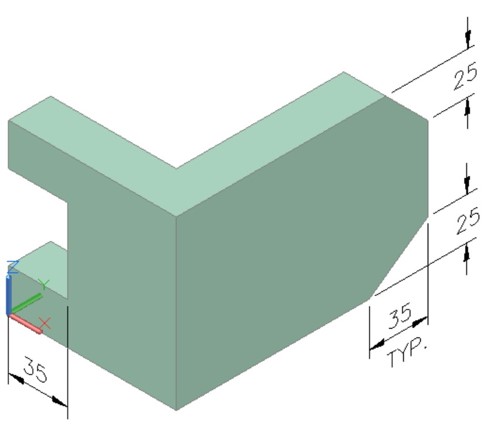
Solid Model – Rotated View
Step 4
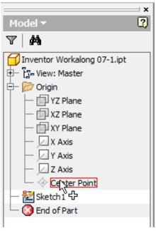
Edit Sketch 1 and enter the PROJECT GEOMETRY command and project the Center Point onto the sketching plane. Press Esc to exit the command. (Figure Step 4)
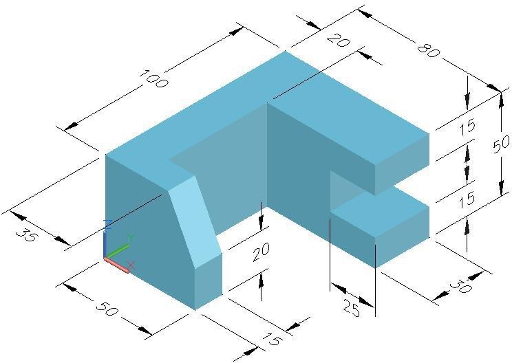
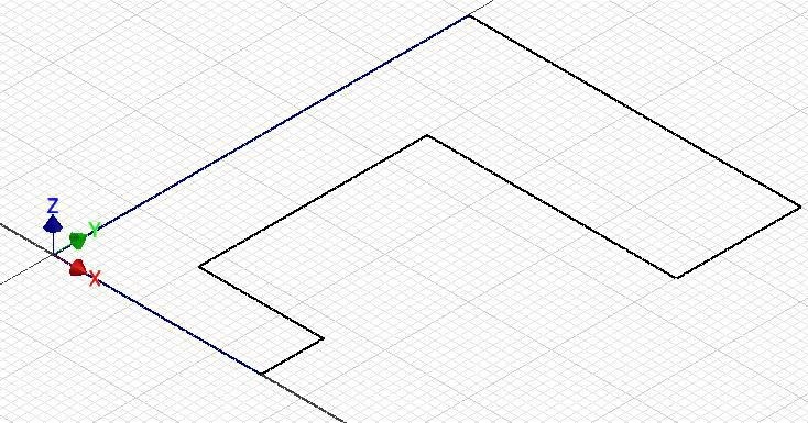
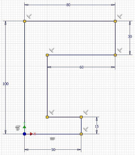
Step 5
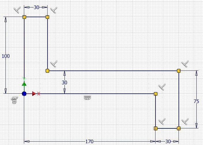
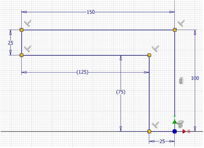
Draw the Top view of the model starting at X0Y0Z0. This is the Base sketch. (Figure Step 5)
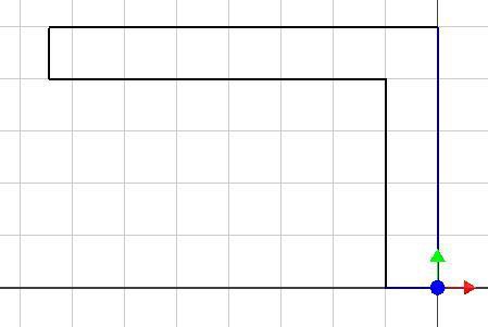
Step 6
Add 4 driving dimensions to fully constrain the sketch. Add 2 driven dimensions.
Step 7
Press F8 to display the constraints. (Figure Step 7)
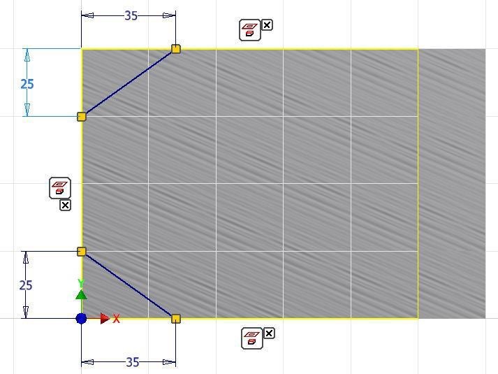
Step 8
The sketch should now be fully constrained and all the lines display purple on a black background. (Figure Step 8)

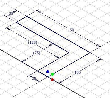
Step 9
Press F6 to change the view to the Home view. Click the FINISH SKETCH command to return to Model mode. (Figure Step 9)
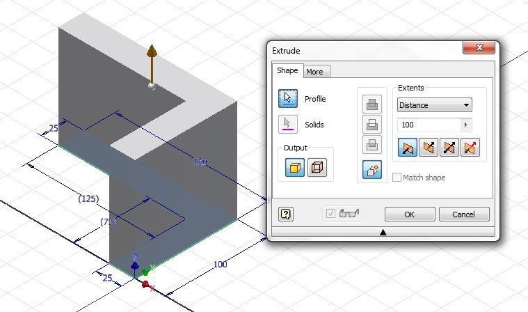
Step 10
Enter E to execute the EXTRUDE command and extrude the model 100 mm in the positive Z direction. (Figure Step 10)
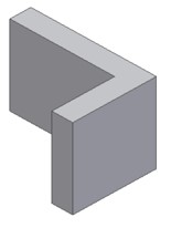
Step 11
The solid model should appear as shown in the figure. (Figure Step 11)
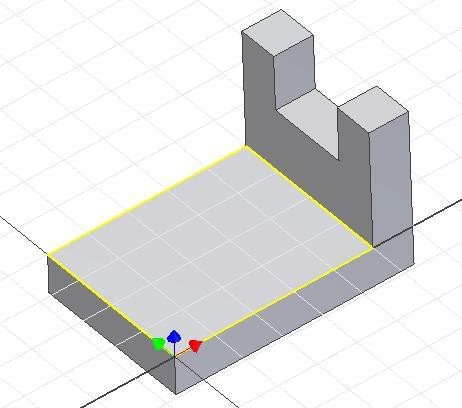
Step 12
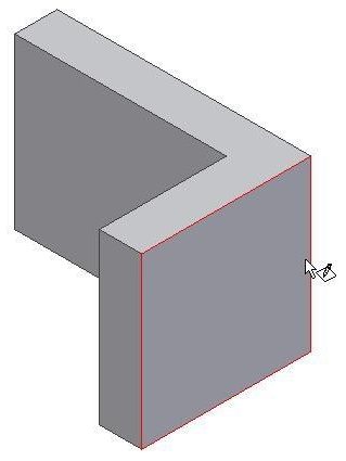
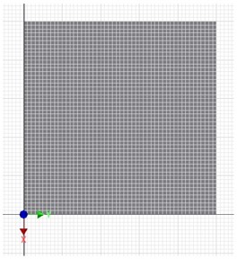
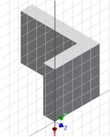
Click the 2D SKETCH icon and when prompted, select the right side plane as shown in the figure. Exit the command and the grid will display on the plane in Sketch mode. Press F6 to change to the Home view. (Figure Step 12A, 12B, and 12C)
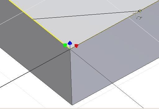
Step 13
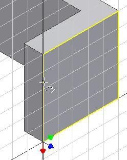
Enter L for the LINE command and start the first endpoint of the line by snapping onto the plane edge line. (Figure Step 13)
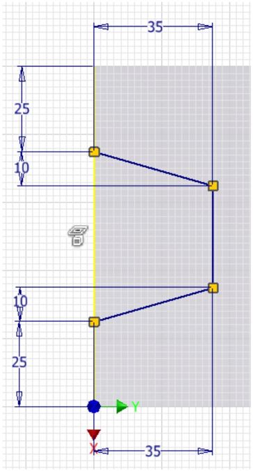
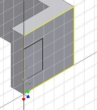
Step 14
Draw three lines, applying perpendicular geometrical constraints and snapping back onto the edge. Guess at the length of the lines making them approximately the correct length. (Figure Step 14)
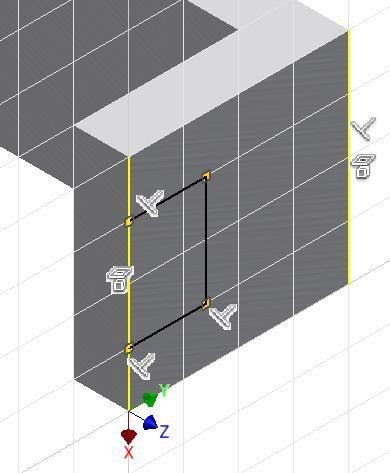
Step 15
Press F8 to display the constraint icons. (Figure Step 15)
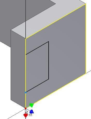
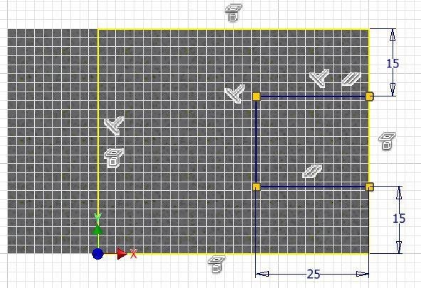
Step 16
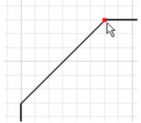
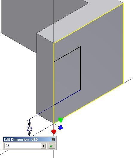
Enter D for the GENERAL DIMENSION command. Move the cursor to bottom corner of the model. When a small point highlights, click the mouse. (Figure Step 16)
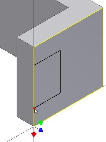
Step 17
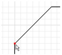
For the second point of the dimension, click the end of the line as shown in the figure. Locate and set the dimension to 25. (Figure Step 17A and 17B)
Step 18
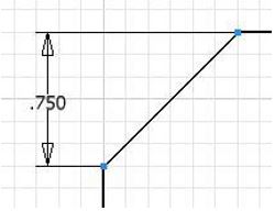
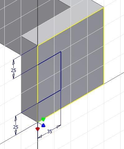
Add two additional dimensions to fully constrain it. (Figure Step 18A, 18B, and 18C)

Step 19
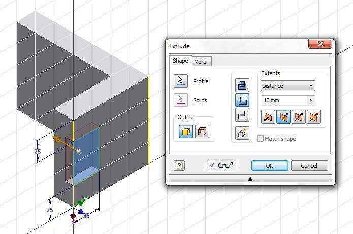
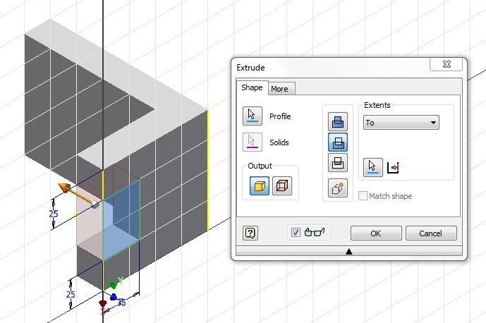
Enter E for the EXTRUDE command. (Figure Step 19)
Step 20
Set the Extents to To, the type to Cut and select the back face to locate where to extrude to. (Figure Step 20)
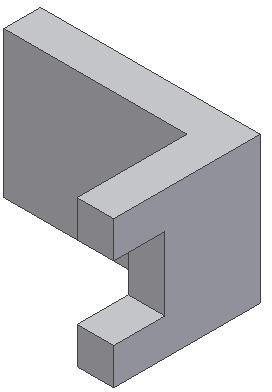
Step 21
Your model should appear as shown in the figure. (Figure Step 21)
Step 22
Click the 2D Sketch icon and select the top plane to start a new sketch. Orbit the model to match the figure. (Figure Step 22)
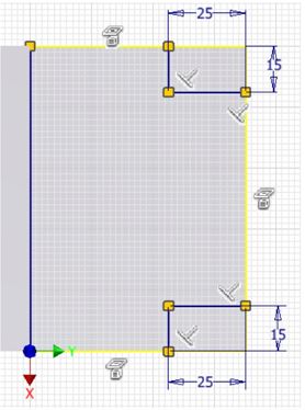
Step 23
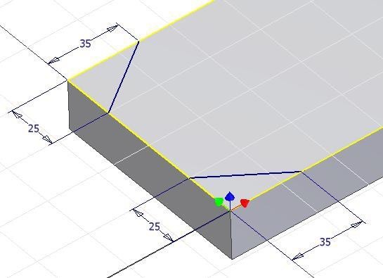
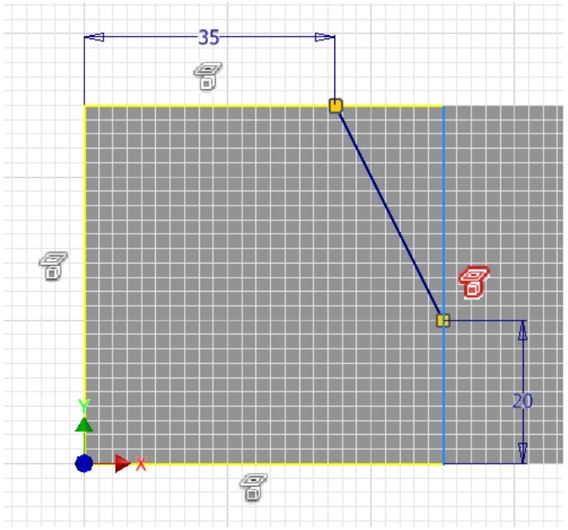
On the sketch, draw a line across the corner. Make sure that you snap both ends of the line to the edges. Guess at the distance from the corner. (Figure Step 23)
Step 24
Draw a line on the opposite side and dimension both lines using four point to point dimensions. (Figure Step 24)
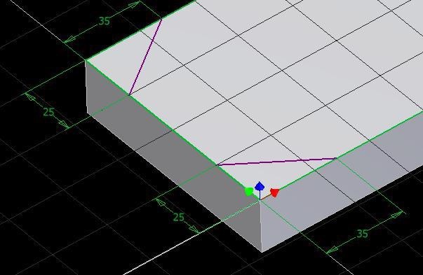
Step 25
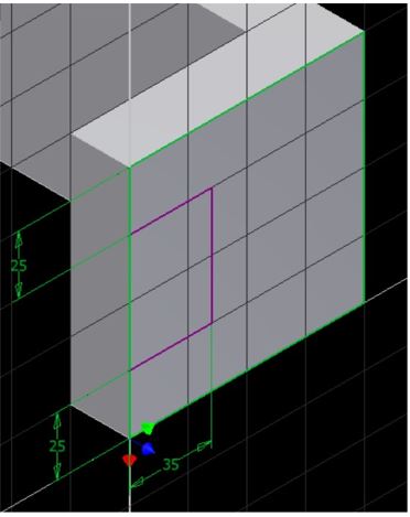
Your sketch should be fully constrained as shown in the figure. (Figure Step 25)
Step 26
Press F8 to display the constraint icons. (Figure Step 26)
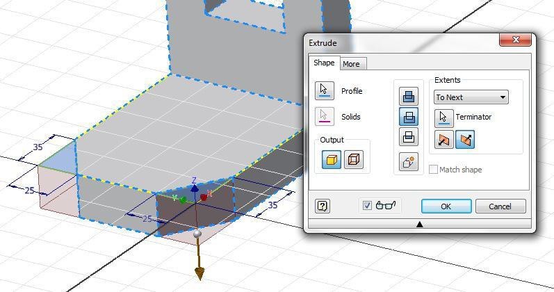
Step 27
Extrude the sketch using the To Next extents. Select the two profiles to extrude and ensure that you enable the Cut icon. (Figure Step 27)
Step 28
Change to the Home view by pressing F6. Change the colour of the completed model to color: Light Steel Blue. (Figure Step 28)
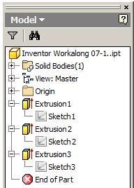
Step 29
Expand the Browser bar. You can see that the model hierarchy shows the three sketches and an extrusion of each one. (Figure Step 29)
Step 30
Save and close the file.
Key Principles
Key Principles in Module 7
- A point to point linear dimension is a dimension measuring the delta X or the delta Y distance between two points of an existing object or objects.
- The 2D SKETCH command is used to create a 2D sketch on a sketching plane or onto an existing 3D solid model.Lab Exercise 7.1
Lab Exercise 7-1
Time allowed: 45 minutes.
| Part Name | Project | Units | Template | Color | Material |
| Inventor Lab 07-1 | Inventor Course | Millimeters | Metric-Modules Part (mm).ipt | Steel | N/A |
Step 1
Project the Center Point onto the sketching plane.
Step 2
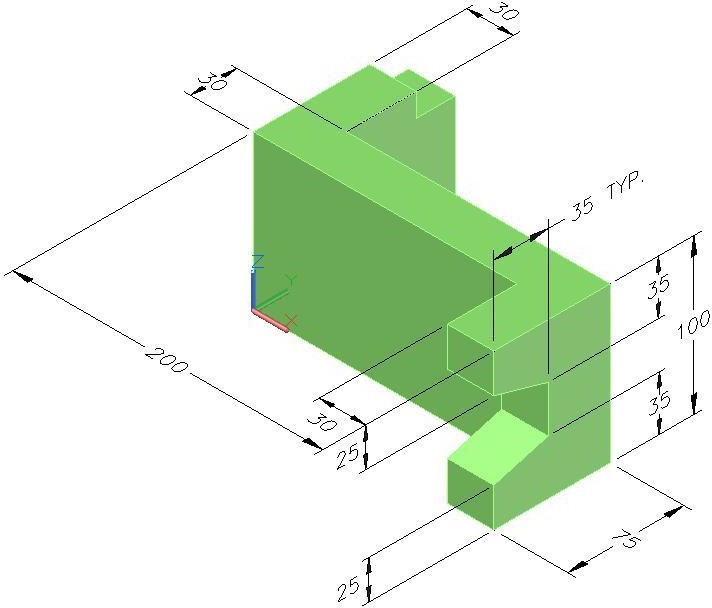
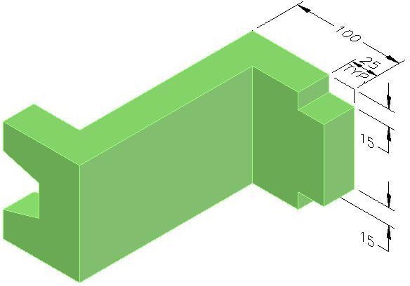
Note the location of X0Y0Z0. Draw the necessary sketches and extrude them to produced the solid model. Apply all of the necessary geometrical and dimensional constraints to fully constrain all sketches. (Figure Step 2A and 2B)
3D Model
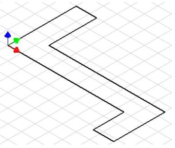
Suggested Base Sketch
Step 3
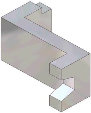
Apply the colour shown above. (Figure Step 3)
Completed Solid Model – Home View
AUTHOR’S GEOMETRIC CONSTRAINS: The following three figures shows the base and additional sketch’s construction method plus geometric and dimensional constraints suggested by the author to help you learn how to construct and constrain sketches. It is only the suggested method and if you can complete a fully constrained sketches using different construction methods and constraints, that is what is important. You may want to compare your construction method and constraints used with the authors.
Lab Exercise 7-2
Time allowed: 45 minutes.
| Part Name | Project | Units | Template | Color | Material |
| Inventor Lab 07-2 | Inventor Course | Millimeters | Metric-Modules Part (mm).ipt | Chrome – Polished | N/A |
Step 1
Project the Center Point onto the base sketching plane.
Step 2
Note the location of X0Y0Z0. Draw the necessary sketches and extrude them to produced the solid model. Apply all of the necessary geometrical and dimensional constraints to fully constrain all sketches. (Figure Step 2A, 2B, and 2C)
3D Model – Home View
A Rotated View of the 3D Model
Suggested Base View
Step 3
Apply the colour shown above. (Figure Step 3)
Completed Solid Model – Home View
Step 4
Save the file with the name: Inventor Lab 07-2 as shown above.