2.2: Module 8 Multiview Drawings
- Page ID
- 19872

\( \newcommand{\vecs}[1]{\overset { \scriptstyle \rightharpoonup} {\mathbf{#1}} } \)
\( \newcommand{\vecd}[1]{\overset{-\!-\!\rightharpoonup}{\vphantom{a}\smash {#1}}} \)
\( \newcommand{\id}{\mathrm{id}}\) \( \newcommand{\Span}{\mathrm{span}}\)
( \newcommand{\kernel}{\mathrm{null}\,}\) \( \newcommand{\range}{\mathrm{range}\,}\)
\( \newcommand{\RealPart}{\mathrm{Re}}\) \( \newcommand{\ImaginaryPart}{\mathrm{Im}}\)
\( \newcommand{\Argument}{\mathrm{Arg}}\) \( \newcommand{\norm}[1]{\| #1 \|}\)
\( \newcommand{\inner}[2]{\langle #1, #2 \rangle}\)
\( \newcommand{\Span}{\mathrm{span}}\)
\( \newcommand{\id}{\mathrm{id}}\)
\( \newcommand{\Span}{\mathrm{span}}\)
\( \newcommand{\kernel}{\mathrm{null}\,}\)
\( \newcommand{\range}{\mathrm{range}\,}\)
\( \newcommand{\RealPart}{\mathrm{Re}}\)
\( \newcommand{\ImaginaryPart}{\mathrm{Im}}\)
\( \newcommand{\Argument}{\mathrm{Arg}}\)
\( \newcommand{\norm}[1]{\| #1 \|}\)
\( \newcommand{\inner}[2]{\langle #1, #2 \rangle}\)
\( \newcommand{\Span}{\mathrm{span}}\) \( \newcommand{\AA}{\unicode[.8,0]{x212B}}\)
\( \newcommand{\vectorA}[1]{\vec{#1}} % arrow\)
\( \newcommand{\vectorAt}[1]{\vec{\text{#1}}} % arrow\)
\( \newcommand{\vectorB}[1]{\overset { \scriptstyle \rightharpoonup} {\mathbf{#1}} } \)
\( \newcommand{\vectorC}[1]{\textbf{#1}} \)
\( \newcommand{\vectorD}[1]{\overrightarrow{#1}} \)
\( \newcommand{\vectorDt}[1]{\overrightarrow{\text{#1}}} \)
\( \newcommand{\vectE}[1]{\overset{-\!-\!\rightharpoonup}{\vphantom{a}\smash{\mathbf {#1}}}} \)
\( \newcommand{\vecs}[1]{\overset { \scriptstyle \rightharpoonup} {\mathbf{#1}} } \)
\( \newcommand{\vecd}[1]{\overset{-\!-\!\rightharpoonup}{\vphantom{a}\smash {#1}}} \)
\(\newcommand{\avec}{\mathbf a}\) \(\newcommand{\bvec}{\mathbf b}\) \(\newcommand{\cvec}{\mathbf c}\) \(\newcommand{\dvec}{\mathbf d}\) \(\newcommand{\dtil}{\widetilde{\mathbf d}}\) \(\newcommand{\evec}{\mathbf e}\) \(\newcommand{\fvec}{\mathbf f}\) \(\newcommand{\nvec}{\mathbf n}\) \(\newcommand{\pvec}{\mathbf p}\) \(\newcommand{\qvec}{\mathbf q}\) \(\newcommand{\svec}{\mathbf s}\) \(\newcommand{\tvec}{\mathbf t}\) \(\newcommand{\uvec}{\mathbf u}\) \(\newcommand{\vvec}{\mathbf v}\) \(\newcommand{\wvec}{\mathbf w}\) \(\newcommand{\xvec}{\mathbf x}\) \(\newcommand{\yvec}{\mathbf y}\) \(\newcommand{\zvec}{\mathbf z}\) \(\newcommand{\rvec}{\mathbf r}\) \(\newcommand{\mvec}{\mathbf m}\) \(\newcommand{\zerovec}{\mathbf 0}\) \(\newcommand{\onevec}{\mathbf 1}\) \(\newcommand{\real}{\mathbb R}\) \(\newcommand{\twovec}[2]{\left[\begin{array}{r}#1 \\ #2 \end{array}\right]}\) \(\newcommand{\ctwovec}[2]{\left[\begin{array}{c}#1 \\ #2 \end{array}\right]}\) \(\newcommand{\threevec}[3]{\left[\begin{array}{r}#1 \\ #2 \\ #3 \end{array}\right]}\) \(\newcommand{\cthreevec}[3]{\left[\begin{array}{c}#1 \\ #2 \\ #3 \end{array}\right]}\) \(\newcommand{\fourvec}[4]{\left[\begin{array}{r}#1 \\ #2 \\ #3 \\ #4 \end{array}\right]}\) \(\newcommand{\cfourvec}[4]{\left[\begin{array}{c}#1 \\ #2 \\ #3 \\ #4 \end{array}\right]}\) \(\newcommand{\fivevec}[5]{\left[\begin{array}{r}#1 \\ #2 \\ #3 \\ #4 \\ #5 \\ \end{array}\right]}\) \(\newcommand{\cfivevec}[5]{\left[\begin{array}{c}#1 \\ #2 \\ #3 \\ #4 \\ #5 \\ \end{array}\right]}\) \(\newcommand{\mattwo}[4]{\left[\begin{array}{rr}#1 \amp #2 \\ #3 \amp #4 \\ \end{array}\right]}\) \(\newcommand{\laspan}[1]{\text{Span}\{#1\}}\) \(\newcommand{\bcal}{\cal B}\) \(\newcommand{\ccal}{\cal C}\) \(\newcommand{\scal}{\cal S}\) \(\newcommand{\wcal}{\cal W}\) \(\newcommand{\ecal}{\cal E}\) \(\newcommand{\coords}[2]{\left\{#1\right\}_{#2}}\) \(\newcommand{\gray}[1]{\color{gray}{#1}}\) \(\newcommand{\lgray}[1]{\color{lightgray}{#1}}\) \(\newcommand{\rank}{\operatorname{rank}}\) \(\newcommand{\row}{\text{Row}}\) \(\newcommand{\col}{\text{Col}}\) \(\renewcommand{\row}{\text{Row}}\) \(\newcommand{\nul}{\text{Nul}}\) \(\newcommand{\var}{\text{Var}}\) \(\newcommand{\corr}{\text{corr}}\) \(\newcommand{\len}[1]{\left|#1\right|}\) \(\newcommand{\bbar}{\overline{\bvec}}\) \(\newcommand{\bhat}{\widehat{\bvec}}\) \(\newcommand{\bperp}{\bvec^\perp}\) \(\newcommand{\xhat}{\widehat{\xvec}}\) \(\newcommand{\vhat}{\widehat{\vvec}}\) \(\newcommand{\uhat}{\widehat{\uvec}}\) \(\newcommand{\what}{\widehat{\wvec}}\) \(\newcommand{\Sighat}{\widehat{\Sigma}}\) \(\newcommand{\lt}{<}\) \(\newcommand{\gt}{>}\) \(\newcommand{\amp}{&}\) \(\definecolor{fillinmathshade}{gray}{0.9}\)8
Module 8 Multiview Drawings
Wally Baumback
Learning Outcomes
When you have completed this module, you will be able to:
- Describe multiview drawings, the glass box principle, the three standard views, object lines, and hidden lines.
- From a 3D pictorial of an object, draw a multiview drawing using the three standard views.
NOTE: If you understand multiview drawings, object lines, hidden lines, and you can draw the three standard views of an object, skip this module.
Multiview Drawing
The drafting and design world uses a system of representing a three- dimensional object by drawing two-dimensional views. It is called a multiview drawing. To explain this system of drawing, the object shown in Figure 8-1 will be used in this module. To draw a two-dimensional view of one side of the object, place a imaginary plane parallel to the side and project the view of the object perpendicular onto the plane. This is called orthographic projection. Imagine the plane to a sheet of glass. See Figure 8-2.

The 3D Model
Projecting the
Two-Dimensional View
The Glass Box Principle
To carry this principal further, place a plane on each side of the object for a total of six planes or sheets of glass to form a glass box. This is called the Glass Box Principle, see Figure 8-3. Picture unfolding the glass box onto a flat two-dimensional plane as shown in Figure 8-4. All six views are now visible at the same time.
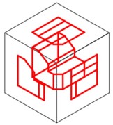
The Glass Box Principle
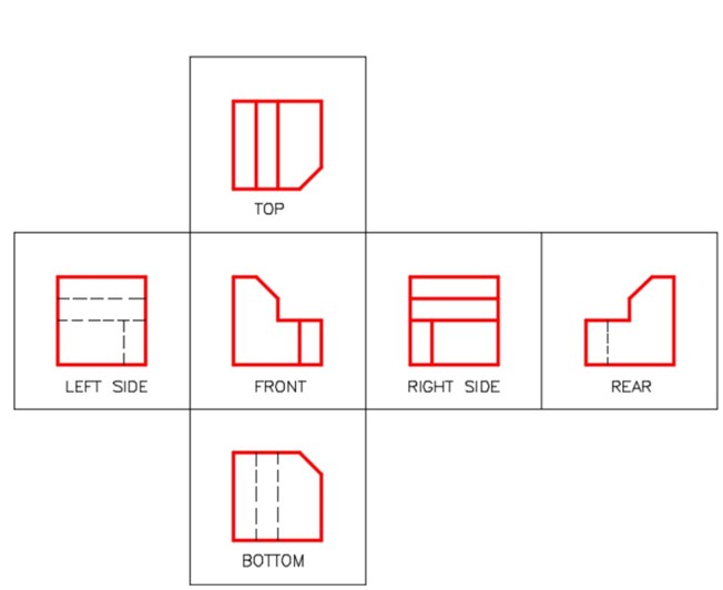
The Glass Box Unfolded [Click to see image full size]
The Three Standard Views
In almost all objects, three views are adequate to describe it. In fact, there are many objects that only need two views and some that only need one view to describe it. The six views are Top, Front, Right Side, Left Side, Rear, and Bottom. The three standard views are the Top, Front, and Right Side. They must be drawn in the positions shown in Figure 8-5 and they must be aligned.
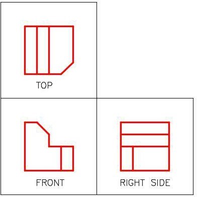
The Three Standard Views
Picking the Standard Three Views
The three standard views are always selected as shown in Figure 8-6.
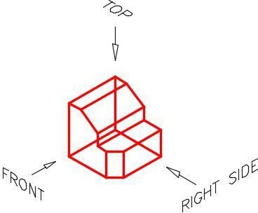
Picking the Three Standard Views
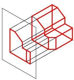
Drawing the Views
Usually it is best to draw the view with the most irregular shape first and then project lines to the other two views. For the object in Figure 8-7, the front view should be drawn first and then the top and right side views are projected. Notice how the views have to align. Figure 8-7 shows two different methods of projecting lines from the top view to the right side view or vise versa. The distance between the views is not important.
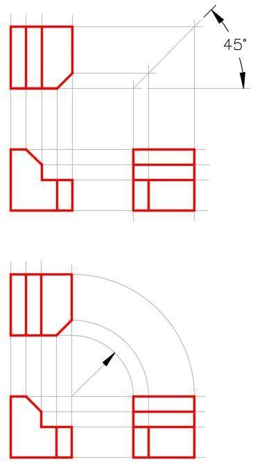
Two Methods for View Layout and Alignment
Drafting Lesson Object and Hidden Lines
Lines and features that can be seen in the views are drawn with continuous or solid lines. They are called object lines. Even though they are called object lines, they can be circular in shape. To completely describe an object in a multiview drawing, the drafter must also show all lines or features that are hidden in that view. They are called hidden lines and their linetype is dashed. Study the multiview drawing below and take note how the holes going through the object are shown with hidden lines. See Figures 8-8 and 8-9.
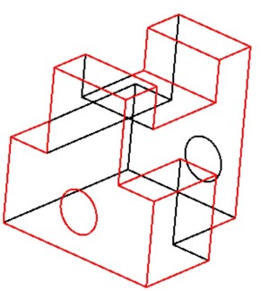
The Model
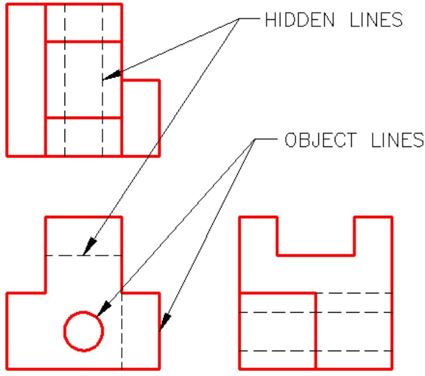
The Multiview Drawing of the Model
Key Principles
Key Principles in Module 8
- The drafting and design world uses a system of representing a three-dimensional object by drawing two-dimensional This is called a multiview drawing.
- The three standard views of a multiview drawing are the Top, Front, and Right Side.
- When drawing a multiview drawing, the three standard views of an object must be drawn in the correct position and must be aligned. The distance between the views is not important.
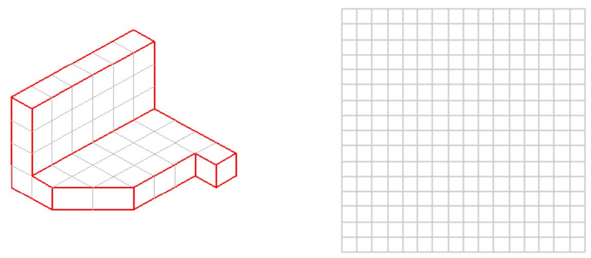
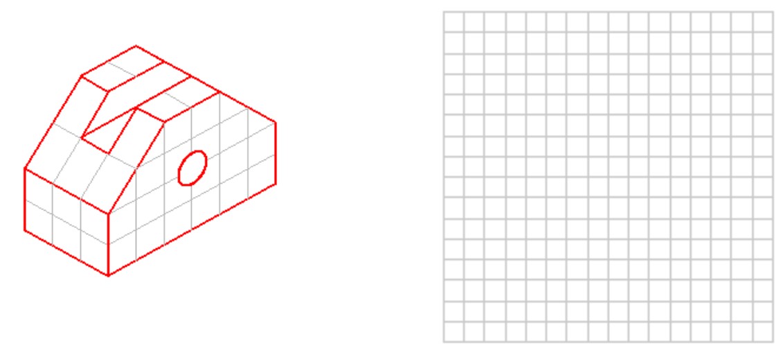
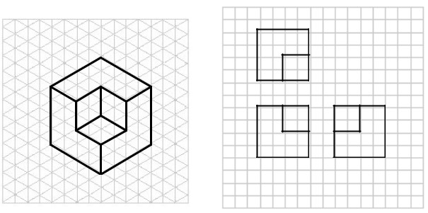
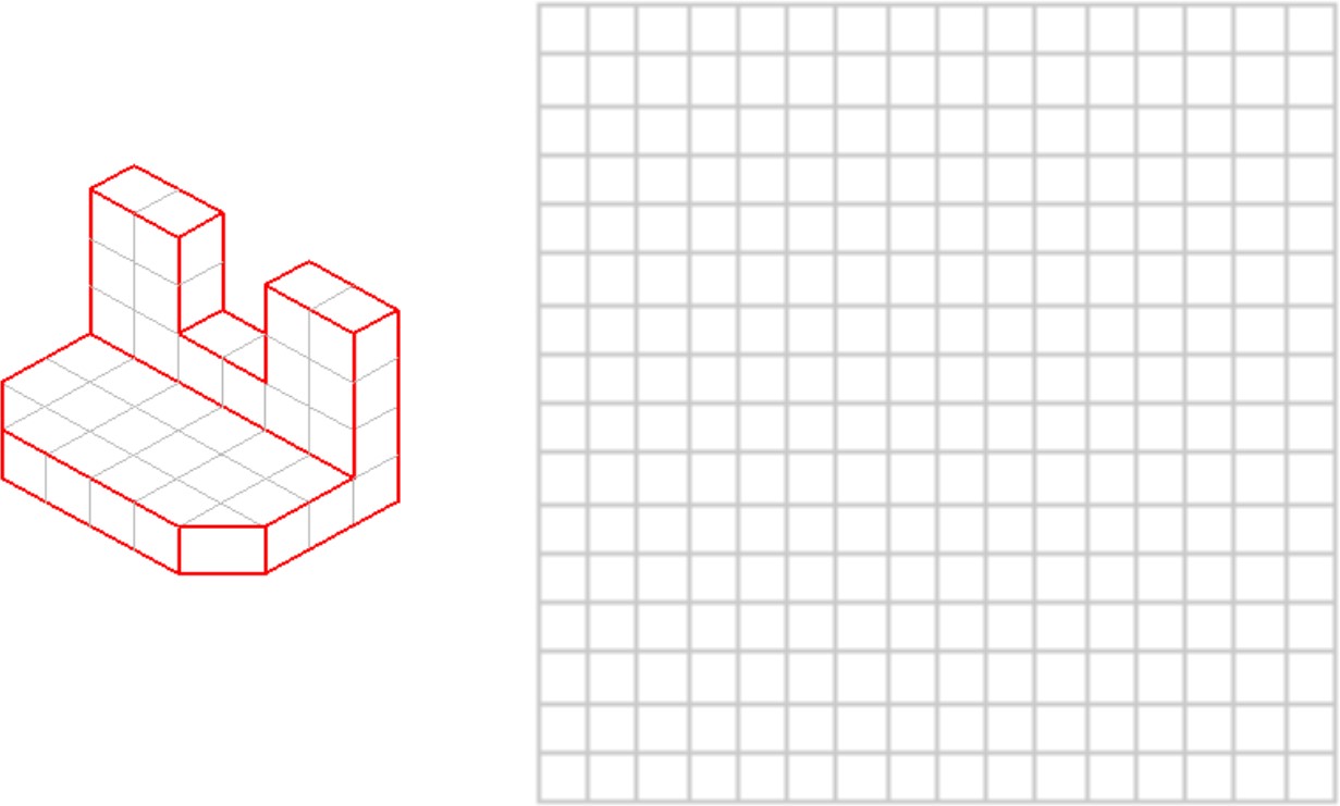
Lab Exercise 8-1
Time allowed: 15 minutes.
Step 1
Sketch the Top, Front and Right Side views of the Object 8-1.
Step 2
Use one grid on the model equal to one grid on the drawing. See the example.
Step 3
When complete, check your answers at the end of this chapter.
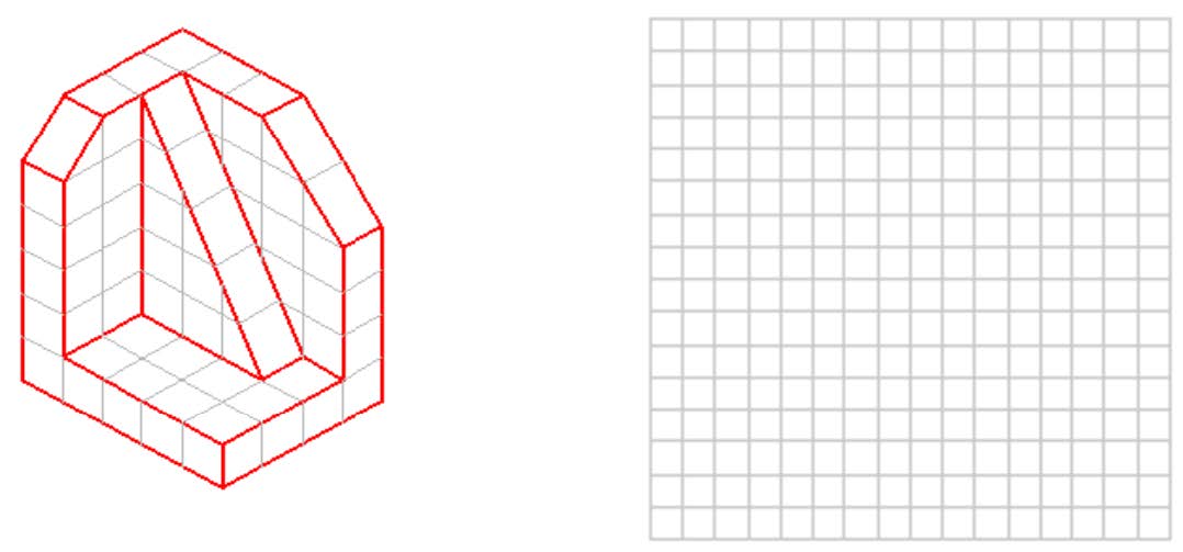
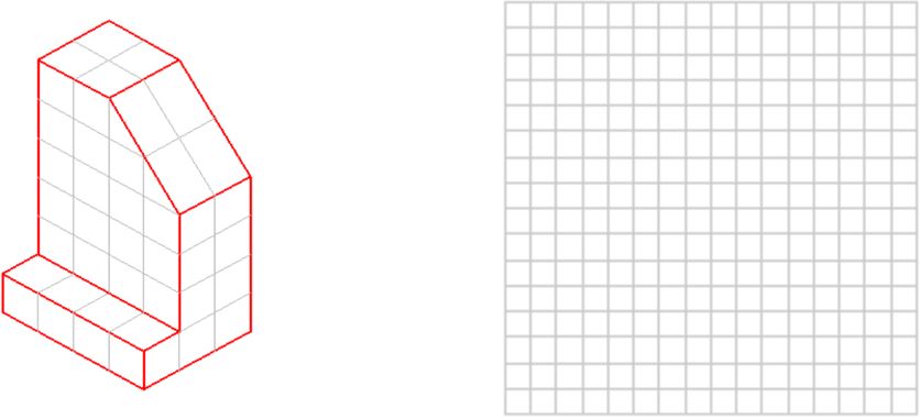
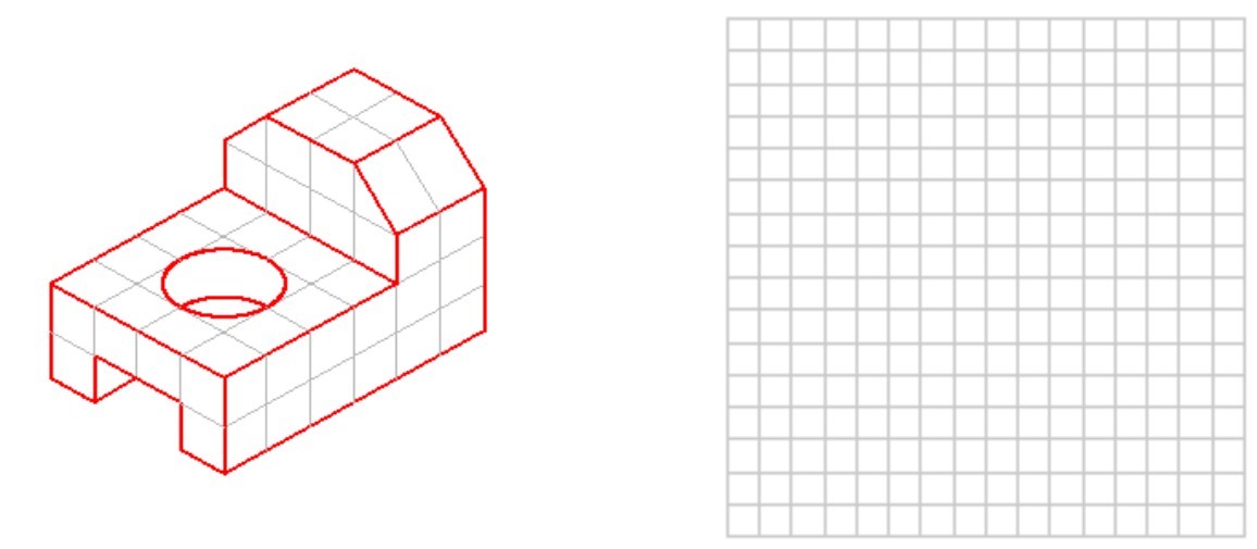
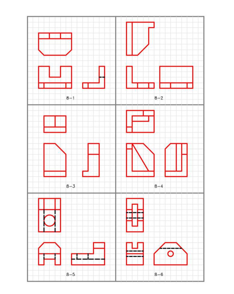
Lab Exercise 8-2
Time allowed: 60 minutes.
Step 1
Sketch the Top, Front, and Right Side views of each model.
Step 2
Use one grid on the model equal to one grid on the drawing.
Step 3
Check your answers at the end of this chapter. Do not look at the answers until you have completed your sketch.