
5.2: Module 23 Presentation Files
- Page ID
- 19888

\( \newcommand{\vecs}[1]{\overset { \scriptstyle \rightharpoonup} {\mathbf{#1}} } \)
\( \newcommand{\vecd}[1]{\overset{-\!-\!\rightharpoonup}{\vphantom{a}\smash {#1}}} \)
\( \newcommand{\id}{\mathrm{id}}\) \( \newcommand{\Span}{\mathrm{span}}\)
( \newcommand{\kernel}{\mathrm{null}\,}\) \( \newcommand{\range}{\mathrm{range}\,}\)
\( \newcommand{\RealPart}{\mathrm{Re}}\) \( \newcommand{\ImaginaryPart}{\mathrm{Im}}\)
\( \newcommand{\Argument}{\mathrm{Arg}}\) \( \newcommand{\norm}[1]{\| #1 \|}\)
\( \newcommand{\inner}[2]{\langle #1, #2 \rangle}\)
\( \newcommand{\Span}{\mathrm{span}}\)
\( \newcommand{\id}{\mathrm{id}}\)
\( \newcommand{\Span}{\mathrm{span}}\)
\( \newcommand{\kernel}{\mathrm{null}\,}\)
\( \newcommand{\range}{\mathrm{range}\,}\)
\( \newcommand{\RealPart}{\mathrm{Re}}\)
\( \newcommand{\ImaginaryPart}{\mathrm{Im}}\)
\( \newcommand{\Argument}{\mathrm{Arg}}\)
\( \newcommand{\norm}[1]{\| #1 \|}\)
\( \newcommand{\inner}[2]{\langle #1, #2 \rangle}\)
\( \newcommand{\Span}{\mathrm{span}}\) \( \newcommand{\AA}{\unicode[.8,0]{x212B}}\)
\( \newcommand{\vectorA}[1]{\vec{#1}} % arrow\)
\( \newcommand{\vectorAt}[1]{\vec{\text{#1}}} % arrow\)
\( \newcommand{\vectorB}[1]{\overset { \scriptstyle \rightharpoonup} {\mathbf{#1}} } \)
\( \newcommand{\vectorC}[1]{\textbf{#1}} \)
\( \newcommand{\vectorD}[1]{\overrightarrow{#1}} \)
\( \newcommand{\vectorDt}[1]{\overrightarrow{\text{#1}}} \)
\( \newcommand{\vectE}[1]{\overset{-\!-\!\rightharpoonup}{\vphantom{a}\smash{\mathbf {#1}}}} \)
\( \newcommand{\vecs}[1]{\overset { \scriptstyle \rightharpoonup} {\mathbf{#1}} } \)
\( \newcommand{\vecd}[1]{\overset{-\!-\!\rightharpoonup}{\vphantom{a}\smash {#1}}} \)
\(\newcommand{\avec}{\mathbf a}\) \(\newcommand{\bvec}{\mathbf b}\) \(\newcommand{\cvec}{\mathbf c}\) \(\newcommand{\dvec}{\mathbf d}\) \(\newcommand{\dtil}{\widetilde{\mathbf d}}\) \(\newcommand{\evec}{\mathbf e}\) \(\newcommand{\fvec}{\mathbf f}\) \(\newcommand{\nvec}{\mathbf n}\) \(\newcommand{\pvec}{\mathbf p}\) \(\newcommand{\qvec}{\mathbf q}\) \(\newcommand{\svec}{\mathbf s}\) \(\newcommand{\tvec}{\mathbf t}\) \(\newcommand{\uvec}{\mathbf u}\) \(\newcommand{\vvec}{\mathbf v}\) \(\newcommand{\wvec}{\mathbf w}\) \(\newcommand{\xvec}{\mathbf x}\) \(\newcommand{\yvec}{\mathbf y}\) \(\newcommand{\zvec}{\mathbf z}\) \(\newcommand{\rvec}{\mathbf r}\) \(\newcommand{\mvec}{\mathbf m}\) \(\newcommand{\zerovec}{\mathbf 0}\) \(\newcommand{\onevec}{\mathbf 1}\) \(\newcommand{\real}{\mathbb R}\) \(\newcommand{\twovec}[2]{\left[\begin{array}{r}#1 \\ #2 \end{array}\right]}\) \(\newcommand{\ctwovec}[2]{\left[\begin{array}{c}#1 \\ #2 \end{array}\right]}\) \(\newcommand{\threevec}[3]{\left[\begin{array}{r}#1 \\ #2 \\ #3 \end{array}\right]}\) \(\newcommand{\cthreevec}[3]{\left[\begin{array}{c}#1 \\ #2 \\ #3 \end{array}\right]}\) \(\newcommand{\fourvec}[4]{\left[\begin{array}{r}#1 \\ #2 \\ #3 \\ #4 \end{array}\right]}\) \(\newcommand{\cfourvec}[4]{\left[\begin{array}{c}#1 \\ #2 \\ #3 \\ #4 \end{array}\right]}\) \(\newcommand{\fivevec}[5]{\left[\begin{array}{r}#1 \\ #2 \\ #3 \\ #4 \\ #5 \\ \end{array}\right]}\) \(\newcommand{\cfivevec}[5]{\left[\begin{array}{c}#1 \\ #2 \\ #3 \\ #4 \\ #5 \\ \end{array}\right]}\) \(\newcommand{\mattwo}[4]{\left[\begin{array}{rr}#1 \amp #2 \\ #3 \amp #4 \\ \end{array}\right]}\) \(\newcommand{\laspan}[1]{\text{Span}\{#1\}}\) \(\newcommand{\bcal}{\cal B}\) \(\newcommand{\ccal}{\cal C}\) \(\newcommand{\scal}{\cal S}\) \(\newcommand{\wcal}{\cal W}\) \(\newcommand{\ecal}{\cal E}\) \(\newcommand{\coords}[2]{\left\{#1\right\}_{#2}}\) \(\newcommand{\gray}[1]{\color{gray}{#1}}\) \(\newcommand{\lgray}[1]{\color{lightgray}{#1}}\) \(\newcommand{\rank}{\operatorname{rank}}\) \(\newcommand{\row}{\text{Row}}\) \(\newcommand{\col}{\text{Col}}\) \(\renewcommand{\row}{\text{Row}}\) \(\newcommand{\nul}{\text{Nul}}\) \(\newcommand{\var}{\text{Var}}\) \(\newcommand{\corr}{\text{corr}}\) \(\newcommand{\len}[1]{\left|#1\right|}\) \(\newcommand{\bbar}{\overline{\bvec}}\) \(\newcommand{\bhat}{\widehat{\bvec}}\) \(\newcommand{\bperp}{\bvec^\perp}\) \(\newcommand{\xhat}{\widehat{\xvec}}\) \(\newcommand{\vhat}{\widehat{\vvec}}\) \(\newcommand{\uhat}{\widehat{\uvec}}\) \(\newcommand{\what}{\widehat{\wvec}}\) \(\newcommand{\Sighat}{\widehat{\Sigma}}\) \(\newcommand{\lt}{<}\) \(\newcommand{\gt}{>}\) \(\newcommand{\amp}{&}\) \(\definecolor{fillinmathshade}{gray}{0.9}\)23
Module 23 Presentation Files
Wally Baumback
Learning Outcomes
When you have completed this module, you will be able to:
- Describe a presentation file, an exploded assembly, and an animation.
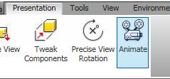
- Describe and apply the CREATE VIEW, PRECISE VIEW ROTATION, TWEAK COMPONENT, and ANIMATE commands to create, tweak, and play the animation of an exploded assembly.
Presentation Files
After the model is assembled in the assembly file, a presentation file can be created using it. A presentation file is a file in which a view of an assembly is exploded and can be animated. It can also be rotated so that is can be viewed from different angles. A presentation file is created using the NEW command and selecting a presentation template. A presentation file has the extension .ipn. IPN is an acronym for Inventor PreseNtation.
Exploded Views
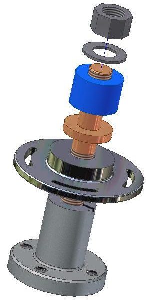
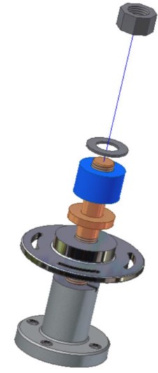
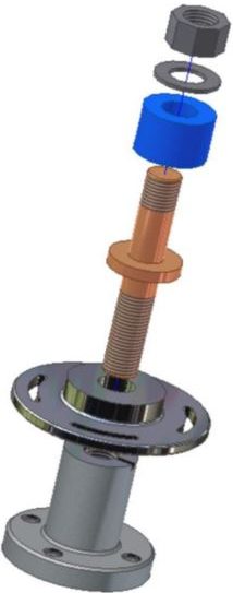
An exploded view shows the assembly as if it were dismantled and the components of the assembly shown in the order and orientation that they fit together to create the assembly. Assemblies can be exploded automatically by Inventor, tweaked manually, or a combination of the two methods, complete with trails. A tweak is the distance that the part is moved from the grounded part while the trails are the lines in an exploded view that show the relationship of the component to the assembly. Combined, they indicate the direction and distance that a component was moved to create the view. Exploded assembly drawings are used in design presentations, catalogues, and assembly instruction. Figure 23-1 shows an exploded and rotated view of an assembly.
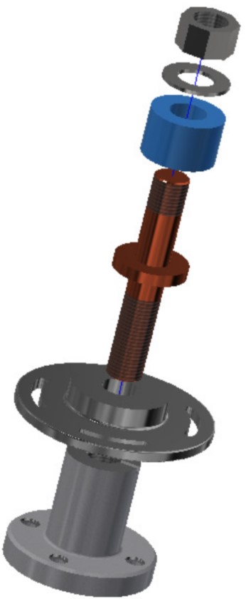
An Exploded and Rotated
Presentation Model
Animations
An animation is a series of images of an exploded assembly showing each components tweak at a set interval speed making a small motion picture of an assembly or a disassembly.
Tweaking
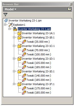
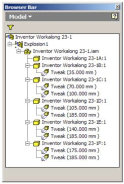
Tweaking is the process of moving the components from the grounded component. The tweak is the distance measured from the grounded unit. In the automated explosion method, the tweak distance is same for each part. If the tweak distance is set to 35, that means the first part is 35 mm from its location and the second part is 70 mm etc. This can be seen if the children in the Browser bar are expanded as shown in Figure 23-2. To tweak components manually, use the TWEAK COMPONENT command.
Tweaking
Animating the Exploded Assembly
After the exploded assembly is tweaked, it can animated to show the assembly and the disassembly of the model. An animation is simply a series of frames or pictures of the assembly displayed one frame at a time. The amount of time between frames is called the interval. The larger the interval, the slower the animation and the shorter the interval, the faster the animation. The number of repetitions can also be set.
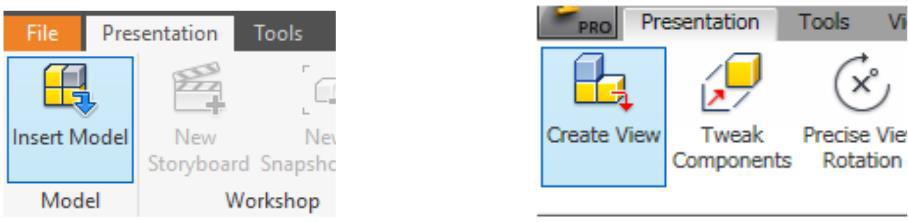
Inventor Command: CREATE VIEW or INSERT MODEL
The CREATE VIEW or INSERT MODEL commands are used to insert the model of the assembly file.
Shortcut: none
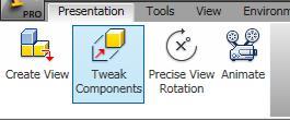
Inventor Command: TWEAK COMPONENTS
The TWEAK COMPONENTS command is used to move a component farther or closer from the grounded component to create or edit an exploded view of the assembly. It can also be used to rotate the components.
Shortcut: T
Inventor Command: ANIMATE
The ANIMATE command is used to set the parameters and play an animation of an assembly or disassembly of a assembled model.
Shortcut: none
WORK ALONG: Creating an Assembly and Presentation File
Step 1
Check the default project and if necessary, set it to Inventor Course.
Step 2
Use the following instructions to complete all parts in this workalong. Create the following parts and ensure that you do the following:
A Each part must be saved in its own .ipt file.
B Project the Center Point onto the Base sketch plane and note the location of X0Y0Z0.
C Draw the necessary sketches and extrude or revolve them to produce the solid model. Apply all of the necessary geometrical and dimensional constraints to fully constrain it.
D Apply the colour and material shown.
Step 3
Create the part file as follows:
Part: Base
Part Name: Inventor Workalong 23-1A Template: Metric-Modules Part (mm).ipt Color: Aluminum Cast Material: Aluminum 6061 (Figure Step 3A and 3B)
Template: Metric-Modules Part (mm).ipt
Color: Aluminum
Cast Material: Aluminum 6061 (Figure Step 3A and 3B)
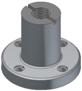
Solid Model – Home View
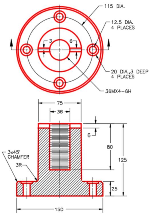
Dimensioned Multiview Drawing [Click to see image full size]
Step 4
Change the colour of the machined faces to: Mirror.
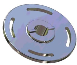
Part: Slotted Wheel
Part Name: Inventor Workalong 23-1B
Template: Metric-Modules Part (mm).ipt
Color: Mirror
Material: Chrome – Polished Blue (Figure Step 4A, 4B, and 4C)
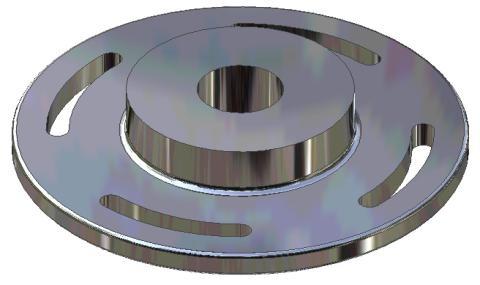
Solid Model – Home View
Solid Model – Orbited View
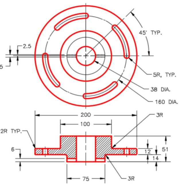
Dimensioned Multiview Drawing
Part: Connecting Shaft
Part Name: Inventor Workalong 23-1C
Template: Metric-Modules Part (mm).ipt
Color: Copper – Polished
Material: Copper (Figure Step 4D and 4E)
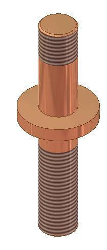
Solid Model –
Home View
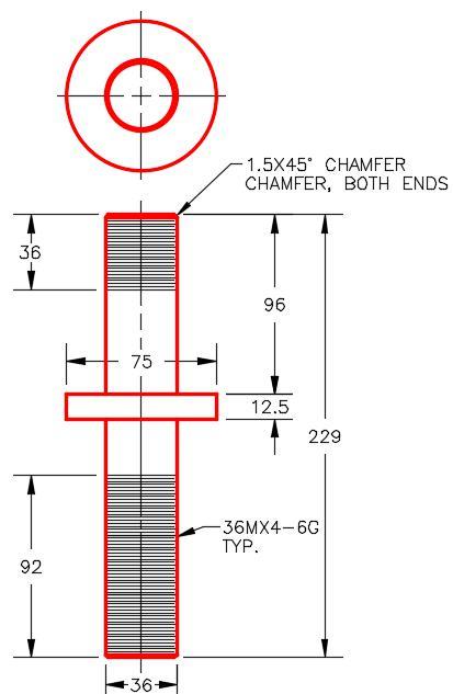
Dimensioned Multiview Drawing
Part: Spacer
Part Name: Inventor Workalong 23-1D
Template: Metric-Modules Part (mm).ipt
Color: Blue – Wall Paint – Glossy
Material: ABS Plastic (Figure Step 4F and 4G)
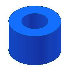
Solid Model –
Home View
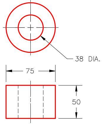
Dimensioned
Multiview Drawing
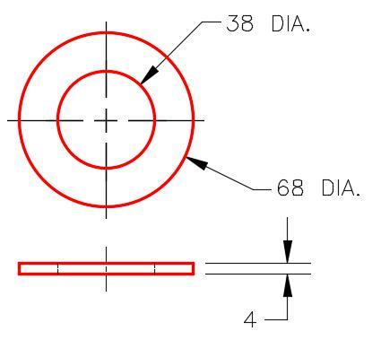
Part: Washer
Part Name: Inventor Workalong 23-1E
Template: Metric-Modules Part (mm).ipt
Color: Steel – Polished
Material: Steel (Figure Step 4H and 4J)
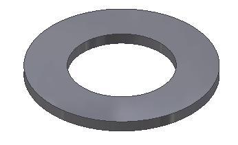
Solid Model –
Home View
Part: Nut
Part Name: Inventor Workalong 23-1F
Template: Metric-Modules Part (mm).ipt
Color: Steel – Polished
Material: Steel (Figure Step 4K and 4L)
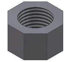
Solid Model –
Home View
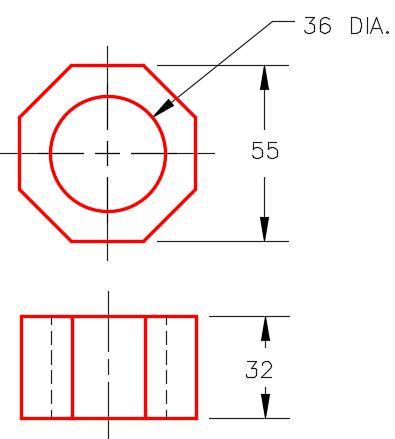
Dimensioned
Multiview Drawing
Step 5
Assemble all of the parts that you just created as shown in the figures.
Assembly: Slotted Connector
Assembly Name: Inventor Workalong 23-1.iam
Template: Metric-Modules Assembly (mm).iam (Figure Step 5A and 5B)
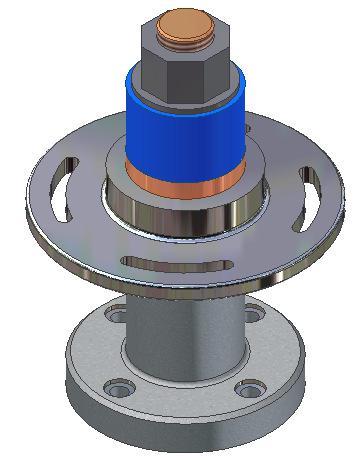
Assembly – Home View
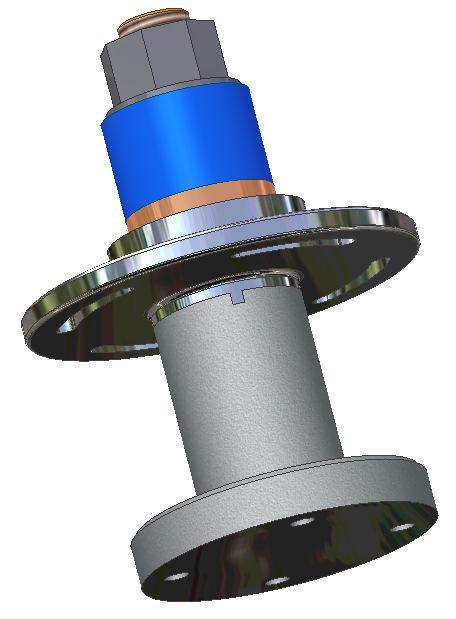
Assembly – Orbited View
Step 6
Enter the NEW command and enable the Metric tab. Select the template file: Modules Presentation (mm).ipn (Figure Step 6)

Step 6
Step 7
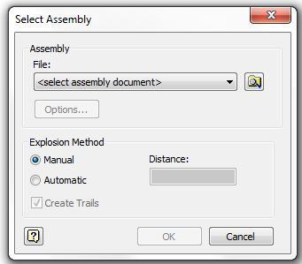
Enter the CREATE VIEW command. It will open the Select Assembly dialogue box. (Figure Step 7)
Step 8
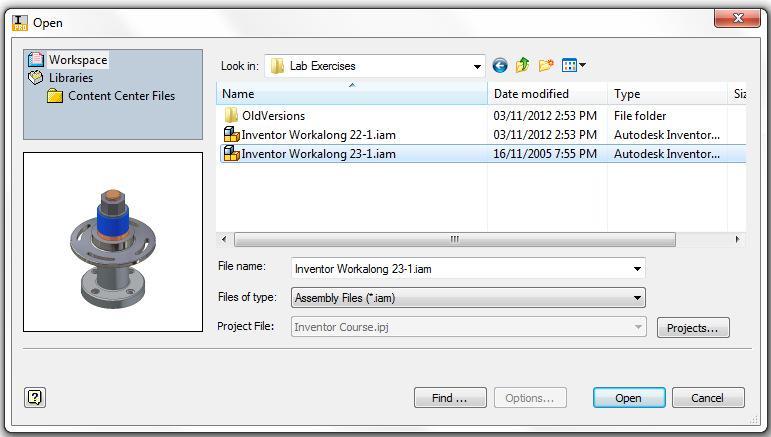
Click the Search Folder icon at the end of the file name. It will open the Open dialogue box. In the Lab Exercises folder, select the file: Inventor Workalong 23-1.iam and click Open. (Figure Step 8)
Step 9
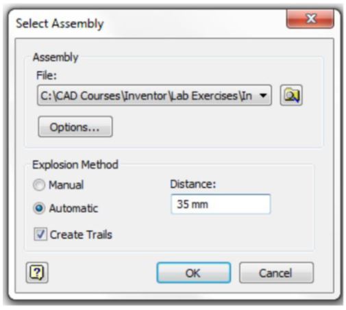
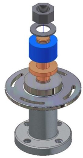
In the Select Assembly dialogue box enable Automatic and Create Trails in the Explosion Method area. Enter the Distance of 35 mm. Click OK. The exploded assembly should appear as shown in the figure. (Figure Step 9A and 9B)
Step 10
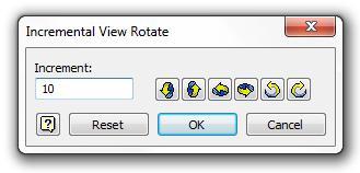
Enter the PRECISE VIEW ROTATION command. In the Incremental View Rotate dialogue box, set the Increment to 10. (Figure Step 10)
Step 11
Click the Right Rotate icon twice. This will rotate the model 20 degrees to the right. Click the Up Rotate icon once. This will rotate the model 10 degrees upwards. (Figure Step 11)
Step 12
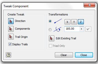
Enter the TWEAK COMPONENTS command. It will open the Tweak Component dialogue box. Set it as shown in the figure. (Figure Step 12)
Step 13
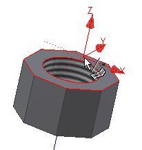
Ensuring that Direction is enabled, zoom in and move the cursor on the top of the nut. When the direction icon is displayed as shown in the figure, click the left mouse button. (Figure Step 13A and 13B)
Step 14
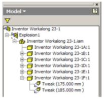
Look at the Browser bar for the tweak you just created. It will show two tweaks for part:
Inventor Workalong 23-1F:1, which is the nut. The 175.000 mm tweak was created in the automatic explosion in Step 9 and the 185.000 mm from the manual tweak you just completed. (Figure Step 14)
Step 15
Click the Clear button to clear the current settings. Using the Browser bar in Figure Step 15A, manually tweak the assembly to match the figure shown in Figure Step 15B. (Figure Step 15A and 15B)
Step 16
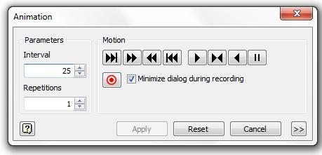
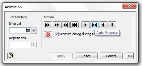
Enter the ANIMATE command. It will open the Animation dialogue box. Set the Interval to 25 and the Repetitions to 1. (Figure Step 16)
Step 17
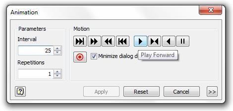
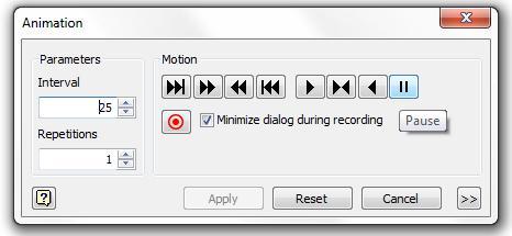
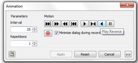
Study Figure Step 17A, 17B, 17C, and 17D. Play the animation of the assembly that you created in this workalong. Try the different options allowed in the Motion box. (Figure Step 17A, 17B, 17C, and 17D)
Step 18
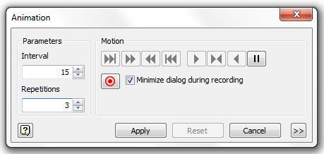
Set the Interval to 15 and the Repetitions to 3. Play the animation using these parameters both forward and in reverse. (Figure Step 18)
Step 19
Save and close the file.
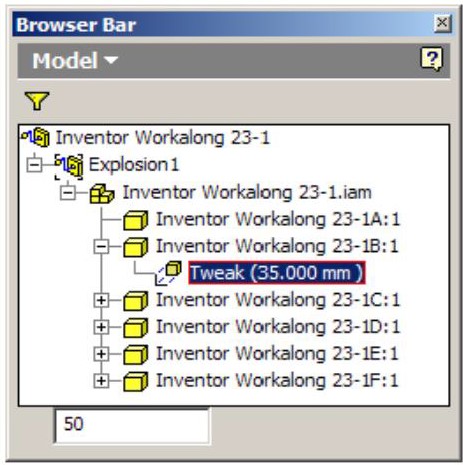
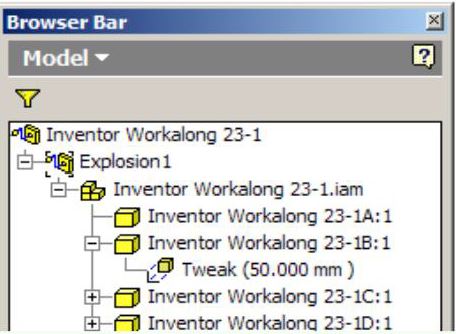
USER TIP: The tweaked distance can be edited in the Browser bar. Locate the tweak you want to change and select it. Once selected, it will highlight and at the bottom of the browser bar you can change the distance as shown in figure below left. The revised tweak will display as shown in the figure below right.
Key Principles
Key Principles in Module 23
- A presentation file is a file in which a view of an assembly is exploded and can be animated. It can be rotated so that is can be viewed from different angles.
- An exploded view shows the assembly as if it were dismantled and the components of the assembly shown in the order and orientation they fit together to create the assembly.
- A tweak is the distance that the part is moved from the grounded part while the trails are the lines in an exploded view that show the relationship of the component to the assembly.
- After the exploded assembly is tweaked, it can animated to show the assembly and the disassembly of the model. An animation is simply a series of frames or pictures of the assembly displayed one frame at a time. The amount of time between frames is called the interval.