5.3: Module 24 2D Drawings – Part 1
- Page ID
- 19889

\( \newcommand{\vecs}[1]{\overset { \scriptstyle \rightharpoonup} {\mathbf{#1}} } \)
\( \newcommand{\vecd}[1]{\overset{-\!-\!\rightharpoonup}{\vphantom{a}\smash {#1}}} \)
\( \newcommand{\id}{\mathrm{id}}\) \( \newcommand{\Span}{\mathrm{span}}\)
( \newcommand{\kernel}{\mathrm{null}\,}\) \( \newcommand{\range}{\mathrm{range}\,}\)
\( \newcommand{\RealPart}{\mathrm{Re}}\) \( \newcommand{\ImaginaryPart}{\mathrm{Im}}\)
\( \newcommand{\Argument}{\mathrm{Arg}}\) \( \newcommand{\norm}[1]{\| #1 \|}\)
\( \newcommand{\inner}[2]{\langle #1, #2 \rangle}\)
\( \newcommand{\Span}{\mathrm{span}}\)
\( \newcommand{\id}{\mathrm{id}}\)
\( \newcommand{\Span}{\mathrm{span}}\)
\( \newcommand{\kernel}{\mathrm{null}\,}\)
\( \newcommand{\range}{\mathrm{range}\,}\)
\( \newcommand{\RealPart}{\mathrm{Re}}\)
\( \newcommand{\ImaginaryPart}{\mathrm{Im}}\)
\( \newcommand{\Argument}{\mathrm{Arg}}\)
\( \newcommand{\norm}[1]{\| #1 \|}\)
\( \newcommand{\inner}[2]{\langle #1, #2 \rangle}\)
\( \newcommand{\Span}{\mathrm{span}}\) \( \newcommand{\AA}{\unicode[.8,0]{x212B}}\)
\( \newcommand{\vectorA}[1]{\vec{#1}} % arrow\)
\( \newcommand{\vectorAt}[1]{\vec{\text{#1}}} % arrow\)
\( \newcommand{\vectorB}[1]{\overset { \scriptstyle \rightharpoonup} {\mathbf{#1}} } \)
\( \newcommand{\vectorC}[1]{\textbf{#1}} \)
\( \newcommand{\vectorD}[1]{\overrightarrow{#1}} \)
\( \newcommand{\vectorDt}[1]{\overrightarrow{\text{#1}}} \)
\( \newcommand{\vectE}[1]{\overset{-\!-\!\rightharpoonup}{\vphantom{a}\smash{\mathbf {#1}}}} \)
\( \newcommand{\vecs}[1]{\overset { \scriptstyle \rightharpoonup} {\mathbf{#1}} } \)
\( \newcommand{\vecd}[1]{\overset{-\!-\!\rightharpoonup}{\vphantom{a}\smash {#1}}} \)
\(\newcommand{\avec}{\mathbf a}\) \(\newcommand{\bvec}{\mathbf b}\) \(\newcommand{\cvec}{\mathbf c}\) \(\newcommand{\dvec}{\mathbf d}\) \(\newcommand{\dtil}{\widetilde{\mathbf d}}\) \(\newcommand{\evec}{\mathbf e}\) \(\newcommand{\fvec}{\mathbf f}\) \(\newcommand{\nvec}{\mathbf n}\) \(\newcommand{\pvec}{\mathbf p}\) \(\newcommand{\qvec}{\mathbf q}\) \(\newcommand{\svec}{\mathbf s}\) \(\newcommand{\tvec}{\mathbf t}\) \(\newcommand{\uvec}{\mathbf u}\) \(\newcommand{\vvec}{\mathbf v}\) \(\newcommand{\wvec}{\mathbf w}\) \(\newcommand{\xvec}{\mathbf x}\) \(\newcommand{\yvec}{\mathbf y}\) \(\newcommand{\zvec}{\mathbf z}\) \(\newcommand{\rvec}{\mathbf r}\) \(\newcommand{\mvec}{\mathbf m}\) \(\newcommand{\zerovec}{\mathbf 0}\) \(\newcommand{\onevec}{\mathbf 1}\) \(\newcommand{\real}{\mathbb R}\) \(\newcommand{\twovec}[2]{\left[\begin{array}{r}#1 \\ #2 \end{array}\right]}\) \(\newcommand{\ctwovec}[2]{\left[\begin{array}{c}#1 \\ #2 \end{array}\right]}\) \(\newcommand{\threevec}[3]{\left[\begin{array}{r}#1 \\ #2 \\ #3 \end{array}\right]}\) \(\newcommand{\cthreevec}[3]{\left[\begin{array}{c}#1 \\ #2 \\ #3 \end{array}\right]}\) \(\newcommand{\fourvec}[4]{\left[\begin{array}{r}#1 \\ #2 \\ #3 \\ #4 \end{array}\right]}\) \(\newcommand{\cfourvec}[4]{\left[\begin{array}{c}#1 \\ #2 \\ #3 \\ #4 \end{array}\right]}\) \(\newcommand{\fivevec}[5]{\left[\begin{array}{r}#1 \\ #2 \\ #3 \\ #4 \\ #5 \\ \end{array}\right]}\) \(\newcommand{\cfivevec}[5]{\left[\begin{array}{c}#1 \\ #2 \\ #3 \\ #4 \\ #5 \\ \end{array}\right]}\) \(\newcommand{\mattwo}[4]{\left[\begin{array}{rr}#1 \amp #2 \\ #3 \amp #4 \\ \end{array}\right]}\) \(\newcommand{\laspan}[1]{\text{Span}\{#1\}}\) \(\newcommand{\bcal}{\cal B}\) \(\newcommand{\ccal}{\cal C}\) \(\newcommand{\scal}{\cal S}\) \(\newcommand{\wcal}{\cal W}\) \(\newcommand{\ecal}{\cal E}\) \(\newcommand{\coords}[2]{\left\{#1\right\}_{#2}}\) \(\newcommand{\gray}[1]{\color{gray}{#1}}\) \(\newcommand{\lgray}[1]{\color{lightgray}{#1}}\) \(\newcommand{\rank}{\operatorname{rank}}\) \(\newcommand{\row}{\text{Row}}\) \(\newcommand{\col}{\text{Col}}\) \(\renewcommand{\row}{\text{Row}}\) \(\newcommand{\nul}{\text{Nul}}\) \(\newcommand{\var}{\text{Var}}\) \(\newcommand{\corr}{\text{corr}}\) \(\newcommand{\len}[1]{\left|#1\right|}\) \(\newcommand{\bbar}{\overline{\bvec}}\) \(\newcommand{\bhat}{\widehat{\bvec}}\) \(\newcommand{\bperp}{\bvec^\perp}\) \(\newcommand{\xhat}{\widehat{\xvec}}\) \(\newcommand{\vhat}{\widehat{\vvec}}\) \(\newcommand{\uhat}{\widehat{\uvec}}\) \(\newcommand{\what}{\widehat{\wvec}}\) \(\newcommand{\Sighat}{\widehat{\Sigma}}\) \(\newcommand{\lt}{<}\) \(\newcommand{\gt}{>}\) \(\newcommand{\amp}{&}\) \(\definecolor{fillinmathshade}{gray}{0.9}\)24
Module 24 2D Drawings – Part 1
Wally Baumback
Learning Outcomes
When you have completed this module, you will be able to:
- Describe 2D drawing files, drawing sheets, and drawing sizes.
- Describe and apply the commands BASE VIEW, PROJECTED VIEW, SECTION VIEW, and NEW SHEET to create multiview and isometric views of a solid model on a drawing sheet.
Drawing Files
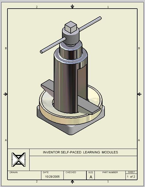
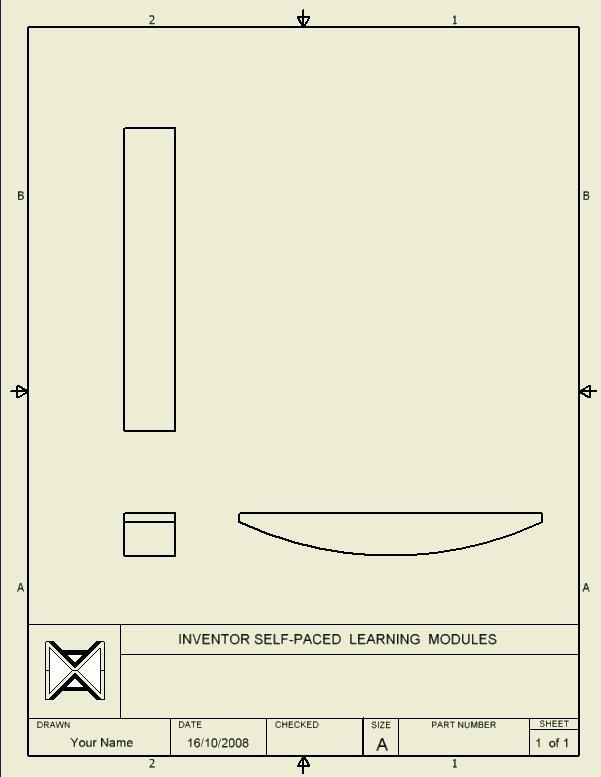
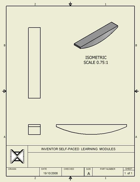
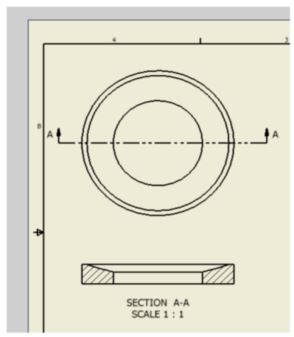
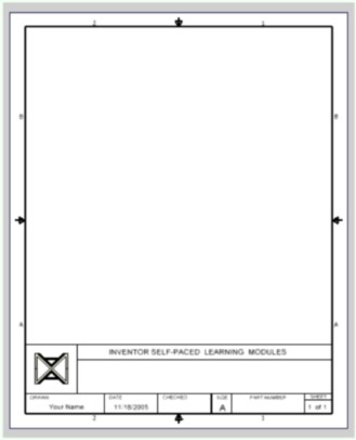
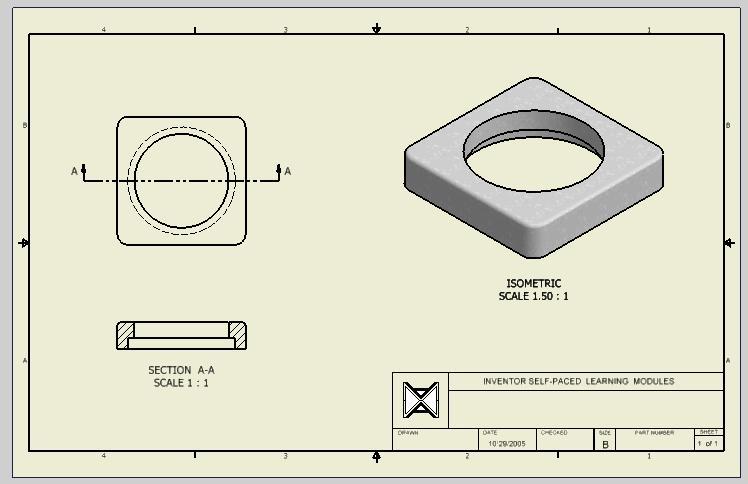
A drawing file contains one or more drawing sheets on which 2 dimensional and/or 3 dimensional scaled views of the solid models contained in part, assembly, or presentation files. The views can be created complete with hidden lines or shading. Annotation can be automatically or manually added to the views as required. A typical drawing sheet with an orthographic, section, and isometric view of a model is shown in Figure 24-1. Dimensioning, inserting text, and filling in the titleblock are taught in Module 25. When the drawing is complete, it can be printed or plotted on paper. A drawing file has the file extension .idw. IDW is an acronym for Inventor Drawing.
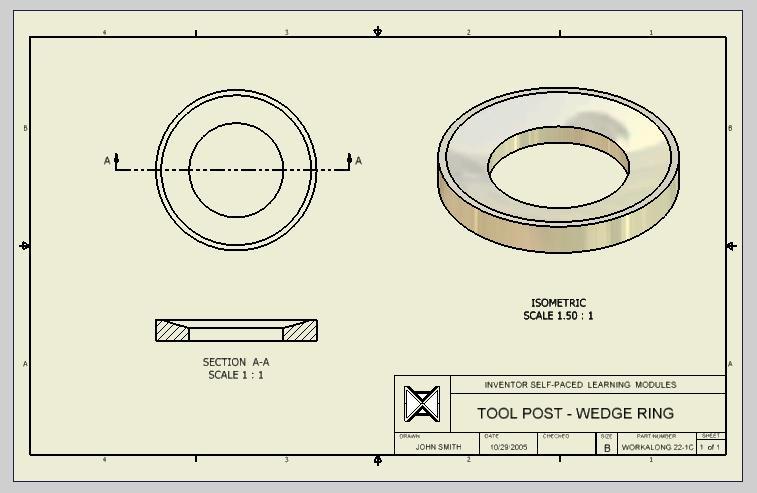
A Typical Drawing Sheet in a Drawing File [Click to see image full size]
Model Views
Amodel view is a scaled view orientated at an angle and direction that the solid model or assembly is being viewed and displayed on the drawing sheet. There is no limit to the number of views or the number of solid models from part, assembly, or presentation files that can be placed on a drawing sheet. Views can also be automatically annotated or labeled. There are eight predefined views that you can select from when creating the view. The predefined views are the; base, projection, auxiliary, section, detail, broken, breakout, and overlay.
The Base
A Base view is the first view created on the drawing sheet. It controls the scale, orientation, and location of the views projected from it. The orthographic and/or isometric views in the drawing are created from the Base view. For example, if a multiview drawing was being created from a solid model, the Front view is created first as a Base view. The Front view would control the scale and location of the projected Top and Right Side views. See Figure 24-2. To change the scale of all views, only the scale of the Front (Base) view would have to be changed and the Top and Right Side views would automatically change scale to match. If the Front view was moved, the Top and Right Side views would move accordingly to keep their multiview position.
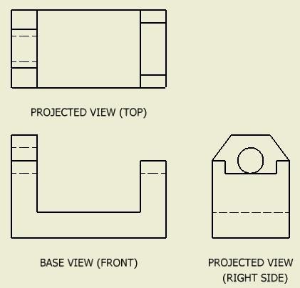
Multiview Drawing
Projected Views
A projected view is a view projected from a Base view. The scale of a projected view cannot be set since the Base view that you projected it from controls its scale. The Base view also controls the orientation and location of the projected views.
Drawing Sheets
A drawing sheet represents a blank piece of paper complete with titleblock and border. The size of drawing sheet can be set by the user. The sheet size can be a custom size set by you or one of the ANSI or ISO drawing sheet standards listed in the table shown in Figure 24-3.
There is no maximum number of drawing sheets that can be created for each drawing file but there must be at least one sheet. Sheets can be created or deleted but Inventor will NOT allow all of them to be deleted since one sheet must exist at all times.
The drawing sheet can be assigned a drawing border and a titleblock which can be created or edited by you. Custom drawing template files containing borders and titleblocks are supplied with the Inventor book.
MUST KNOW: There is no maximum number of drawing sheets that can be created for each drawing file but there must be at least one sheet. One sheet must exist in each drawing file at all times.ANSI and ISO Standard Drawing Sheet Sizes
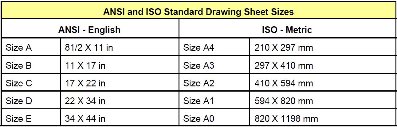
Standard ANSI and ISO Drawing Sheet Sizes
View Style
Aview style can be displayed in one of three different styles. The three styles are hidden line, hidden line removed, and shaded as shown in Figure 24-4. The style of a view can be changed as required after the view has been placed.
View Scale
The scale of the view is a factor of the number that it is set to. For example, if the scale is set to 1 then the factor of 1 X 1 = 1, full scale or 1:1. If the scale is set to 2 then 2 X 1 = 2 or a scale of 2:1 which is twice the size of the original model. On the other hand, if the scale factor is set to 0.5 then 0.5 X 1 = 0.5 or the scale of 1:2 which would display the view one-half the size of the original model.
View Styles
Inventor Command: BASE VIEW
The BASE VIEW command is used to create a Base view of the solid model contained in a part, assembly, or presentation file on the drawing sheet. The scale, style, labeling, and orientation of the view can be set when the view is created.
Shortcut: none
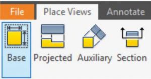
Inventor Command: PROJECTED VIEW
The PROJECTED VIEW command is used to create a projected view from a Base view. The style, labeling, and direction from the Base view can be set by you when the view is created.
Shortcut: none
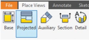
Inventor Command: SECTION VIEW
The SECTION VIEW command is used to create a Section view from an existing view. The location, style, labeling, and direction from the selected view can be set by you when the view is created.
Shortcut: none
ISO is an acronym for International Organization for Standardization. ISO has set the drawing standards that are widely adapted and followed by most companies working in Metric measurements. To read more about ISO see: http://www.iso.org/iso/en/ISOOnline.frontpage
WORK ALONG: Creating 2D Drawings
Step 1
Check the default project and if necessary, set it to: Inventor Course.
Step 2
Enter the NEW command to start a new drawing file. Enable the English tab and select the template: Modules Drawing ANSI (in).idw. (Figure Step 2)
Step 2
Step 3
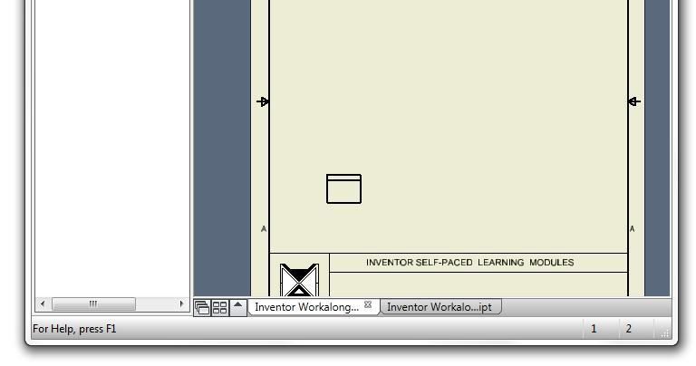
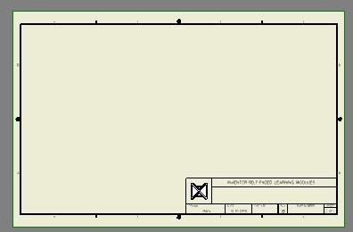
When the drawing file is opened, it will display an A size drawing complete with border and titleblock. Save the file with the name: Inventor Workalong 24-1. (Figure Step 3)
Step 4
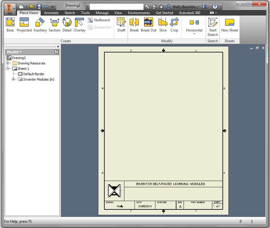
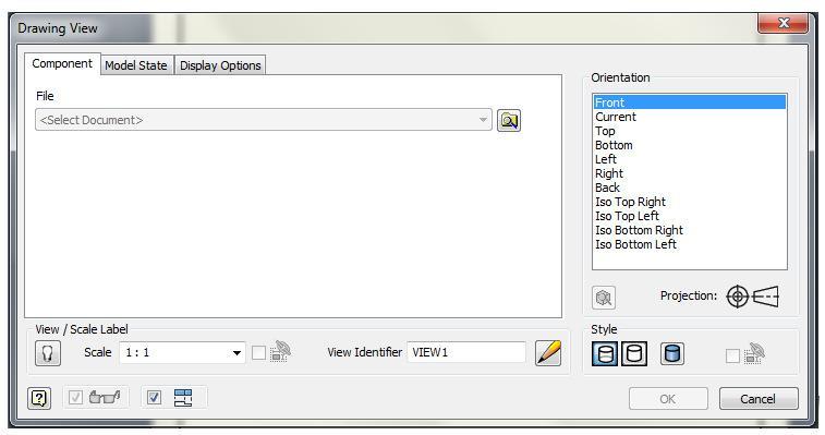
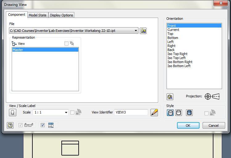
Enter the BASE VIEW command to create the Base view. It will open the Drawing View dialogue box. Set the Orientation (view) to Front and the Style to Hidden Line. Ensure that the dialogue box matches the figure. (Figure Step 4)
Step 5
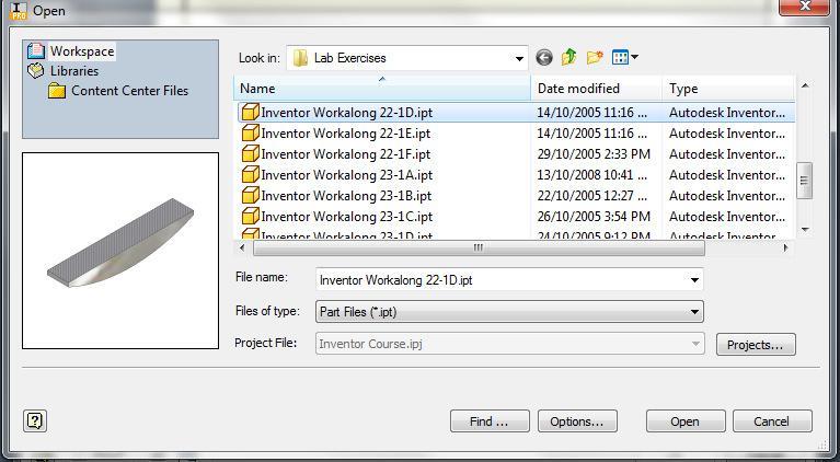
Click OK. In the Open dialogue box, select the part: Inventor Workalong 22-1D.ipt. (Figure Step 5)
Step 6
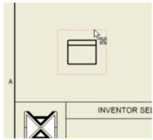
Select the location for the Front view. Don’t be too concerned where you locate it since it can be moved later. Try to locate it close to where it is shown in the figure. (Figure Step 6A and 6B)
Step 7
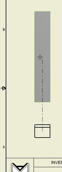
Enter the PROJECT VIEW command and select the Base view as the view to project from. (Figure Step 7)
Step 8
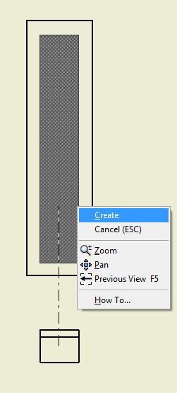
Move the cursor up to locate the Top view. Click the mouse at the desired location. Right click the mouse. In the Right-click menu, select Create. (Figure Step 8A and 8B)
Step 9
Using what you just learned, use the PROJECT VIEW command to create the Right Side view. (Figure Step 9)
Step 10
Your drawing should now contain the Top, Front and Right Side views of the part. (Figure Step 10)
Step 11
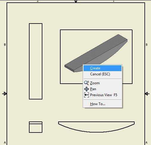
Enter the PROJECT VIEW command. Select the Base view (Front view) and project an Isometric view from it. (Figure Step 11)
Step 12
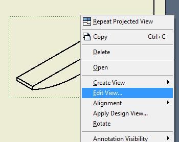
Right click the Isometric view. In the Right-click menu, click Edit View. (Figure Step 12)
Step 13
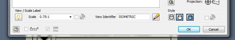
In the Edit View dialogue box enable the display View/Scale label (turn the light bulb on). Set the Scale to 0.75:1, View Identifier to ISOMETRIC and the Style to Shaded. (Figure Step 13A and 13B)
Step 14
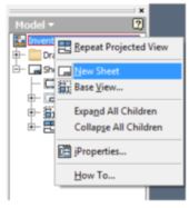
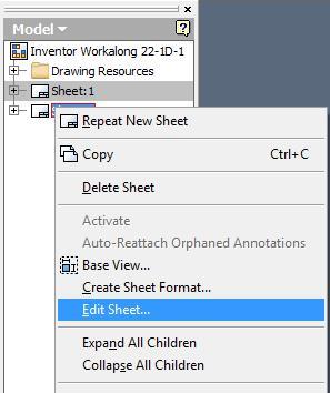
Right click the file name in the Browser bar. In the Right-click menu, click New Sheet. An A size drawing sheet will display in the Graphic window. The new sheet will be labeled Sheet:2 and will display in the Browser bar. (Figure Step 14)
Step 15
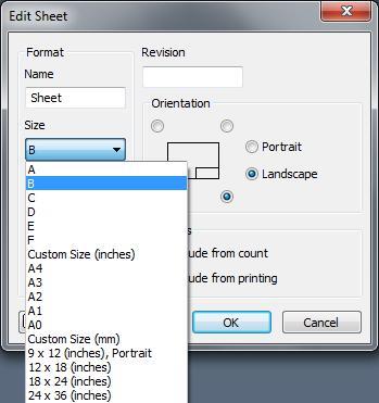
Right-click Sheet:2. In the Right-click menu, click Edit Sheet. In the Edit Sheet dialogue box, pull down the Size list and select B to change Sheet 2 to a B size. Ensure that Landscape is enable. (Figure 15A, 15B, and 15C)
Step 16
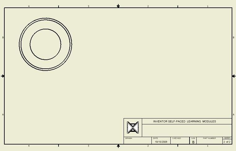
Using what you just learned, create a Base view of Top view of part: Inventor Workalong 22-1C.ipt that you created in Module 22. (Figure Step 16)
Step 17
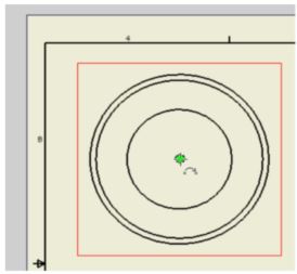
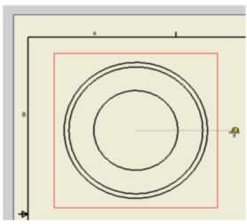
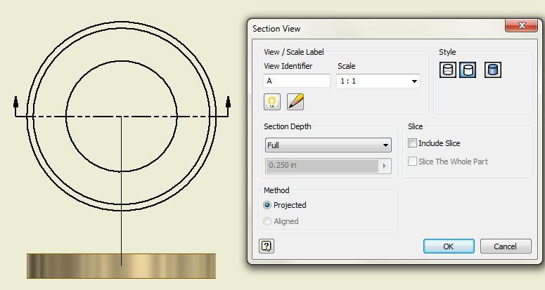
Enter the SECTION VIEW command. Move the cursor to the centre of the circle on the Top view until it displays the green snap circle. You may have to move the cursor touching the circle circumference and then move back to the centre. Do NOT select the green snap circle, wait until it displays. Move the cursor to the right and you will see a dashed line indicating an implied line which is orthographic or horizontal, in this case. move outside the view. The yellow grid snap circle will display. Select a location when the grid snap is displayed. (Figure Step 17A and 17B)
Step 18
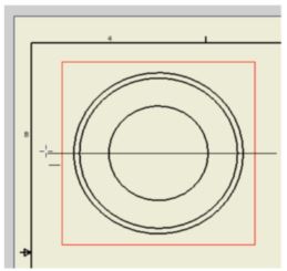
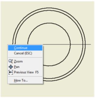
Move the cursor across to the other side of the view and when the geometry constraint (horizontal) displays, select a location about the same distance from the view as you did for the other side of the view. Right-click the mouse. In the Right-click menu, select Continue. (Figure Step 18A and 18B)
Step 19
Move the cursor down and the section view will display. The Section View dialogue box will open. Set the dialogue box as shown in the figure. (Figure Step 19A and 19B)
Step 20
Using the BASE VIEW command, create an Isometric view and set the scale to 1.25:1. (Figure Step 20)
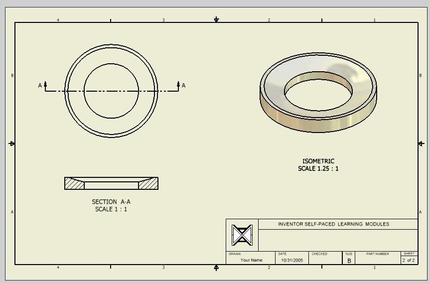
Step 21
Save and close the drawing file.
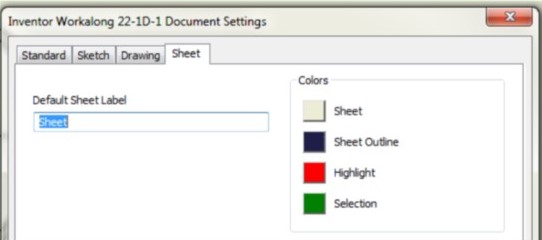
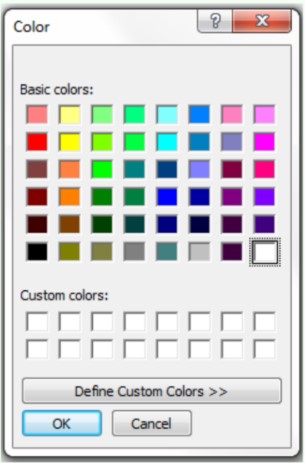
USER TIP: The default labels and colors can be configured for each drawing file. Originally, these setting came from the template file that you used to start the drawing file. Any changes that you make will only affect the current drawing file. Enter the DOCUMENT SETTINGS command. See figure right. To change the default labels of the sheets, simply edit the value as shown in the figure below. To change the background colour of the Sheet, the Sheet Outline, Highlight or Selection, select the one you want from the Color dialogue box. In this example, the colour of the sheet was change to white.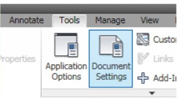
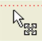
 USER TIP: To move a view on the drawing sheet, move the cursor onto the view’s border. When you are on the border, it will highlight as shown in Step 1. If the view is a base view or a projected view that has a view dependent on it, the Graphic cursor will display as shown on the left. If the view is a Base view or a projected view that does NOT have view dependent on it, the cursor will display as shown on the right. To move a view, simply press and hold down the left mouse button and drag it to desired location as shown in Step 2.
Key Principles
Key Principles in Module 24
- A drawing file contains one or more 2 dimensional drawing sheets on which a 2D and/or 3D scaled views of solid models contained in part, assembly, and presentation files. A drawing file has the file extension .idw. IDW is an acronym for Inventor Drawing.
- A Base view is the first view created by the user. It controls the scale, orientation, and location of the orthographic views projected from it.
- A projected view is a view projected from a Base view. The scale of a projected view cannot be set since the Base view that you projected it from controls its scale. The Base view also controls the orientation and location of the projected views.
- A drawing sheet represents a blank piece of paper complete with titleblock and border. The size of drawing sheet can be set by the user. The sheet size can be a custom size set by the user or one of the ANSI or ISO drawing sheet standards.
- There is no maximum number of drawing sheets that can be created for each drawing file but there must be at least one sheet. One sheet must exist in each drawing file at all times.
- A view style can be displayed in one of three different styles. The three styles are hidden line, hidden line removed, and shaded. The style of a view can be changed as required after the view has been placed.
- The scale of the view is a factor of the number that it is set to.
Move 
Project 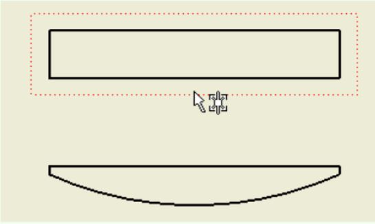
Step 1 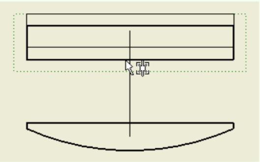
Step 2
Lab Exercise 24-1
Time allowed: 2 hours.
| Part Name | Project | Units | Template | Color | Material |
| See Below | Inventor Course | Inches | See Below | N/A | N/A |
Step 1
Create the following drawings and ensure the following:
A There is a separate file for each drawing sheet.
B Create the same views as shown.
C If the scale is not indicated, set it to full scale or 1:1.
D Each drawing file has only one drawing sheet.
E Save the drawing files with the Drawing Name shown for each part.
Part: Base
Drawing Size: B
Drawing Name: Inventor Lab 24-1A.idw Part Name: Inventor Workalong 22-1A.ipt
Template: English-Modules Drawing ANSI (in).idw (Figure Step 1A)
Part: Post
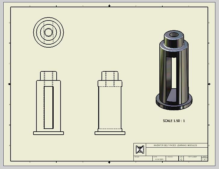
Drawing Size: C
Drawing Name: Inventor Lab 24-1B.idw
Part Name: Inventor Workalong 22-1B.ipt
Template: English-Modules Drawing ANSI (in).idw (Figure Step 1B)
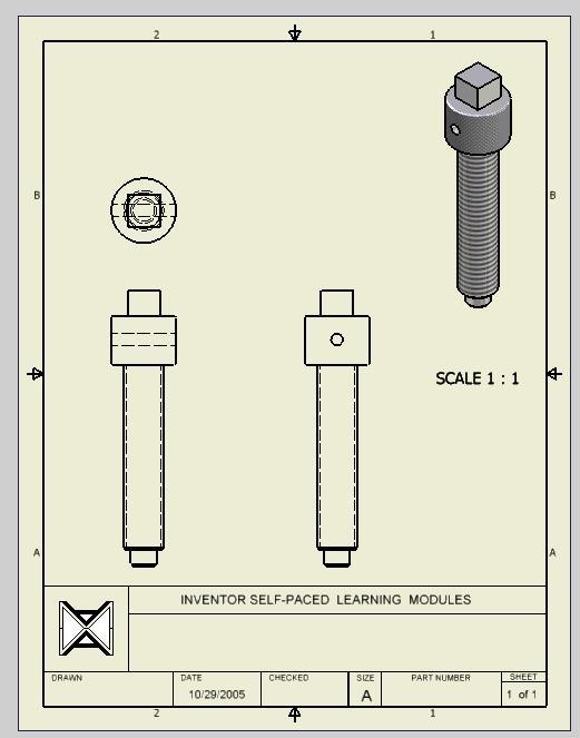
Part: Screw
Drawing Size: A
Drawing Name: Inventor Lab 24-1C.idw
Part Name: Inventor Workalong 22-1E.ipt
Template: English-Modules D
rawing ANSI (in).idw (Figure Step 1C)
Assembly: Tool Holder
Drawing Size: A
Drawing Name: Inventor Lab 24-1.idw
Part Name: Inventor Workalong 22-1.iam
Template: English-Modules Drawing ANSI (in).idw (Figure Step 1D)