5.5: Module 26 Competency Test No. 5 Open Book
- Page ID
- 19891
\( \newcommand{\vecs}[1]{\overset { \scriptstyle \rightharpoonup} {\mathbf{#1}} } \)
\( \newcommand{\vecd}[1]{\overset{-\!-\!\rightharpoonup}{\vphantom{a}\smash {#1}}} \)
\( \newcommand{\id}{\mathrm{id}}\) \( \newcommand{\Span}{\mathrm{span}}\)
( \newcommand{\kernel}{\mathrm{null}\,}\) \( \newcommand{\range}{\mathrm{range}\,}\)
\( \newcommand{\RealPart}{\mathrm{Re}}\) \( \newcommand{\ImaginaryPart}{\mathrm{Im}}\)
\( \newcommand{\Argument}{\mathrm{Arg}}\) \( \newcommand{\norm}[1]{\| #1 \|}\)
\( \newcommand{\inner}[2]{\langle #1, #2 \rangle}\)
\( \newcommand{\Span}{\mathrm{span}}\)
\( \newcommand{\id}{\mathrm{id}}\)
\( \newcommand{\Span}{\mathrm{span}}\)
\( \newcommand{\kernel}{\mathrm{null}\,}\)
\( \newcommand{\range}{\mathrm{range}\,}\)
\( \newcommand{\RealPart}{\mathrm{Re}}\)
\( \newcommand{\ImaginaryPart}{\mathrm{Im}}\)
\( \newcommand{\Argument}{\mathrm{Arg}}\)
\( \newcommand{\norm}[1]{\| #1 \|}\)
\( \newcommand{\inner}[2]{\langle #1, #2 \rangle}\)
\( \newcommand{\Span}{\mathrm{span}}\) \( \newcommand{\AA}{\unicode[.8,0]{x212B}}\)
\( \newcommand{\vectorA}[1]{\vec{#1}} % arrow\)
\( \newcommand{\vectorAt}[1]{\vec{\text{#1}}} % arrow\)
\( \newcommand{\vectorB}[1]{\overset { \scriptstyle \rightharpoonup} {\mathbf{#1}} } \)
\( \newcommand{\vectorC}[1]{\textbf{#1}} \)
\( \newcommand{\vectorD}[1]{\overrightarrow{#1}} \)
\( \newcommand{\vectorDt}[1]{\overrightarrow{\text{#1}}} \)
\( \newcommand{\vectE}[1]{\overset{-\!-\!\rightharpoonup}{\vphantom{a}\smash{\mathbf {#1}}}} \)
\( \newcommand{\vecs}[1]{\overset { \scriptstyle \rightharpoonup} {\mathbf{#1}} } \)
\( \newcommand{\vecd}[1]{\overset{-\!-\!\rightharpoonup}{\vphantom{a}\smash {#1}}} \)
\(\newcommand{\avec}{\mathbf a}\) \(\newcommand{\bvec}{\mathbf b}\) \(\newcommand{\cvec}{\mathbf c}\) \(\newcommand{\dvec}{\mathbf d}\) \(\newcommand{\dtil}{\widetilde{\mathbf d}}\) \(\newcommand{\evec}{\mathbf e}\) \(\newcommand{\fvec}{\mathbf f}\) \(\newcommand{\nvec}{\mathbf n}\) \(\newcommand{\pvec}{\mathbf p}\) \(\newcommand{\qvec}{\mathbf q}\) \(\newcommand{\svec}{\mathbf s}\) \(\newcommand{\tvec}{\mathbf t}\) \(\newcommand{\uvec}{\mathbf u}\) \(\newcommand{\vvec}{\mathbf v}\) \(\newcommand{\wvec}{\mathbf w}\) \(\newcommand{\xvec}{\mathbf x}\) \(\newcommand{\yvec}{\mathbf y}\) \(\newcommand{\zvec}{\mathbf z}\) \(\newcommand{\rvec}{\mathbf r}\) \(\newcommand{\mvec}{\mathbf m}\) \(\newcommand{\zerovec}{\mathbf 0}\) \(\newcommand{\onevec}{\mathbf 1}\) \(\newcommand{\real}{\mathbb R}\) \(\newcommand{\twovec}[2]{\left[\begin{array}{r}#1 \\ #2 \end{array}\right]}\) \(\newcommand{\ctwovec}[2]{\left[\begin{array}{c}#1 \\ #2 \end{array}\right]}\) \(\newcommand{\threevec}[3]{\left[\begin{array}{r}#1 \\ #2 \\ #3 \end{array}\right]}\) \(\newcommand{\cthreevec}[3]{\left[\begin{array}{c}#1 \\ #2 \\ #3 \end{array}\right]}\) \(\newcommand{\fourvec}[4]{\left[\begin{array}{r}#1 \\ #2 \\ #3 \\ #4 \end{array}\right]}\) \(\newcommand{\cfourvec}[4]{\left[\begin{array}{c}#1 \\ #2 \\ #3 \\ #4 \end{array}\right]}\) \(\newcommand{\fivevec}[5]{\left[\begin{array}{r}#1 \\ #2 \\ #3 \\ #4 \\ #5 \\ \end{array}\right]}\) \(\newcommand{\cfivevec}[5]{\left[\begin{array}{c}#1 \\ #2 \\ #3 \\ #4 \\ #5 \\ \end{array}\right]}\) \(\newcommand{\mattwo}[4]{\left[\begin{array}{rr}#1 \amp #2 \\ #3 \amp #4 \\ \end{array}\right]}\) \(\newcommand{\laspan}[1]{\text{Span}\{#1\}}\) \(\newcommand{\bcal}{\cal B}\) \(\newcommand{\ccal}{\cal C}\) \(\newcommand{\scal}{\cal S}\) \(\newcommand{\wcal}{\cal W}\) \(\newcommand{\ecal}{\cal E}\) \(\newcommand{\coords}[2]{\left\{#1\right\}_{#2}}\) \(\newcommand{\gray}[1]{\color{gray}{#1}}\) \(\newcommand{\lgray}[1]{\color{lightgray}{#1}}\) \(\newcommand{\rank}{\operatorname{rank}}\) \(\newcommand{\row}{\text{Row}}\) \(\newcommand{\col}{\text{Col}}\) \(\renewcommand{\row}{\text{Row}}\) \(\newcommand{\nul}{\text{Nul}}\) \(\newcommand{\var}{\text{Var}}\) \(\newcommand{\corr}{\text{corr}}\) \(\newcommand{\len}[1]{\left|#1\right|}\) \(\newcommand{\bbar}{\overline{\bvec}}\) \(\newcommand{\bhat}{\widehat{\bvec}}\) \(\newcommand{\bperp}{\bvec^\perp}\) \(\newcommand{\xhat}{\widehat{\xvec}}\) \(\newcommand{\vhat}{\widehat{\vvec}}\) \(\newcommand{\uhat}{\widehat{\uvec}}\) \(\newcommand{\what}{\widehat{\wvec}}\) \(\newcommand{\Sighat}{\widehat{\Sigma}}\) \(\newcommand{\lt}{<}\) \(\newcommand{\gt}{>}\) \(\newcommand{\amp}{&}\) \(\definecolor{fillinmathshade}{gray}{0.9}\)26
Module 26 Competency Test No. 5 Open Book
Wally Baumback
Learning Outcomes
When you have completed this module, you will be able to:
- Within a six hour time limit, complete a written exam and the lab exercise.
The Inventor book was written with competency based modules. What that means is that you have not completed each module until you have mastered it. The Competency Test module contains multiple choice questions and a comprehensive lab exercise to test your mastery of the set of modules that you completed. There are no answers or keys supplied in a Competency Test module since it is meant to be checked by your instructor. If there are any parts of this module that you have trouble completing, you should go back and reread the module or modules containing the information that you are having trouble with. If necessary, redo as many lab exercises required until you fully understand the material.
If you are Completing this book:
- Without the aid of an instructor, complete the written test and the lab exercise.
- In a classroom with an instructor, the instructor will give instructions on what to do after you have completed this module.
Multiple Choice Questions
Select the BEST answer.
- What file extension does a presentation file have?
- .ipt
- .idw
- .iam
- .iaf
- .ipn
- What is the term used in an assembly file that refers to the part files linked to the assembly?
- link
- location
- indicator
- source
- reference
- What does the symbol “<<>>” signify in a dimension text?
- A reference dimension.
- The actual dimension number is a model or drawing dimension size.
- The text size.
- The dimension units of the model or drawing dimension.
- That there is no dimension.
- What is the name of first view you create on a drawing that controls the scale, orientation and location of the orthographical views projected from it?
- Section View
- Multiview
- Projected View
- Base view
- Orthographic view
- What command is used to get the model dimensions for a view?
- GET DIMENSION
- GENERAL DIMENSION
- RETRIEVE DIMENSION
- RECOVER DIMENSION
- OBTAIN DIMENSION
- What is the minimum and maximum number of drawing sheets that can exist in a single drawing file?
- Minimum – 1 Maximum – none
- Minimum – 1 Maximum – 10
- Minimum – 0 Maximum – none
- Minimum – 1 Maximum – 100
- Minimum – 0 Maximum – 10
- What file extension does a drawing file have?
- .ipt
- .idw
- .iam
- .iaf
- .ipn
- What is the method of the construction called when an assembly file is created from a series of part files that were previously created and saved in their own .IPT file?
- Part Assembly
- Bottom-up Assembly
- IPT Assembly
- Top-down Assembly
- Series Assembly
- What is the term used to describe the distances that the parts are moved from the grounded part in an explode assembly file?
- Distance
- Exploded
- Trails
- Animation
- Tweak
- What file extension does an assembly file have?
- .ipt
- .idw
- .iam
- .iaf
- .ipn
Lab Exercise 26-1
Time allowed: 6 hours.
| Part Name | Project | Units | Template | Color | Material |
| Inventor Lab 26-1 | Inventor Course | Inches | See Below | See Below | See Below |
Step 1
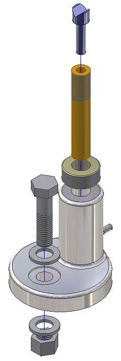
Create the following parts. Each part must have its own file and constructed as follows:
A Project the Center Point onto the Base plane.
B Select your own location for X0Y0Z0.
C Draw the necessary sketches and extrude or revolve them to produce the solid models. Apply all of the necessary geometrical and dimensional constraints to maintain the objects shape and size. All sketches must be fully constrained.
D Apply the colour and material shown.
E Ensure that you draw each part in the correct orientation so that they can be easily assembled together. The Home view for each part will help you. (Figure Step 1A, 1B, and 1C)
Solid Model – Home View
Solid Model – Orbited View
Dimensioned Multiview Drawing [Click to see image full size]
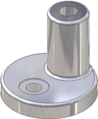
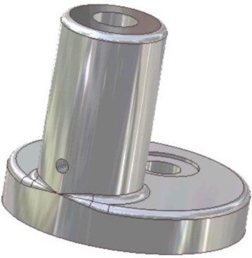
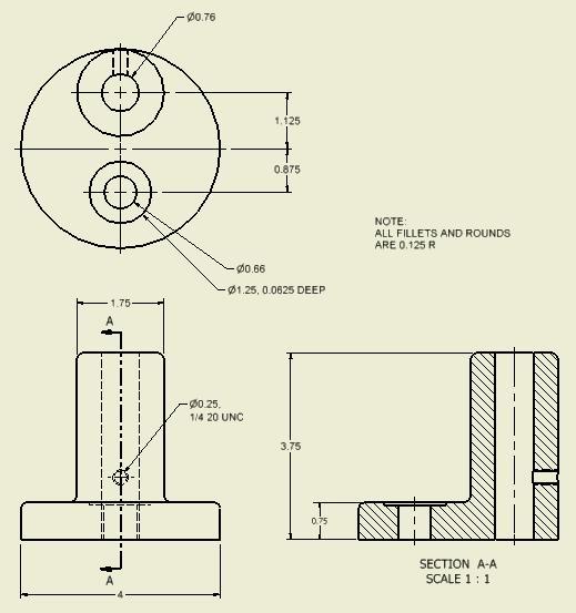
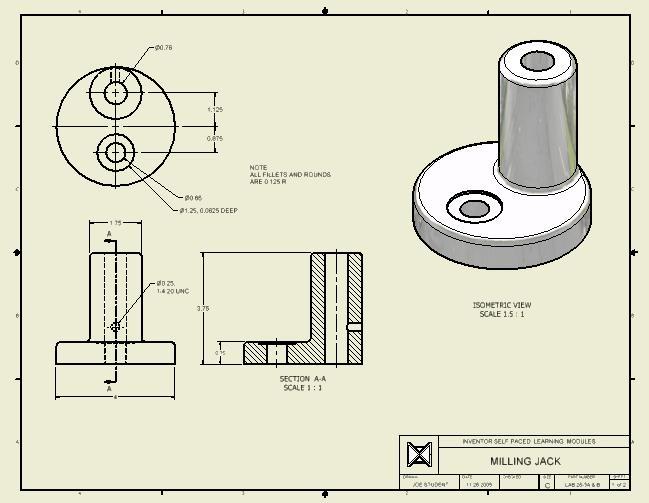
Part: Base
Part Name: Inventor Lab 26-1A
Template: English-Modules Part (in).ipt
Color: Steel – Polished
Material: Stainless Steel
Part: Adjustment Shaft
Part Name: Inventor Lab 26-1B
Template: English-Modules Part (in).ipt
Color: Brass – Satin
Material: Soft Yellow Brass (Figure Step 1D, 1E, and 1F)
Solid Model –
Home View
Solid Model –
Orbited View
Dimensioned Multiview Drawing
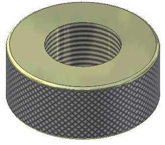
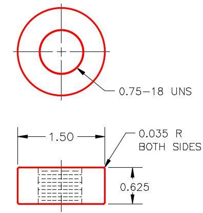
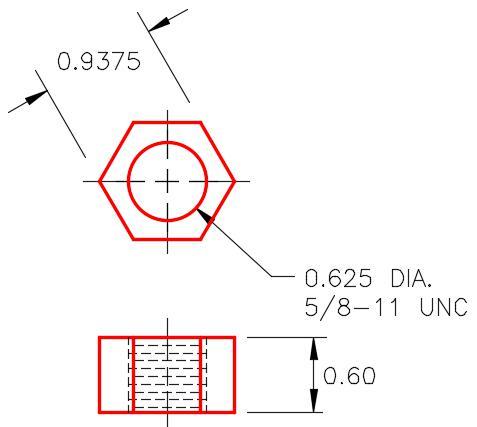
Part: Adjusting Nut
Part Name: Inventor Lab 26-1C
Template: English-Modules Part (in).ipt
Color: Nickel
Material: Non-Alloy Steel (Figure Step 1G and 1H)
Note: Knurl the outside of the nut.
Solid Model – Home View
Dimensioned Multiview Drawing
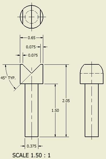
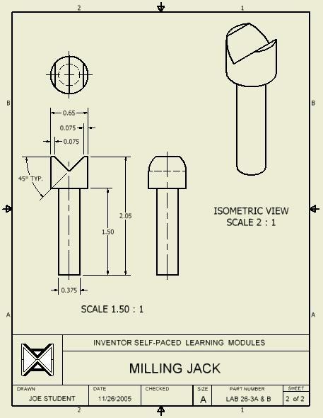
Part: V-Shaft
Part Name: Inventor Lab 26-1D
Template: English-Modules Part (in).ipt
Color: Chrome – Polished Blue
Material: Stainless Steel (Figure Step 1J and 1K)
Dimensioned Multiview Drawing
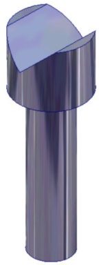
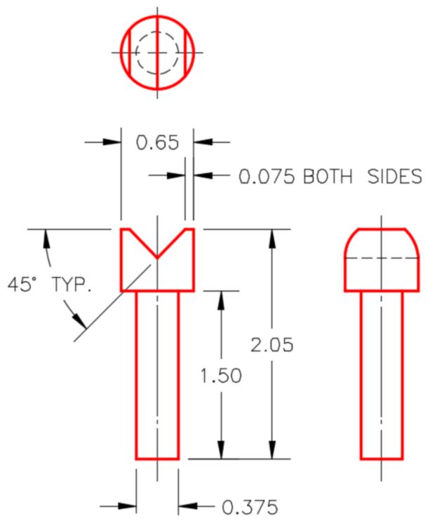
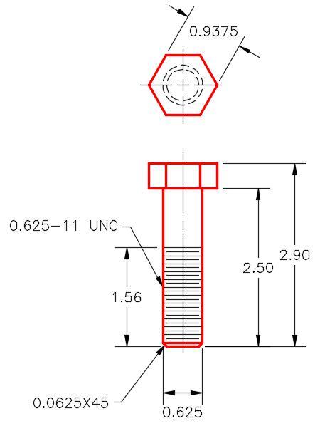
Part: Set Screw
Part Name: Inventor Lab 26-1E
Template: English-Modules Part (in).ipt
Color: Steel – Polished
Material: Steel (Figure Step 1L, 1M, and 1N)
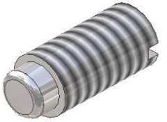
Solid Model –
Home View
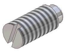
Solid Model –
Orbited View
Figure
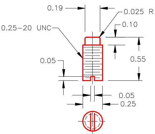
Dimensioned Multiview Drawing
Part: Bolt
Part Name: Inventor Lab 26-1F
Template: English-Modules Part (in).ipt
Color: Metal-AL-6061 – Machined
Material: Steel (Figure Step 1P and 1Q)
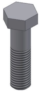
Solid Model –
Home View
Dimensioned Multiview Drawing
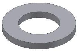
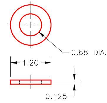
Part: Washer
Part Name: Inventor Lab 26-1G
Template: English-Modules Part (in).ipt
Color: Metal-AL-6061 – Machined
Material: Steel (Figure Step 1R and 1S)
Solid Model –
Home View
Dimensioned Multiview Drawing
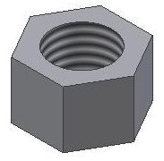
Part: Nut
Part Name: Inventor Lab 26-1H
Template: English-Modules Part (in).ipt
Color: Metal-AL-6061 – Machined
Material: Steel (Figure Step 1T and 1U)
Solid Model –
Home View
Dimensioned Multiview Drawing
Competency
Step 2
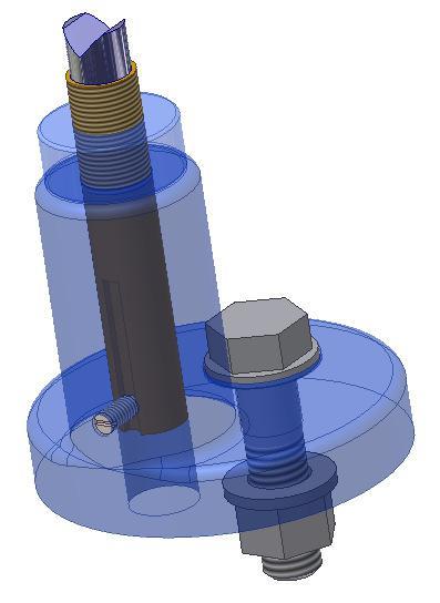
Assemble the parts that you created in Step 1 to create the Machine Jack assembly as shown in figures below. There are two washers, one above and one below the base. The washer under the base should be assembled with 0.5 inches offset from the bottom of the base. Save the assembly using the following name:
Assembly: Machine Jack
Assembly Name: Inventor Lab 26-2A
Template: English-Modules Assembly (in).iam (Figure Step 2A and 2B)
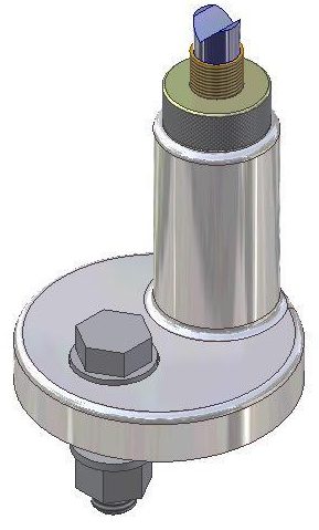
Assembled Solid Model –
Home View
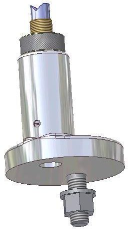
Assembled Solid Model –
Orbited View
Step 3
With the assembly file: Inventor Lab 26-2A.iam as the active file, save a copy of it naming it: Inventor Lab 26-2B.iam.
Step 4
Open the assembly file: Inventor Lab 26-2B.iam that you just copied. Change the colour of the Base and the Adjusting Nut in the assembly file to Clear – Blue as shown in the figures below.
Assembly: Machine Jack
Assembly Name: Inventor Lab 26-2B
Template: N/A (Figure Step 4A and 4B)
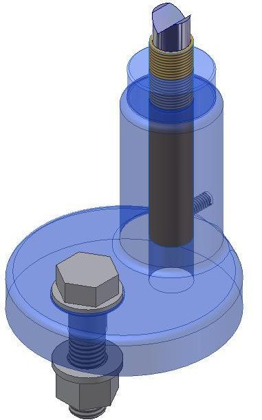
Assembled Solid Model –
Home View
Assembled Solid Model –
Orbited View
Step 5
Create a presentation file using the assembly file Inventor Lab 26-2A. Tweak it to match as close as you can to Figure Step 5.
Step 6
Set the animation Interval to 20 and the Repetitions to 2. Test the animation.
Presentation: Machine Jack
Presentation Name: Inventor Lab 26-2A
Template: N/A
Step 7
Create the following drawing as follows:
A Create one drawing file complete with two sheets as shown in Figure 4A, 4B and Figure 7A, 7B.
B Create the same views shown in the drawings.
C If the scale is not indicated, set it to full scale or 1:1.
D Save the drawing file with the drawing name: Inventor Lab 26-1.idw Figure Step 5
E Complete the titleblock in both drawings sheets.
Drawing Name: Inventor Lab 26-1.idw
Template: English-Modules Drawing ANSI (in).idw
Sheet: 1
Part: Base
Drawing Size: C
Part Name: Inventor Lab 26-1A.ipt (Figure Step 7A and 7B)
Sheet: 2
Part: Post
Drawing Size: A
Part Name: Inventor Lab 26-1D.ipt (Figure Step 7C and 7D)