
7.4: Reading- Telecommunications Network
- Page ID
- 18661
\( \newcommand{\vecs}[1]{\overset { \scriptstyle \rightharpoonup} {\mathbf{#1}} } \)
\( \newcommand{\vecd}[1]{\overset{-\!-\!\rightharpoonup}{\vphantom{a}\smash {#1}}} \)
\( \newcommand{\id}{\mathrm{id}}\) \( \newcommand{\Span}{\mathrm{span}}\)
( \newcommand{\kernel}{\mathrm{null}\,}\) \( \newcommand{\range}{\mathrm{range}\,}\)
\( \newcommand{\RealPart}{\mathrm{Re}}\) \( \newcommand{\ImaginaryPart}{\mathrm{Im}}\)
\( \newcommand{\Argument}{\mathrm{Arg}}\) \( \newcommand{\norm}[1]{\| #1 \|}\)
\( \newcommand{\inner}[2]{\langle #1, #2 \rangle}\)
\( \newcommand{\Span}{\mathrm{span}}\)
\( \newcommand{\id}{\mathrm{id}}\)
\( \newcommand{\Span}{\mathrm{span}}\)
\( \newcommand{\kernel}{\mathrm{null}\,}\)
\( \newcommand{\range}{\mathrm{range}\,}\)
\( \newcommand{\RealPart}{\mathrm{Re}}\)
\( \newcommand{\ImaginaryPart}{\mathrm{Im}}\)
\( \newcommand{\Argument}{\mathrm{Arg}}\)
\( \newcommand{\norm}[1]{\| #1 \|}\)
\( \newcommand{\inner}[2]{\langle #1, #2 \rangle}\)
\( \newcommand{\Span}{\mathrm{span}}\) \( \newcommand{\AA}{\unicode[.8,0]{x212B}}\)
\( \newcommand{\vectorA}[1]{\vec{#1}} % arrow\)
\( \newcommand{\vectorAt}[1]{\vec{\text{#1}}} % arrow\)
\( \newcommand{\vectorB}[1]{\overset { \scriptstyle \rightharpoonup} {\mathbf{#1}} } \)
\( \newcommand{\vectorC}[1]{\textbf{#1}} \)
\( \newcommand{\vectorD}[1]{\overrightarrow{#1}} \)
\( \newcommand{\vectorDt}[1]{\overrightarrow{\text{#1}}} \)
\( \newcommand{\vectE}[1]{\overset{-\!-\!\rightharpoonup}{\vphantom{a}\smash{\mathbf {#1}}}} \)
\( \newcommand{\vecs}[1]{\overset { \scriptstyle \rightharpoonup} {\mathbf{#1}} } \)
\( \newcommand{\vecd}[1]{\overset{-\!-\!\rightharpoonup}{\vphantom{a}\smash {#1}}} \)
\(\newcommand{\avec}{\mathbf a}\) \(\newcommand{\bvec}{\mathbf b}\) \(\newcommand{\cvec}{\mathbf c}\) \(\newcommand{\dvec}{\mathbf d}\) \(\newcommand{\dtil}{\widetilde{\mathbf d}}\) \(\newcommand{\evec}{\mathbf e}\) \(\newcommand{\fvec}{\mathbf f}\) \(\newcommand{\nvec}{\mathbf n}\) \(\newcommand{\pvec}{\mathbf p}\) \(\newcommand{\qvec}{\mathbf q}\) \(\newcommand{\svec}{\mathbf s}\) \(\newcommand{\tvec}{\mathbf t}\) \(\newcommand{\uvec}{\mathbf u}\) \(\newcommand{\vvec}{\mathbf v}\) \(\newcommand{\wvec}{\mathbf w}\) \(\newcommand{\xvec}{\mathbf x}\) \(\newcommand{\yvec}{\mathbf y}\) \(\newcommand{\zvec}{\mathbf z}\) \(\newcommand{\rvec}{\mathbf r}\) \(\newcommand{\mvec}{\mathbf m}\) \(\newcommand{\zerovec}{\mathbf 0}\) \(\newcommand{\onevec}{\mathbf 1}\) \(\newcommand{\real}{\mathbb R}\) \(\newcommand{\twovec}[2]{\left[\begin{array}{r}#1 \\ #2 \end{array}\right]}\) \(\newcommand{\ctwovec}[2]{\left[\begin{array}{c}#1 \\ #2 \end{array}\right]}\) \(\newcommand{\threevec}[3]{\left[\begin{array}{r}#1 \\ #2 \\ #3 \end{array}\right]}\) \(\newcommand{\cthreevec}[3]{\left[\begin{array}{c}#1 \\ #2 \\ #3 \end{array}\right]}\) \(\newcommand{\fourvec}[4]{\left[\begin{array}{r}#1 \\ #2 \\ #3 \\ #4 \end{array}\right]}\) \(\newcommand{\cfourvec}[4]{\left[\begin{array}{c}#1 \\ #2 \\ #3 \\ #4 \end{array}\right]}\) \(\newcommand{\fivevec}[5]{\left[\begin{array}{r}#1 \\ #2 \\ #3 \\ #4 \\ #5 \\ \end{array}\right]}\) \(\newcommand{\cfivevec}[5]{\left[\begin{array}{c}#1 \\ #2 \\ #3 \\ #4 \\ #5 \\ \end{array}\right]}\) \(\newcommand{\mattwo}[4]{\left[\begin{array}{rr}#1 \amp #2 \\ #3 \amp #4 \\ \end{array}\right]}\) \(\newcommand{\laspan}[1]{\text{Span}\{#1\}}\) \(\newcommand{\bcal}{\cal B}\) \(\newcommand{\ccal}{\cal C}\) \(\newcommand{\scal}{\cal S}\) \(\newcommand{\wcal}{\cal W}\) \(\newcommand{\ecal}{\cal E}\) \(\newcommand{\coords}[2]{\left\{#1\right\}_{#2}}\) \(\newcommand{\gray}[1]{\color{gray}{#1}}\) \(\newcommand{\lgray}[1]{\color{lightgray}{#1}}\) \(\newcommand{\rank}{\operatorname{rank}}\) \(\newcommand{\row}{\text{Row}}\) \(\newcommand{\col}{\text{Col}}\) \(\renewcommand{\row}{\text{Row}}\) \(\newcommand{\nul}{\text{Nul}}\) \(\newcommand{\var}{\text{Var}}\) \(\newcommand{\corr}{\text{corr}}\) \(\newcommand{\len}[1]{\left|#1\right|}\) \(\newcommand{\bbar}{\overline{\bvec}}\) \(\newcommand{\bhat}{\widehat{\bvec}}\) \(\newcommand{\bperp}{\bvec^\perp}\) \(\newcommand{\xhat}{\widehat{\xvec}}\) \(\newcommand{\vhat}{\widehat{\vvec}}\) \(\newcommand{\uhat}{\widehat{\uvec}}\) \(\newcommand{\what}{\widehat{\wvec}}\) \(\newcommand{\Sighat}{\widehat{\Sigma}}\) \(\newcommand{\lt}{<}\) \(\newcommand{\gt}{>}\) \(\newcommand{\amp}{&}\) \(\definecolor{fillinmathshade}{gray}{0.9}\)Introduction
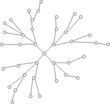
A telecommunications network is a collection of terminal nodes, links and any intermediate nodes which are connected so as to enable telecommunication between the terminals.
The transmission links connect the nodes together. The nodes use circuit switching, message switching or packet switching to pass the signal through the correct links and nodes to reach the correct destination terminal.
Each terminal in the network usually has a unique address so messages or connections can be routed to the correct recipients. The collection of addresses in the network is called the address space.
Examples of telecommunications networks are:
- computer networks
- the Internet
- the telephone network
- the global Telex network
- the aeronautical ACARS network
Benefits of Telecommunications and Networking
Telecommunications can greatly increase and expand resources to all types of people. For example, businesses need a greater telecommunications network if they plan to expand their company. With Internet, computer, and telephone networks, businesses can allocate their resources efficiently. These core types of networks will be discussed below:
Computer Network: A computer network consists of computers and devices connected to one another. Information can be transferred from one device to the next. For example, an office filled with computers can share files together on each separate device. Computer networks can range from a local network area to a wide area network. The difference between the types of networks is the size. These types of computer networks work at certain speeds, also known as broadband. The Internet network can connect computer worldwide.
Internet Network: Access to the network allows users to use many resources. Over time the Internet network will replace books. This will enable users to discover information almost instantly and apply concepts to different situations. The Internet can be used for recreational, governmental, educational, and other purposes. Businesses in particular use the Internet network for research or to service customers and clients.
Telephone Network: The telephone network connects people to one another. This network can be used in a variety of ways. Many businesses use the telephone network to route calls and/or service their customers. Some businesses use a telephone network on a greater scale through a private branch exchange. It is a system where a specific business focuses on routing and servicing calls for another business. Majority of the time, the telephone network is used around the world for recreational purposes.
Network structure
In general, every telecommunications network conceptually consists of three parts, or planes (so called because they can be thought of as being, and often are, separate overlay networks):
- The control plane carries control information (also known as signalling).
- The data plane or user plane or bearer plane carries the network’s users traffic.
- The management plane carries the operations and administration traffic required for network management.
Example: the TCP/IP data network
The data network is used extensively throughout the world to connect individuals and organizations. Data networks can be connected to allow users seamless access to resources that are hosted outside of the particular provider they are connected to. The Internet is the best example of many data networks from different organizations all operating under a single address space.
Terminals attached to TCP/IP networks are addressed using IP addresses. There are different types of IP address, but the most common is IP Version 4. Each unique address consists of 4 integers between 0 and 255, usually separated by dots when written down, e.g. 82.131.34.56.
TCP/IP are the fundamental protocols that provide the control and routing of messages across the data network. There are many different network structures that TCP/IP can be used across to efficiently route messages, for example:
- wide area networks (WAN)
- metropolitan area networks (MAN)
- local area networks (LAN)
- Internet area networks (IAN)
- campus area networks (CAN)
- virtual private networks (VPN)
There are three features that differentiate MANs from LANs or WANs:
- The area of the network size is between LANs and WANs. The MAN will have a physical area between 5 and 50 km in diameter.
- MANs do not generally belong to a single organization. The equipment that interconnects the network, the links, and the MAN itself are often owned by an association or a network provider that provides or leases the service to others.
- A MAN is a means for sharing resources at high speeds within the network. It often provide connections to WAN networks for access to resources outside the scope of the MAN.
Optical Transport Network (OTN)
Optical Transport Network (OTN) is a large complex network of server hubs at different locations on ground, connected by Optical fiber cable or optical network carrier, to transport data across different nodes. The server hubs are also known as head-ends, nodes or simply, sites. OTNs are the backbone of Internet Service Providers and are often daisy chained and cross connected to provide network redundancy. Such a setup facilitates uninterrupted services and fail-over capabilities during maintenance windows, equipment failure or in case of accidents.
The devices used to transport data are known as network transport equipment. Some of the widely used equipment are manufactured by
- Alcatel Lucent – AL7510, AL7750
- Nortel Networks Corp. (acquired by Ciena Corp.) – Optera Metro series – OM4500, OM6500
- Fujitsu Ltd. – FlashWave series FW4500, FW7500, FW9500
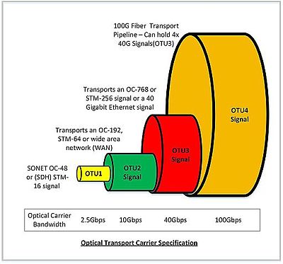
The capacity of a network is mainly dependent on the type of signaling scheme employed on transmitting and receiving end. In the earlier days, a single wavelength light beam was used to transmit data, which limited the bandwidth to the maximum operating frequency of the transmitting and receiving end equipment. With the application of wavelength division multiplexing (WDM), the bandwidth of OTN has risen up to 100Gbit/s (OTU4 Signal), by emitting light beams of different wavelengths. Lately, AT&T, Verizon, and Rogers Communication have been able to employ these 100G “pipes” in their metro network. Large field areas are mostly serviced by 40G pipes (OC192/STM-64).
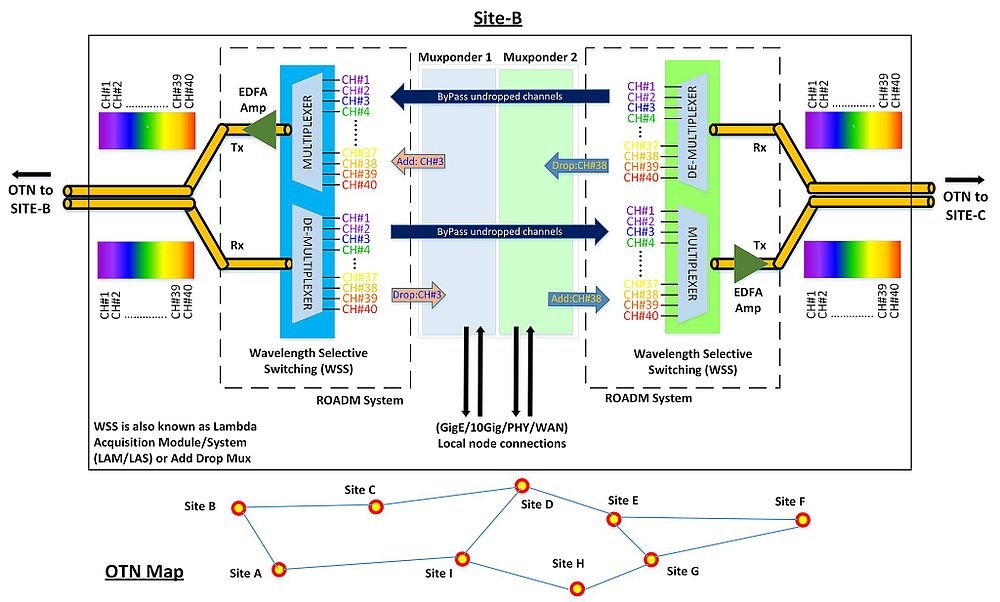
A 40G pipe can carry 40 different channels as a result of Dense Wave Division Multiplexing (DWDM) transmission. Each node in the network is able to access different channels, but is mostly tuned to a few channels. The data from a channel can be dropped to the node or new data can be added to the node using Re-configurable Optic Add Drop Mux (ROADM) that uses Wavelength Selective Switching (WSS) to extract and infuse a configured frequency. This eliminates the need to convert all the channels to electric signals, extract the required channels, and convert the rest back to optical into the OTN. Thus ROADM systems are fast, less expensive and can be configured to access any channel in the OTN pipe.
The extracted channels at a site are connected to local devices through muxponder or tranponder cards that can split or combine 40G channels to 4x 10G channels or 8x 2.5G channels.
- Telecommunications network. Provided by: Wikipedia. Located at: https://en.wikipedia.org/wiki/Telecommunications_network. License: CC BY-SA: Attribution-ShareAlike
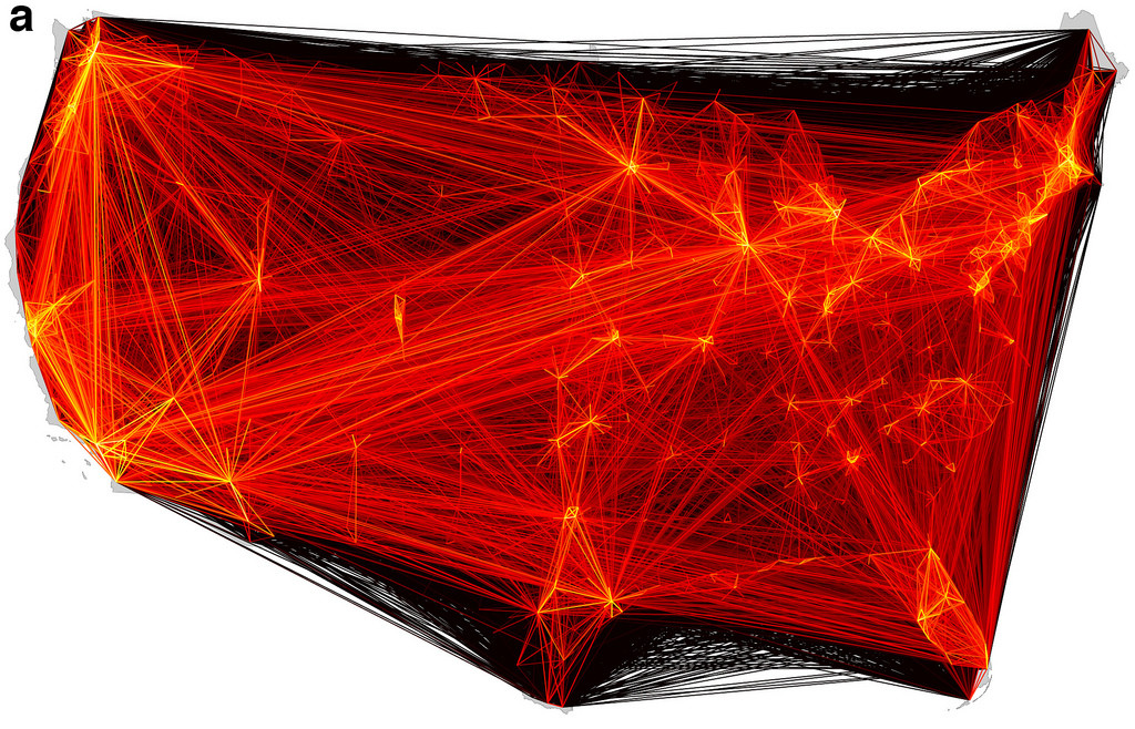
- Human mobility network derived from bank note fluxes via Christian Thiemann et al. Authored by: Duncan Hill. Located at: https://www.flickr.com/photos/dullhunk/5221572088/. License: CC BY: Attribution