1.4: Module 4 - Solid Modelling II
- Page ID
- 25070

\( \newcommand{\vecs}[1]{\overset { \scriptstyle \rightharpoonup} {\mathbf{#1}} } \)
\( \newcommand{\vecd}[1]{\overset{-\!-\!\rightharpoonup}{\vphantom{a}\smash {#1}}} \)
\( \newcommand{\dsum}{\displaystyle\sum\limits} \)
\( \newcommand{\dint}{\displaystyle\int\limits} \)
\( \newcommand{\dlim}{\displaystyle\lim\limits} \)
\( \newcommand{\id}{\mathrm{id}}\) \( \newcommand{\Span}{\mathrm{span}}\)
( \newcommand{\kernel}{\mathrm{null}\,}\) \( \newcommand{\range}{\mathrm{range}\,}\)
\( \newcommand{\RealPart}{\mathrm{Re}}\) \( \newcommand{\ImaginaryPart}{\mathrm{Im}}\)
\( \newcommand{\Argument}{\mathrm{Arg}}\) \( \newcommand{\norm}[1]{\| #1 \|}\)
\( \newcommand{\inner}[2]{\langle #1, #2 \rangle}\)
\( \newcommand{\Span}{\mathrm{span}}\)
\( \newcommand{\id}{\mathrm{id}}\)
\( \newcommand{\Span}{\mathrm{span}}\)
\( \newcommand{\kernel}{\mathrm{null}\,}\)
\( \newcommand{\range}{\mathrm{range}\,}\)
\( \newcommand{\RealPart}{\mathrm{Re}}\)
\( \newcommand{\ImaginaryPart}{\mathrm{Im}}\)
\( \newcommand{\Argument}{\mathrm{Arg}}\)
\( \newcommand{\norm}[1]{\| #1 \|}\)
\( \newcommand{\inner}[2]{\langle #1, #2 \rangle}\)
\( \newcommand{\Span}{\mathrm{span}}\) \( \newcommand{\AA}{\unicode[.8,0]{x212B}}\)
\( \newcommand{\vectorA}[1]{\vec{#1}} % arrow\)
\( \newcommand{\vectorAt}[1]{\vec{\text{#1}}} % arrow\)
\( \newcommand{\vectorB}[1]{\overset { \scriptstyle \rightharpoonup} {\mathbf{#1}} } \)
\( \newcommand{\vectorC}[1]{\textbf{#1}} \)
\( \newcommand{\vectorD}[1]{\overrightarrow{#1}} \)
\( \newcommand{\vectorDt}[1]{\overrightarrow{\text{#1}}} \)
\( \newcommand{\vectE}[1]{\overset{-\!-\!\rightharpoonup}{\vphantom{a}\smash{\mathbf {#1}}}} \)
\( \newcommand{\vecs}[1]{\overset { \scriptstyle \rightharpoonup} {\mathbf{#1}} } \)
\(\newcommand{\longvect}{\overrightarrow}\)
\( \newcommand{\vecd}[1]{\overset{-\!-\!\rightharpoonup}{\vphantom{a}\smash {#1}}} \)
\(\newcommand{\avec}{\mathbf a}\) \(\newcommand{\bvec}{\mathbf b}\) \(\newcommand{\cvec}{\mathbf c}\) \(\newcommand{\dvec}{\mathbf d}\) \(\newcommand{\dtil}{\widetilde{\mathbf d}}\) \(\newcommand{\evec}{\mathbf e}\) \(\newcommand{\fvec}{\mathbf f}\) \(\newcommand{\nvec}{\mathbf n}\) \(\newcommand{\pvec}{\mathbf p}\) \(\newcommand{\qvec}{\mathbf q}\) \(\newcommand{\svec}{\mathbf s}\) \(\newcommand{\tvec}{\mathbf t}\) \(\newcommand{\uvec}{\mathbf u}\) \(\newcommand{\vvec}{\mathbf v}\) \(\newcommand{\wvec}{\mathbf w}\) \(\newcommand{\xvec}{\mathbf x}\) \(\newcommand{\yvec}{\mathbf y}\) \(\newcommand{\zvec}{\mathbf z}\) \(\newcommand{\rvec}{\mathbf r}\) \(\newcommand{\mvec}{\mathbf m}\) \(\newcommand{\zerovec}{\mathbf 0}\) \(\newcommand{\onevec}{\mathbf 1}\) \(\newcommand{\real}{\mathbb R}\) \(\newcommand{\twovec}[2]{\left[\begin{array}{r}#1 \\ #2 \end{array}\right]}\) \(\newcommand{\ctwovec}[2]{\left[\begin{array}{c}#1 \\ #2 \end{array}\right]}\) \(\newcommand{\threevec}[3]{\left[\begin{array}{r}#1 \\ #2 \\ #3 \end{array}\right]}\) \(\newcommand{\cthreevec}[3]{\left[\begin{array}{c}#1 \\ #2 \\ #3 \end{array}\right]}\) \(\newcommand{\fourvec}[4]{\left[\begin{array}{r}#1 \\ #2 \\ #3 \\ #4 \end{array}\right]}\) \(\newcommand{\cfourvec}[4]{\left[\begin{array}{c}#1 \\ #2 \\ #3 \\ #4 \end{array}\right]}\) \(\newcommand{\fivevec}[5]{\left[\begin{array}{r}#1 \\ #2 \\ #3 \\ #4 \\ #5 \\ \end{array}\right]}\) \(\newcommand{\cfivevec}[5]{\left[\begin{array}{c}#1 \\ #2 \\ #3 \\ #4 \\ #5 \\ \end{array}\right]}\) \(\newcommand{\mattwo}[4]{\left[\begin{array}{rr}#1 \amp #2 \\ #3 \amp #4 \\ \end{array}\right]}\) \(\newcommand{\laspan}[1]{\text{Span}\{#1\}}\) \(\newcommand{\bcal}{\cal B}\) \(\newcommand{\ccal}{\cal C}\) \(\newcommand{\scal}{\cal S}\) \(\newcommand{\wcal}{\cal W}\) \(\newcommand{\ecal}{\cal E}\) \(\newcommand{\coords}[2]{\left\{#1\right\}_{#2}}\) \(\newcommand{\gray}[1]{\color{gray}{#1}}\) \(\newcommand{\lgray}[1]{\color{lightgray}{#1}}\) \(\newcommand{\rank}{\operatorname{rank}}\) \(\newcommand{\row}{\text{Row}}\) \(\newcommand{\col}{\text{Col}}\) \(\renewcommand{\row}{\text{Row}}\) \(\newcommand{\nul}{\text{Nul}}\) \(\newcommand{\var}{\text{Var}}\) \(\newcommand{\corr}{\text{corr}}\) \(\newcommand{\len}[1]{\left|#1\right|}\) \(\newcommand{\bbar}{\overline{\bvec}}\) \(\newcommand{\bhat}{\widehat{\bvec}}\) \(\newcommand{\bperp}{\bvec^\perp}\) \(\newcommand{\xhat}{\widehat{\xvec}}\) \(\newcommand{\vhat}{\widehat{\vvec}}\) \(\newcommand{\uhat}{\widehat{\uvec}}\) \(\newcommand{\what}{\widehat{\wvec}}\) \(\newcommand{\Sighat}{\widehat{\Sigma}}\) \(\newcommand{\lt}{<}\) \(\newcommand{\gt}{>}\) \(\newcommand{\amp}{&}\) \(\definecolor{fillinmathshade}{gray}{0.9}\)Introduction
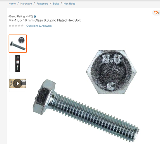
This module touches on some more complex features available in the solid modeling toolbox. Let’s say you want to add a commercially available fastener component on your drawing. Go to the website of a hardware store and there is usually a drawing or even a CAD model of the fastener. This exercise walks through the steps to generate a CAD model for an M7 hex bolt.
Module 4 - step-by-step video
Steps to create an M7 hex bolt model:
Step 1 - Create new sketch
Start a new sketch. Make sure the units are in millimeters (mm).
Step 2- Draw a circle
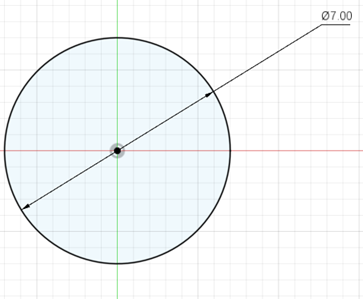
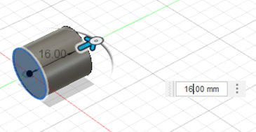
On the front plane draw a circle of diameter 7 mm. Then click Finish Sketch. (See Figure \(\PageIndex{3}\).)
Step 3 - Extrude circle
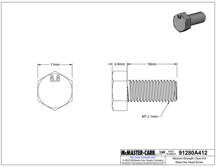
From the Create menu select Extrude to create a cylinder using the circle that was just sketched. The extrude length is 16 mm. (See Figure \(\PageIndex{4}\).)
Step 4 - Create threads
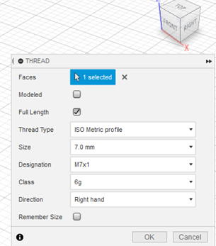
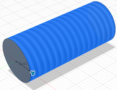
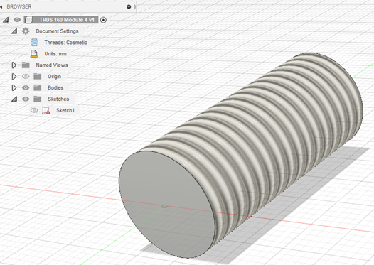
From the Create menu, select Threads. Select the surface of the cylinder as shown in the images below. The size of the threads are the same as the diameter and the designation is M7 x 1 (1 mm being the pitch and 7 mm being the diameter). 6g is the tolerance and the direction of the thread is right-handed. This step will produce threads on the stem of the bolt. (See Figures \(\PageIndex{5}\), \(\PageIndex{6}\), and \(\PageIndex{7}\).)
Step 5 - Sketch a polygon
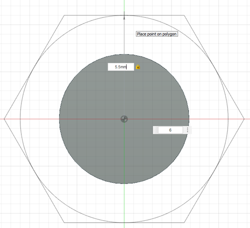
Now, to create the head of the hex bolt sketch a hexagon on either face of the cylinder as shown in the image below. Inside the sketch menu, select Polygon > Circumscribed Polygon. There are 6 sides to the polygon (making it a hexagon); the radius of the circle inscribed inside the hexagon is 5.5 mm. (See Figure \(\PageIndex{8}\).)
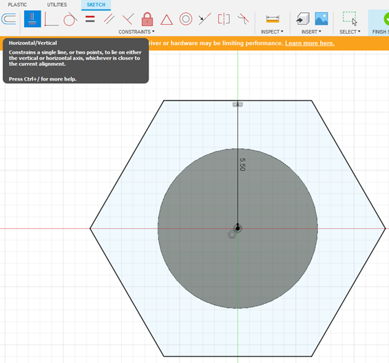
Step 6 - Fix the sketch
Best Practice: To fix this Sketch, apply a horizontal constraint to one of the two horizontal sides of the hexagon. This is shown in Figure \(\PageIndex{9}\) below.
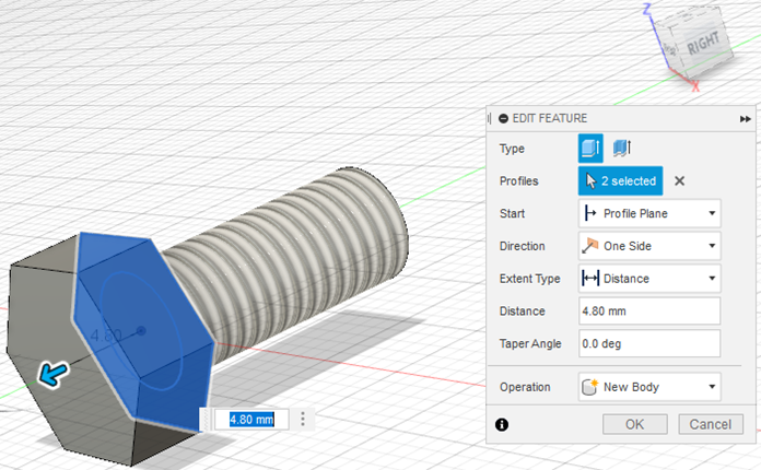
Step 7 - Extrude hexagon
To form the head of the hex bolt, Create > Extrude the hexagon sketch that has been created in the previous step. The extrude length is 4.8 mm as shown in Figure \(\PageIndex{10}\) below. Make sure you select “New Body” in the Extrude menu.
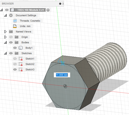
Step 8 - Sketch a circle on the hex head
In order to create the chamfers on the hex head, do this: sketch a circle of diameter 11 mm on the top face of the hex head as shown in Figure \(\PageIndex{11}\)below.
Step 9 - Extrude chamfer
After the sketch, got to Create > Extrude and extrude out this sketch as per the parameters shown in dialog box in Figure \(\PageIndex{12}\) below. Extrude out the sketch to a distance of -4.80 mm, and with a taper angle of 45.0 deg. Make sure the type of Operation selected is Intersect.
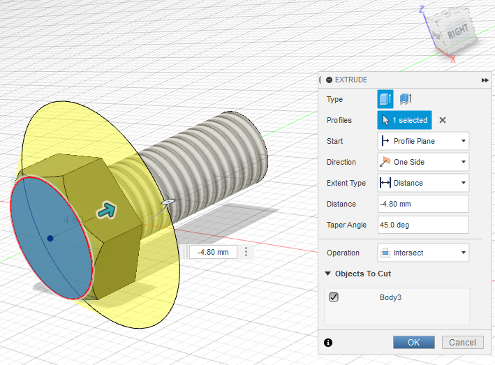
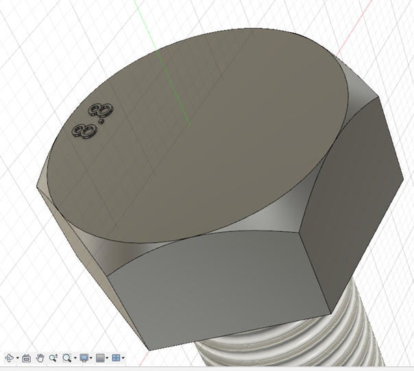
At this point, the bolt head should look like the following Figure \(\PageIndex{13}\).
Step 10 - Sketch text on hex head
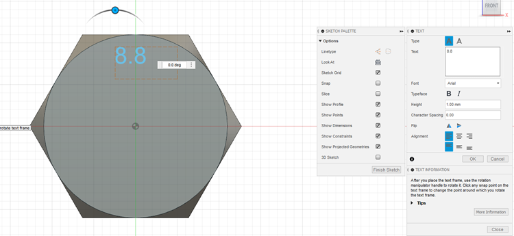
To write “8.8” on the hex head, select the top surface of the hex head and sketch on it. Go to Create > Sketch. Write “8.8” on the head of the hex head. The height of this text box is 1.00 mm and is placed approximately close (eyeball this, no precise location needed) to one of the edge of the hexagon. This is shown in Figure \(\PageIndex{14}\) and Figure \(\PageIndex{15}\) below.
Step 11 - Emboss text
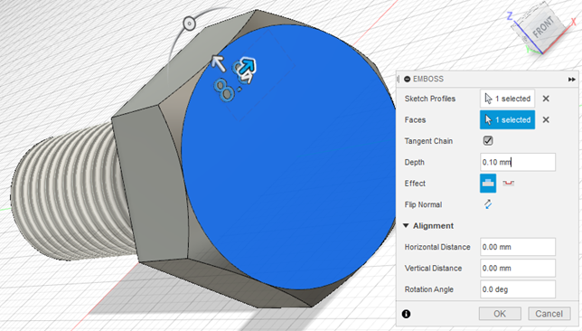
Now, go to Create > Emboss and select “8.8” to emboss. The height of this feature is 0.10 mm. (See Figure \(\PageIndex{15}\).)
Outcome
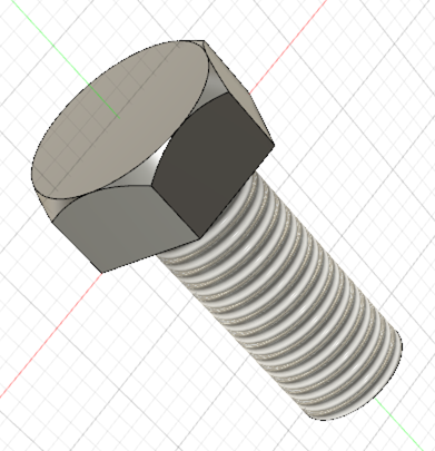
You have successfully created the M7 – 1.0 x 16 mm metric bolt. It should look like the image below (Figure \(\PageIndex{16}\)), exactly similar to the Home Depot website, and McMaster Carr website. Remember to save your work.