
1.6: Module 5 - Assembly
- Page ID
- 25071

\( \newcommand{\vecs}[1]{\overset { \scriptstyle \rightharpoonup} {\mathbf{#1}} } \)
\( \newcommand{\vecd}[1]{\overset{-\!-\!\rightharpoonup}{\vphantom{a}\smash {#1}}} \)
\( \newcommand{\dsum}{\displaystyle\sum\limits} \)
\( \newcommand{\dint}{\displaystyle\int\limits} \)
\( \newcommand{\dlim}{\displaystyle\lim\limits} \)
\( \newcommand{\id}{\mathrm{id}}\) \( \newcommand{\Span}{\mathrm{span}}\)
( \newcommand{\kernel}{\mathrm{null}\,}\) \( \newcommand{\range}{\mathrm{range}\,}\)
\( \newcommand{\RealPart}{\mathrm{Re}}\) \( \newcommand{\ImaginaryPart}{\mathrm{Im}}\)
\( \newcommand{\Argument}{\mathrm{Arg}}\) \( \newcommand{\norm}[1]{\| #1 \|}\)
\( \newcommand{\inner}[2]{\langle #1, #2 \rangle}\)
\( \newcommand{\Span}{\mathrm{span}}\)
\( \newcommand{\id}{\mathrm{id}}\)
\( \newcommand{\Span}{\mathrm{span}}\)
\( \newcommand{\kernel}{\mathrm{null}\,}\)
\( \newcommand{\range}{\mathrm{range}\,}\)
\( \newcommand{\RealPart}{\mathrm{Re}}\)
\( \newcommand{\ImaginaryPart}{\mathrm{Im}}\)
\( \newcommand{\Argument}{\mathrm{Arg}}\)
\( \newcommand{\norm}[1]{\| #1 \|}\)
\( \newcommand{\inner}[2]{\langle #1, #2 \rangle}\)
\( \newcommand{\Span}{\mathrm{span}}\) \( \newcommand{\AA}{\unicode[.8,0]{x212B}}\)
\( \newcommand{\vectorA}[1]{\vec{#1}} % arrow\)
\( \newcommand{\vectorAt}[1]{\vec{\text{#1}}} % arrow\)
\( \newcommand{\vectorB}[1]{\overset { \scriptstyle \rightharpoonup} {\mathbf{#1}} } \)
\( \newcommand{\vectorC}[1]{\textbf{#1}} \)
\( \newcommand{\vectorD}[1]{\overrightarrow{#1}} \)
\( \newcommand{\vectorDt}[1]{\overrightarrow{\text{#1}}} \)
\( \newcommand{\vectE}[1]{\overset{-\!-\!\rightharpoonup}{\vphantom{a}\smash{\mathbf {#1}}}} \)
\( \newcommand{\vecs}[1]{\overset { \scriptstyle \rightharpoonup} {\mathbf{#1}} } \)
\(\newcommand{\longvect}{\overrightarrow}\)
\( \newcommand{\vecd}[1]{\overset{-\!-\!\rightharpoonup}{\vphantom{a}\smash {#1}}} \)
\(\newcommand{\avec}{\mathbf a}\) \(\newcommand{\bvec}{\mathbf b}\) \(\newcommand{\cvec}{\mathbf c}\) \(\newcommand{\dvec}{\mathbf d}\) \(\newcommand{\dtil}{\widetilde{\mathbf d}}\) \(\newcommand{\evec}{\mathbf e}\) \(\newcommand{\fvec}{\mathbf f}\) \(\newcommand{\nvec}{\mathbf n}\) \(\newcommand{\pvec}{\mathbf p}\) \(\newcommand{\qvec}{\mathbf q}\) \(\newcommand{\svec}{\mathbf s}\) \(\newcommand{\tvec}{\mathbf t}\) \(\newcommand{\uvec}{\mathbf u}\) \(\newcommand{\vvec}{\mathbf v}\) \(\newcommand{\wvec}{\mathbf w}\) \(\newcommand{\xvec}{\mathbf x}\) \(\newcommand{\yvec}{\mathbf y}\) \(\newcommand{\zvec}{\mathbf z}\) \(\newcommand{\rvec}{\mathbf r}\) \(\newcommand{\mvec}{\mathbf m}\) \(\newcommand{\zerovec}{\mathbf 0}\) \(\newcommand{\onevec}{\mathbf 1}\) \(\newcommand{\real}{\mathbb R}\) \(\newcommand{\twovec}[2]{\left[\begin{array}{r}#1 \\ #2 \end{array}\right]}\) \(\newcommand{\ctwovec}[2]{\left[\begin{array}{c}#1 \\ #2 \end{array}\right]}\) \(\newcommand{\threevec}[3]{\left[\begin{array}{r}#1 \\ #2 \\ #3 \end{array}\right]}\) \(\newcommand{\cthreevec}[3]{\left[\begin{array}{c}#1 \\ #2 \\ #3 \end{array}\right]}\) \(\newcommand{\fourvec}[4]{\left[\begin{array}{r}#1 \\ #2 \\ #3 \\ #4 \end{array}\right]}\) \(\newcommand{\cfourvec}[4]{\left[\begin{array}{c}#1 \\ #2 \\ #3 \\ #4 \end{array}\right]}\) \(\newcommand{\fivevec}[5]{\left[\begin{array}{r}#1 \\ #2 \\ #3 \\ #4 \\ #5 \\ \end{array}\right]}\) \(\newcommand{\cfivevec}[5]{\left[\begin{array}{c}#1 \\ #2 \\ #3 \\ #4 \\ #5 \\ \end{array}\right]}\) \(\newcommand{\mattwo}[4]{\left[\begin{array}{rr}#1 \amp #2 \\ #3 \amp #4 \\ \end{array}\right]}\) \(\newcommand{\laspan}[1]{\text{Span}\{#1\}}\) \(\newcommand{\bcal}{\cal B}\) \(\newcommand{\ccal}{\cal C}\) \(\newcommand{\scal}{\cal S}\) \(\newcommand{\wcal}{\cal W}\) \(\newcommand{\ecal}{\cal E}\) \(\newcommand{\coords}[2]{\left\{#1\right\}_{#2}}\) \(\newcommand{\gray}[1]{\color{gray}{#1}}\) \(\newcommand{\lgray}[1]{\color{lightgray}{#1}}\) \(\newcommand{\rank}{\operatorname{rank}}\) \(\newcommand{\row}{\text{Row}}\) \(\newcommand{\col}{\text{Col}}\) \(\renewcommand{\row}{\text{Row}}\) \(\newcommand{\nul}{\text{Nul}}\) \(\newcommand{\var}{\text{Var}}\) \(\newcommand{\corr}{\text{corr}}\) \(\newcommand{\len}[1]{\left|#1\right|}\) \(\newcommand{\bbar}{\overline{\bvec}}\) \(\newcommand{\bhat}{\widehat{\bvec}}\) \(\newcommand{\bperp}{\bvec^\perp}\) \(\newcommand{\xhat}{\widehat{\xvec}}\) \(\newcommand{\vhat}{\widehat{\vvec}}\) \(\newcommand{\uhat}{\widehat{\uvec}}\) \(\newcommand{\what}{\widehat{\wvec}}\) \(\newcommand{\Sighat}{\widehat{\Sigma}}\) \(\newcommand{\lt}{<}\) \(\newcommand{\gt}{>}\) \(\newcommand{\amp}{&}\) \(\definecolor{fillinmathshade}{gray}{0.9}\)Introduction
Autodesk Fusion 360 allows for the assembly of multiple 3D components to form a new system of components. This system is referred to as an assembly or subassembly.
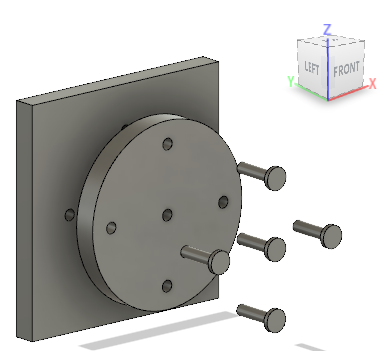
As an example, we will assemble a square base plate and a circular plate using five (5) pins as shown in Figure \(\PageIndex{1}\).
Module 5 video showing Assembly options
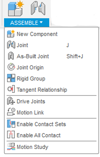
Assembly Options
To assemble various components together, there are a few options available. Some of the more frequently used are discussed in the sections below and are shown in Figure \(\PageIndex{2}\).
New Component
The New Component tool allows for adding a component or creating a new component that will be used in the assembly.
Joint
The Joint tool allows for adding various components relative to each other in the assembly and also specify relative motion between these components. (See Figure \(\PageIndex{3}\).)
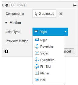
Joint Type options for the Joint are as follows:
- Rigid locks all components together and removes all degrees of freedom.
- Revolute rotates the component around the joint origin.
- Slides allows for sliding a component along an axis.
- Cylindrical rotates and slides a component on a single axis.
- Pin Slot rotates and sides the component on two different axes.
- Planar rotates a component around one axis normal to a plane and slides it along two axes parallel to the plane.
- Ball rotates a component on all three axes on a gimbal system.
We will only use the “rigid” option today and do a quick demo to understand what other options are available to assemble components. The other options will be used in the following modules.
As-Built Joint
The As-Built Joint tool positions components next to each other and defines the relative motion. The components maintain their original position.
Joint Origin
The Joint Origin tool positions the joint origin on the component. Joint origins defines the geometry used to relate a joint’s components.
Rigid Group
The Rigid Group tool locks the relative position of the selected components. Once this is applied, the components act as a single component.
Drive Joints
The Drive Joints tool specifies the rotation angle or distance value for the joint or degrees of freedom. This option usually works in conjunction with Joint assembly options.
Create and assemble components
The next sections will walk through the steps to create and assemble all three components. The dimensions for these components are also shown in the instructions below.
Module 5 step-by-step videos, Parts 2 - 4
Create the Circular Plate
Step 1 - Sketch circular plate
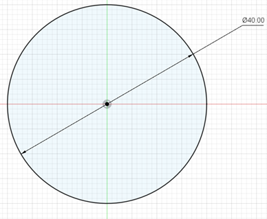
To create the circular plate, create a sketch of a circle of diameter 40 millimeters (mm) on the front plane. (See Figure \(\PageIndex{4}\).)
Step 2 - Extrude circular plate
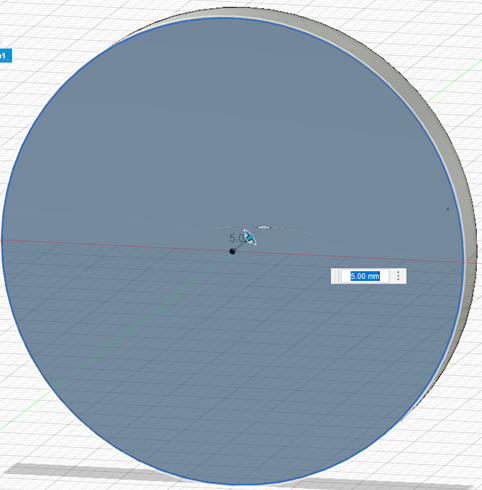
Extrude the circular plate. The extrude length is 5 mm. (See Figure \(\PageIndex{5}\).)
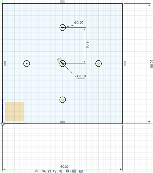
Step 3 - Sketch 5 circles
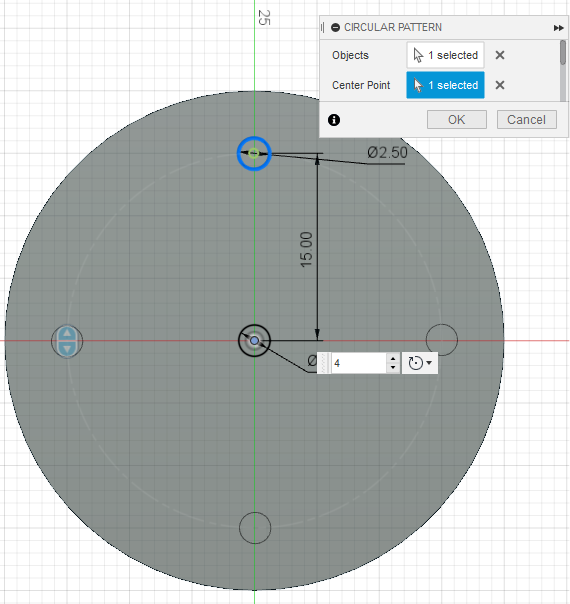
Sketch five different circles of diameter 2.5 mm on the face of the circular plate. Sketch the first circle at the center of the circular plate. Then use the pattern command to create four circles at a distance of 15 mm away from the center circle. Then use the circular pattern command to create four circles. The objects selected are the last circle just created. The center point is the center of the circular plate. (See Figure \(\PageIndex{6}\).)
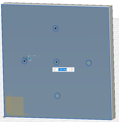
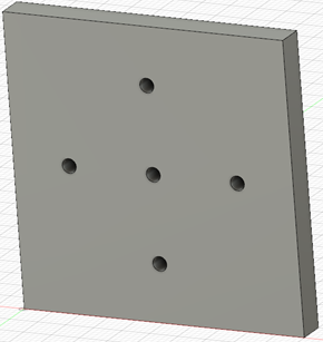
Step 4 - Extrude cut holes
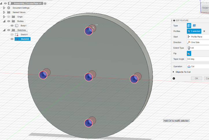
Use extrude-cut to create five holes using the circles sketched in the previous step. (See Figure \(\PageIndex{7}\).)
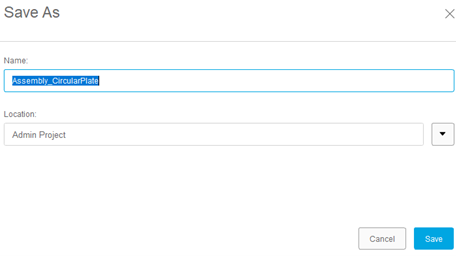
Step 5 - Save circular plate
Save the plate created in the previous step. (See Figure \(\PageIndex{8}\).)
Create the Base Square Plate
Step 1 - Sketch square base plate
Create a sketch for a base square plate. It is a square with sides of 50 mm each. You can also create a sketch of the five circles that will eventually become holes in the plate. The holes’ dimensions and positions are shown in the figure \(\PageIndex{9}\) below and are similar to the ones created on the circular plate, using the pattern command to create four circles at a distance of 15 mm away from the center circle. They are separated equally at an angle of 90°. (See Figure \(\PageIndex{9}\).)
Step 2 - Extrude square
Extrude the square created in the previous step. The extrude length is 5 mm. (See Figure \(\PageIndex{10}\).)
Step 3 - Extrude cut holes
Use Extrude Cut to create holes using the sketches of a circle created in the previous steps. (See Figure \(\PageIndex{11}\).)
Step 4 - Save file
Save the base plate created in the previous steps. (See Figure \(\PageIndex{12}\).)
Create Pin
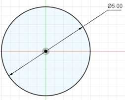
Step 1 - Sketch a circle
Sketch a circle of diameter 5 mm on the front plane. (See Figure \(\PageIndex{13}\).)
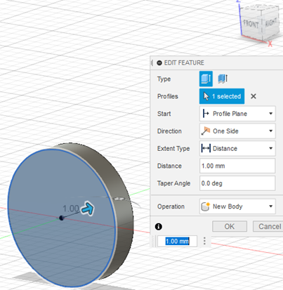
Step 2 - Extrude circle
Extrude the circle created in the previous step. The extrude length is 1 mm. (See Figure \(\PageIndex{14}\).)
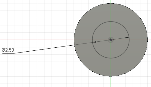
Step 3 - Sketch concentric circle
Sketch a concentric circle of diameter 2.5 mm on the face of the circular disc created in the previous step. (See Figure \(\PageIndex{15}\).)
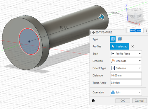
Step 4 - Extrude circle
Extrude the circle created in the previous step. The extrude length is 10 mm. (See Figure \(\PageIndex{16}\).)
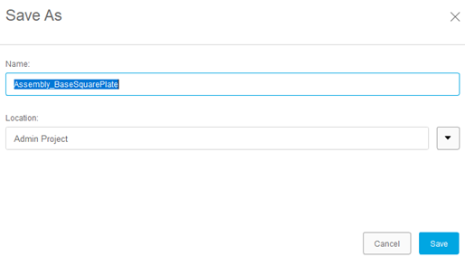
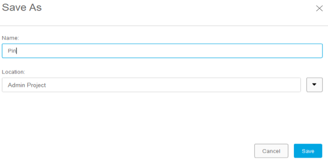
Step 5 - Save file
Save the completed Pin created in the previous steps. (See Figure \(\PageIndex{17}\).)
Create the Final Assembly
In order to create the final assembly of all the components created in the previous steps, they have to be imported into an assembly file and then all the joint constraints need to be applied.
Step 1 - Create and save new design
Create a New Design. Save this New Design.
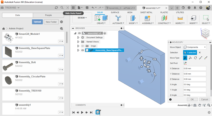
Step 2 - Insert base plate into assembly
Click on the Hide Data Panel to reveal the saved components saved in the account’s cloud library. Right click on the Base Plate and select “Insert into Current Design”. The Screen should look like the following, Figure \(\PageIndex{18}\). Then, select “OK” from the Move/Copy dialogue box. The base plate should tun into a gray color. This implies the position of the component is now fixed.
Step 3 - Import Circular plate
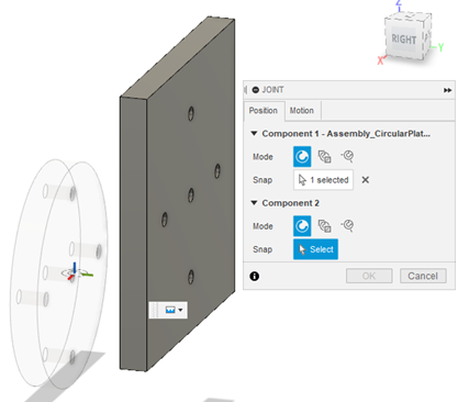
Similarly, import the circular plate into the design. Then select the Joint option from the Assemble drop down menu. Select the origin of the center hole on the bottom of the circular plate as shown in Figure \(\PageIndex{19}\).
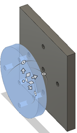
Step 4 - Create joint
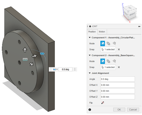
Next, select the origin on the center hole on the front face of the base plate. The circular plate will sit flush on the base plate as shown in Figure \(\PageIndex{20}\). All the holes on the plates will also be aligned after this step is executed correctly.
Step 5 - Import pin
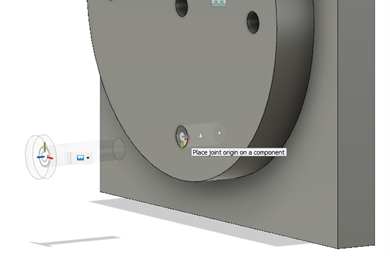
Import a Pin into the current assembly. Then select Joint from the Assembly drop down menu. Select the center of the bottom of the flat head and then select the hole you want to place the rivet in. The Figure \(\PageIndex{21}\) below shows this step.
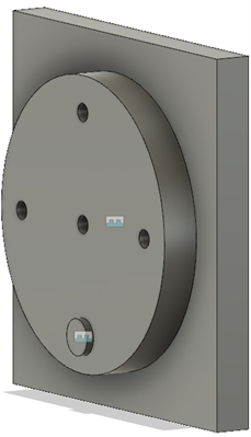
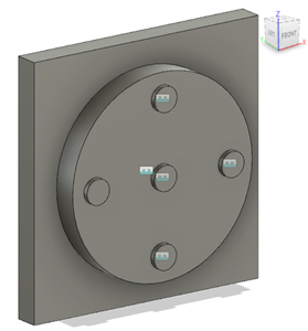
Step 6 - Set remaining pins
Repeat Step 5 four times to set pins in the remaining four (4) holes. Save the completed assembly. (See Figure \(\PageIndex{22}\).)