10.2: Systems Development Life Cycle (SDLC) Model
- Page ID
- 9809
\( \newcommand{\vecs}[1]{\overset { \scriptstyle \rightharpoonup} {\mathbf{#1}} } \)
\( \newcommand{\vecd}[1]{\overset{-\!-\!\rightharpoonup}{\vphantom{a}\smash {#1}}} \)
\( \newcommand{\id}{\mathrm{id}}\) \( \newcommand{\Span}{\mathrm{span}}\)
( \newcommand{\kernel}{\mathrm{null}\,}\) \( \newcommand{\range}{\mathrm{range}\,}\)
\( \newcommand{\RealPart}{\mathrm{Re}}\) \( \newcommand{\ImaginaryPart}{\mathrm{Im}}\)
\( \newcommand{\Argument}{\mathrm{Arg}}\) \( \newcommand{\norm}[1]{\| #1 \|}\)
\( \newcommand{\inner}[2]{\langle #1, #2 \rangle}\)
\( \newcommand{\Span}{\mathrm{span}}\)
\( \newcommand{\id}{\mathrm{id}}\)
\( \newcommand{\Span}{\mathrm{span}}\)
\( \newcommand{\kernel}{\mathrm{null}\,}\)
\( \newcommand{\range}{\mathrm{range}\,}\)
\( \newcommand{\RealPart}{\mathrm{Re}}\)
\( \newcommand{\ImaginaryPart}{\mathrm{Im}}\)
\( \newcommand{\Argument}{\mathrm{Arg}}\)
\( \newcommand{\norm}[1]{\| #1 \|}\)
\( \newcommand{\inner}[2]{\langle #1, #2 \rangle}\)
\( \newcommand{\Span}{\mathrm{span}}\) \( \newcommand{\AA}{\unicode[.8,0]{x212B}}\)
\( \newcommand{\vectorA}[1]{\vec{#1}} % arrow\)
\( \newcommand{\vectorAt}[1]{\vec{\text{#1}}} % arrow\)
\( \newcommand{\vectorB}[1]{\overset { \scriptstyle \rightharpoonup} {\mathbf{#1}} } \)
\( \newcommand{\vectorC}[1]{\textbf{#1}} \)
\( \newcommand{\vectorD}[1]{\overrightarrow{#1}} \)
\( \newcommand{\vectorDt}[1]{\overrightarrow{\text{#1}}} \)
\( \newcommand{\vectE}[1]{\overset{-\!-\!\rightharpoonup}{\vphantom{a}\smash{\mathbf {#1}}}} \)
\( \newcommand{\vecs}[1]{\overset { \scriptstyle \rightharpoonup} {\mathbf{#1}} } \)
\( \newcommand{\vecd}[1]{\overset{-\!-\!\rightharpoonup}{\vphantom{a}\smash {#1}}} \)
\(\newcommand{\avec}{\mathbf a}\) \(\newcommand{\bvec}{\mathbf b}\) \(\newcommand{\cvec}{\mathbf c}\) \(\newcommand{\dvec}{\mathbf d}\) \(\newcommand{\dtil}{\widetilde{\mathbf d}}\) \(\newcommand{\evec}{\mathbf e}\) \(\newcommand{\fvec}{\mathbf f}\) \(\newcommand{\nvec}{\mathbf n}\) \(\newcommand{\pvec}{\mathbf p}\) \(\newcommand{\qvec}{\mathbf q}\) \(\newcommand{\svec}{\mathbf s}\) \(\newcommand{\tvec}{\mathbf t}\) \(\newcommand{\uvec}{\mathbf u}\) \(\newcommand{\vvec}{\mathbf v}\) \(\newcommand{\wvec}{\mathbf w}\) \(\newcommand{\xvec}{\mathbf x}\) \(\newcommand{\yvec}{\mathbf y}\) \(\newcommand{\zvec}{\mathbf z}\) \(\newcommand{\rvec}{\mathbf r}\) \(\newcommand{\mvec}{\mathbf m}\) \(\newcommand{\zerovec}{\mathbf 0}\) \(\newcommand{\onevec}{\mathbf 1}\) \(\newcommand{\real}{\mathbb R}\) \(\newcommand{\twovec}[2]{\left[\begin{array}{r}#1 \\ #2 \end{array}\right]}\) \(\newcommand{\ctwovec}[2]{\left[\begin{array}{c}#1 \\ #2 \end{array}\right]}\) \(\newcommand{\threevec}[3]{\left[\begin{array}{r}#1 \\ #2 \\ #3 \end{array}\right]}\) \(\newcommand{\cthreevec}[3]{\left[\begin{array}{c}#1 \\ #2 \\ #3 \end{array}\right]}\) \(\newcommand{\fourvec}[4]{\left[\begin{array}{r}#1 \\ #2 \\ #3 \\ #4 \end{array}\right]}\) \(\newcommand{\cfourvec}[4]{\left[\begin{array}{c}#1 \\ #2 \\ #3 \\ #4 \end{array}\right]}\) \(\newcommand{\fivevec}[5]{\left[\begin{array}{r}#1 \\ #2 \\ #3 \\ #4 \\ #5 \\ \end{array}\right]}\) \(\newcommand{\cfivevec}[5]{\left[\begin{array}{c}#1 \\ #2 \\ #3 \\ #4 \\ #5 \\ \end{array}\right]}\) \(\newcommand{\mattwo}[4]{\left[\begin{array}{rr}#1 \amp #2 \\ #3 \amp #4 \\ \end{array}\right]}\) \(\newcommand{\laspan}[1]{\text{Span}\{#1\}}\) \(\newcommand{\bcal}{\cal B}\) \(\newcommand{\ccal}{\cal C}\) \(\newcommand{\scal}{\cal S}\) \(\newcommand{\wcal}{\cal W}\) \(\newcommand{\ecal}{\cal E}\) \(\newcommand{\coords}[2]{\left\{#1\right\}_{#2}}\) \(\newcommand{\gray}[1]{\color{gray}{#1}}\) \(\newcommand{\lgray}[1]{\color{lightgray}{#1}}\) \(\newcommand{\rank}{\operatorname{rank}}\) \(\newcommand{\row}{\text{Row}}\) \(\newcommand{\col}{\text{Col}}\) \(\renewcommand{\row}{\text{Row}}\) \(\newcommand{\nul}{\text{Nul}}\) \(\newcommand{\var}{\text{Var}}\) \(\newcommand{\corr}{\text{corr}}\) \(\newcommand{\len}[1]{\left|#1\right|}\) \(\newcommand{\bbar}{\overline{\bvec}}\) \(\newcommand{\bhat}{\widehat{\bvec}}\) \(\newcommand{\bperp}{\bvec^\perp}\) \(\newcommand{\xhat}{\widehat{\xvec}}\) \(\newcommand{\vhat}{\widehat{\vvec}}\) \(\newcommand{\uhat}{\widehat{\uvec}}\) \(\newcommand{\what}{\widehat{\wvec}}\) \(\newcommand{\Sighat}{\widehat{\Sigma}}\) \(\newcommand{\lt}{<}\) \(\newcommand{\gt}{>}\) \(\newcommand{\amp}{&}\) \(\definecolor{fillinmathshade}{gray}{0.9}\)Systems Development Life Cycle (SDLC) Model
SDLC was first developed in the 1960s to manage the large projects associated with corporate systems running on mainframes. It is a very structured process designed to manage large projects with many people's efforts, including technical, business, support professionals. These projects are often costly to build, and they have a large impact on the organization. A failed project or an incorrect business decision to pick a wrong project to fund can be a business or financial catastrophe for an organization.
SDLC is a model defining a process of a set of phases for planning, analysis, design, implementation, maintenance. Chapter 1 discusses that an information system (IS) includes hardware, software, database, networking, process, and people. SDLC has been used often to manage an IS project that may include one, some, or all of the elements of an IS. Let’s walk through each of the five phases of an SDLC as depicted in Figure 10.1:
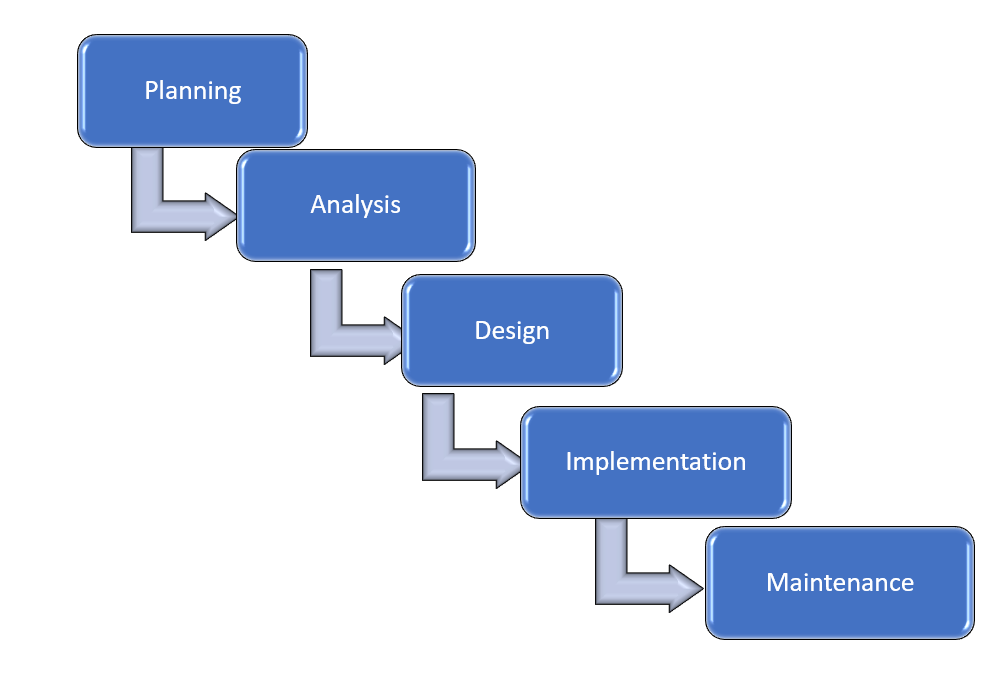
- Planning. In this phase, a request is initiated by someone who acts as a sponsor for this idea. A small team is assembled to conduct a preliminary assessment of the request's merit and feasibility. The objectives of this phase are:
- To determine how the request fits with the company’s strategy or business goals.
- To conduct a feasibility analysis, which includes an analysis of the technical feasibility (is it possible to create this?), the economic feasibility (can we afford to do this?), and the legal feasibility (are we allowed to do this?).
- To recommend a go/no go for the request. If it is a go, then a concept proposal is also produced for management to approve.
- Analysis. Once the concept proposal is approved, the project is formalized with a new project team (including the previous phase). Using the concept proposal as the starting point, the project members work with different stakeholder groups to determine the new system's specific requirements. No programming or development is done in this step. The objectives of this phase are:
- Identify and Interview key stakeholders.
- Document key procedures
- Develop the data requirements
- To produce a system-requirements document as the result of this phase. This has the details to begin the design of the system.
- Design. Once the system requirements are approved, the team may be reconfigured to bring in more members. This phase aims for the project team to take the system requirements document created in the previous phase and develop the specific technical details required for the system. The objectives are:
- Translate the business requirements into specific technical requirement
- Design the user interface, database, data inputs and outputs, and reports
- Produce a system-design document as the result of this phase. . This document will have everything a programmer will need to create the system.
- Implementation. Once a system design is approved, the software code finally gets written in the programming phase, and the development effort for other elements such as hardware also happens. The purpose is to create an initial working system. The objectives are:
- Develop the software code, and other IS components. Using the system- design document as a guide, developers begin to code or develop all the IS project components.
- Test the working system through a series of structured tests such as:
- The first is a unit test, which tests individual parts of the code for errors or bugs.
- Next is a system test, where the system's different components are tested to ensure that they work together properly.
- Finally, the user-acceptance test allows those that will be using the software to test the system to ensure that it meets their standards.
- Iteratively test any fixes again to address any bugs, errors, or problems found during testing.
- Train the users
- Provide documentation
- Perform necessary conversions from any previous system to the new system.
- Produce, as a result, the initial working system that meets the requirements laid out in the analysis phase and the design developed in the design phase.
- Maintenance. This phase takes place once the implementation phase is complete. In this phase, the system must have a structured support process in place to:
- Report bugs
- Deploy bug fixes
- Accept requests for new features
- Evaluate the priorities of reported bugs or requested features to be implemented
- Identify a predictable and regular schedule to release system updates and perform backups.
- Dispose of data and anything else that is no longer needed
Organizations can combine or sub-divide these phases to fit their needs. For example, instead of one phase, Planning, an organization can choose to have two phases: Initiation, Concept; or splitting the implementation into two phases: implementation and testing.
Waterfall Model
One specific SDLC-based model is the Waterfall model, and the name is often thought to be the same as SDLC. It is used to manage software projects as depicted in Fig 10.2 with five phases: Requirements, Design, Implement, Verification, and Maintenance. This model stresses that each phase must be completed before the next one can begin (hence the name waterfall). For example, changes to the requirements are not allowed once the implementation phase has begun, or changes must be sought and approved to a change process. They may require the project to restart from the requirement phase since new requirements need to be approved, which may cause the design to be revised before the implementation phase can begin.
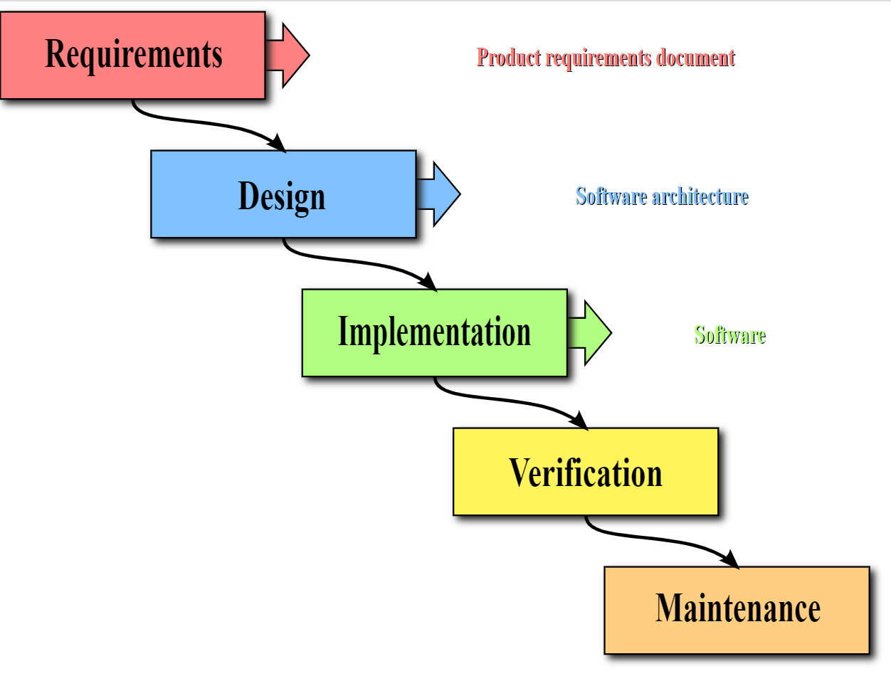
The waterfall model's rigid structure has been criticized for being quite rigid and causing teams to be risk-averse to avoid going back to previous phases. However, there are benefits to such a structure too. Some advantages and disadvantages of SDLC and Waterfall are:
Advantages and Disadvantage of SDLC and Waterfall
|
Advantages |
Disadvantages |
|
The robust process to control and track changes to minimize the number of risks can derail the project unknowingly. |
Take time to record everything, which leads to additional cost and time to the schedule. |
|
Standard and transparent processes help the management of large teams. |
Too much time spent attending meetings, seeking approval, etc. which lead to additional cost and time to the schedule. |
|
Documentation reduces the risks of losing personnel, easier to add people to the project. |
Some members do not like to spend time writing, leading to the additional time needed to complete a project. |
|
Easier to trace a problem in the system to its root whenever errors are found, even after the project is completed. |
It is difficult to incorporate changes or customers’ feedback since the project has to go back to one or more previous phases, leading teams to become risk-averse. |
Other models are developed over time to address these criticisms. We will discuss two other models: Rapid Application Development and Agile, as different approaches to SDLC.
Rapid Application Development (RAD)
Rapid application development (RAD) is a software development (or systems-development) methodology that focuses less on planning and incorporating changes on an ongoing basis. RAD focuses on quickly building a working model of the software or system, getting feedback from users, and updating the working model. After several iterations of development, a final version is developed and implemented. Let’s walk through the four phases in the RAD model as depicted in Fig. 10.3.
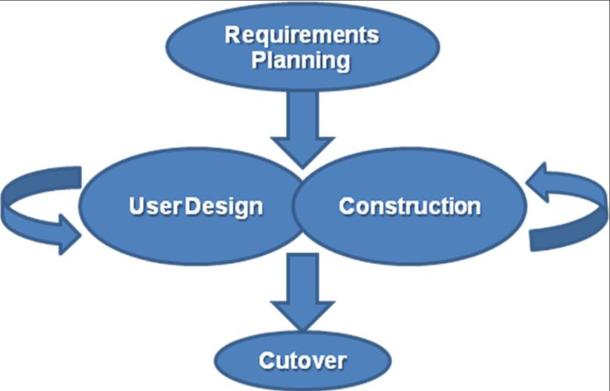
- Requirements Planning. This phase is similar to the planning, analysis, and design phases of the SDLC.
- User Design. In this phase, the users' representatives work with the system analysts, designers, and programmers to interactively create the system's design. One technique for working with all of these various stakeholders is the Joint Application Development (JAD) session. A JAD session gets all relevant users who interact with the systems from different perspectives, other key stakeholders, including developers, to have a structured discussion about the system's design. The objectives are for users to understand and adopt the working model and for the developers to understand how the system needs to work from the user’s perspective to provide a positive user experience.
- Construction. In the construction phase, the tasks are similar to SDLC’s implementation phase. The developers continue to work interactively with the users to incorporate their feedback as they interact with the working model that is being developed. This is an interactive process, and changes can be made as developers are working on the program. This step is executed parallel with the User Design step in an iterative fashion until an acceptable version of the product is developed.
- Cutover. This step is similar to some of the SDLC implementation phase tasks. The system goes live or is fully deployed. All steps required to move from the previous state to using the new system are completed here.
Compared to the SDLC or Waterfall model, the RAD methodology is much more compressed. Many of the SDLC steps are combined, and the focus is on user participation and iteration. This methodology is better suited for smaller projects and has the added advantage of giving users the ability to provide feedback throughout the process. SDLC requires more documentation and attention to detail and is well suited to large, resource-intensive projects. RAD is better suited for projects that are less resource-intensive and need to be developed quickly. Here are some of the advantages and disadvantages of RAD:
Advantages and Disadvantage of RAD
|
Advantages |
Disadvantages |
|
Increase quality due to the frequency of interacting with the users |
Risks of weak implementation of features that are not visible to the users, such as security |
|
Reduce risks of users’ refusal to accept the finished product |
Lack of control over the system changes due to a working version's fast turn-around to address users’ issues. |
|
Improve chances of on-time, on-budget completion as users update in real-time, avoiding surprises during development. |
Lack of design since changes are being put in the system might unknowingly affect other parts of the system. |
|
Increase interaction time between developers/experts and users |
Scarce resources as developers are tied up, which could slow down other projects. |
|
Best suited for small to medium size project teams |
Difficult to scale up to large teams |
Agile Development Methodologies
Agile methodologies are a group of methodologies that utilize incremental changes focusing on quality and attention to detail. Each increment is released in a specified period of time (called a time box), creating a regular release schedule with particular objectives. While considered a separate methodology from RAD, they share some of the same principles: iterative development, user interaction, and changeability. The agile methodologies are based on the “Agile Manifesto,” first released in 2001.
The characteristics of agile methods include:
- small cross-functional teams that include development-team members and users;
- daily status meetings to discuss the current state of the project;
- short time-frame increments (from days to one or two weeks) for each change to be completed; and
- At the end of each iteration, a working project is completed to demonstrate to the stakeholders.
In essence, the Agile approach puts a higher value on tasks that promote interaction, build frequent working versions, customers/user collaboration, and quick response to change and less emphasis on processes and documentation. The agile methodologies' goal is to provide an iterative approach's flexibility while ensuring a quality product.
There are a variety of models that are built using Agile methodologies. One such example is the Scrum development model.
Scrum development model
This model is suited for small teams who work to produce a set of features within fixed-time interactions, such as two- to four weeks, called sprints. Let’s walk through the four key elements of a Scrum model as depicted in Fig 10.4.
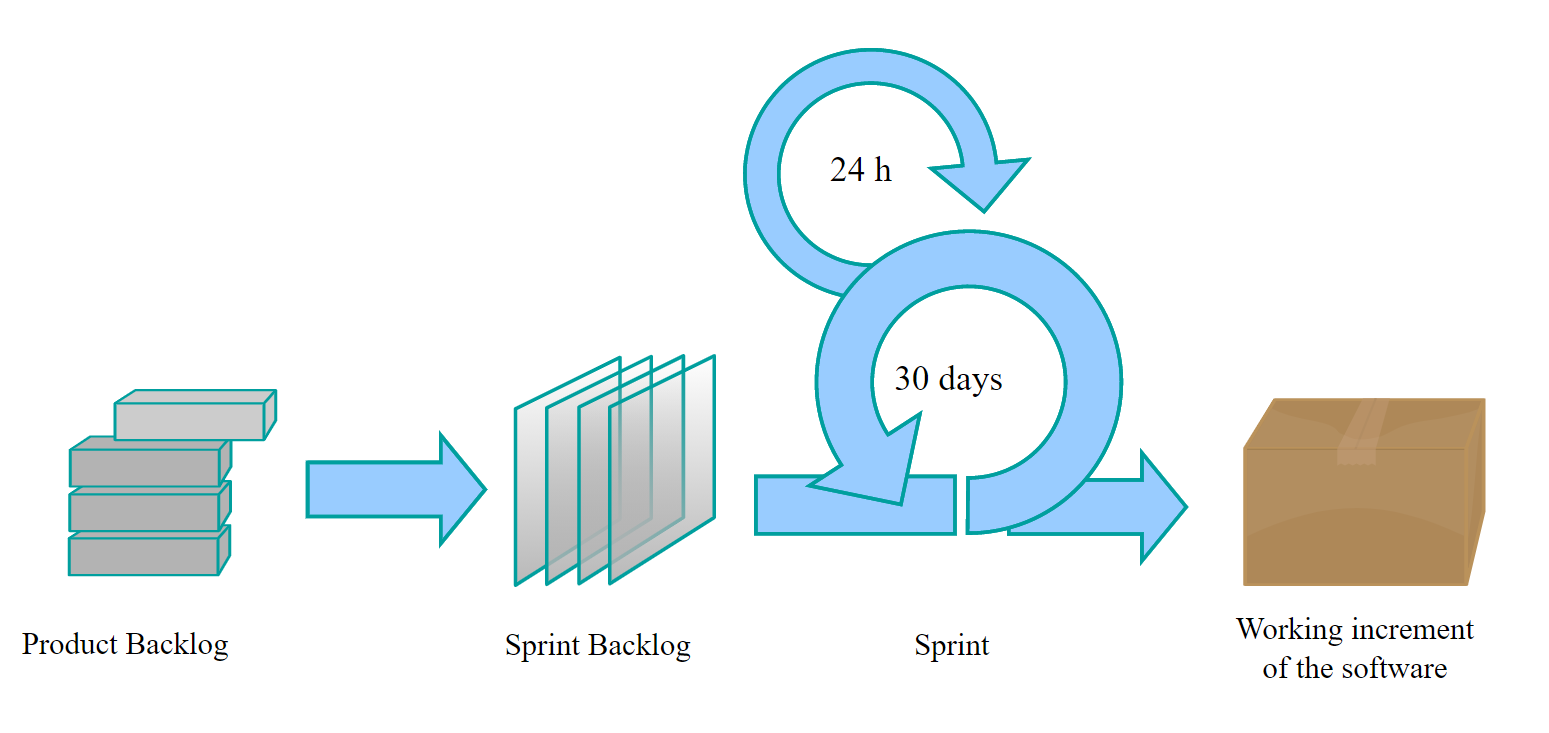
Fig 10.4. The Scrum project management method. Image by Lakeworks is licensed CC BY-SA 4.0
- Product backlog. This is a detailed breakdown list of work to be done. All the work is prioritized based on criteria such as risks, dependencies, mission-critical, etc. Developers select their own tasks and self-organize to get the work done.
- Sprint backlog. This is a list of the work to be done in the next sprint.
- Sprint. This is a fixed time, such as 1-day, 2-weeks, or 4-weeks, as agreed by the team. A daily progress meeting is called a daily scrum, typically a short 10-15 minute meeting facilitated by a scrum master whose role is to remove roadblocks for the team.
- Working increment of the software. This is a working version that is incrementally built with the breakdown lists at the end of the sprints.
Lean Methodology
One last methodology we will discuss is a relatively new concept taken from the business bestseller The Lean Startup, by Eric Reis.
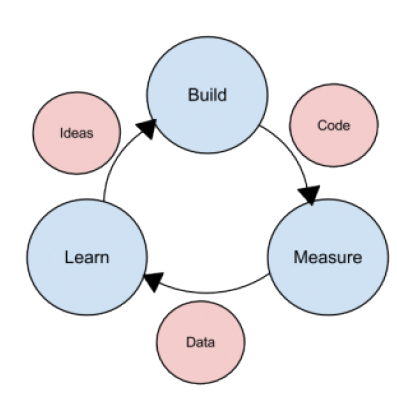
This methodology focuses on taking an initial idea and developing a minimum viable product (MVP). The MVP is a working software application with just enough functionality to demonstrate the idea behind the project. Once the MVP is developed, it is given to potential users for review. Feedback on the MVP is generated in two forms: (1) direct observation and discussion with the users, and (2) usage statistics gathered from the software itself. Using these two forms of feedback, the team determines whether they should continue in the same direction or rethink the project's core idea, change the functions, or create a new MVP. This change in strategy is called a pivot. Several iterations of the MVP are developed, with new functions added each time based on the feedback, until a final product is completed.
The biggest difference between the lean methodology and the other methodologies is that the system's full set of requirements is unknown when the project is launched. As each iteration of the project is released, the statistics and feedback gathered are used to determine the requirements. The lean methodology works best in an entrepreneurial environment where a company is interested in determining if their idea for a software application is worth developing.
References:
Manifesto for Agile Software Development (2001). Retrieved December 10, 2020, from http://agilemanifesto.org/
The Lean Startup. Retrieved on December 9, 2020, from http://theleanstartup.com/


